Design of an Adaptive Lock-in Amplifier for the Terahertz System
International Journal of Industrial and Operations Research
(ISSN: 2633-8947)
Volume 4, Issue 1
Research Article
DOI: 10.35840/2633-8947/6509

Article Formats
Design of an Adaptive Lock-in Amplifier for the Terahertz System
Table of Content
Figures
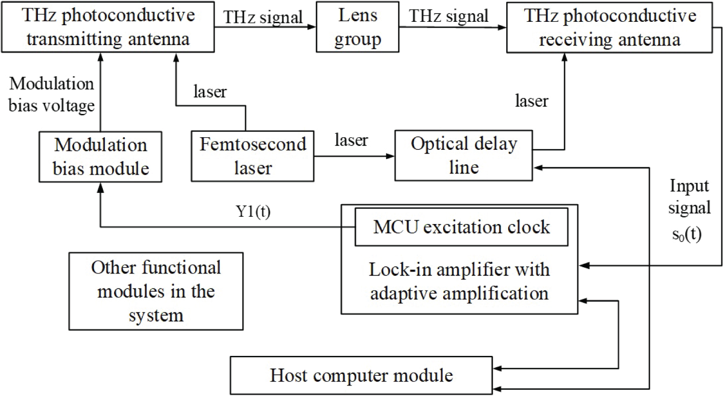
Figure 1: Schematic of terahertz time domain....
Schematic of terahertz time domain spectroscopy system.
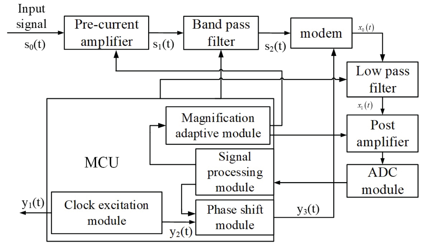
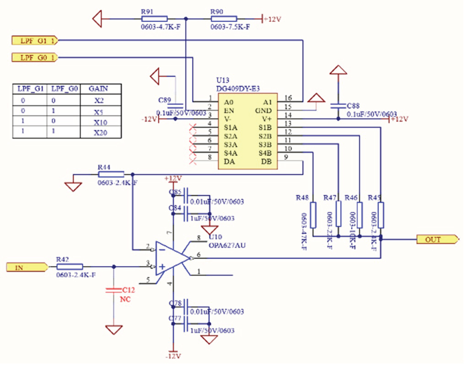
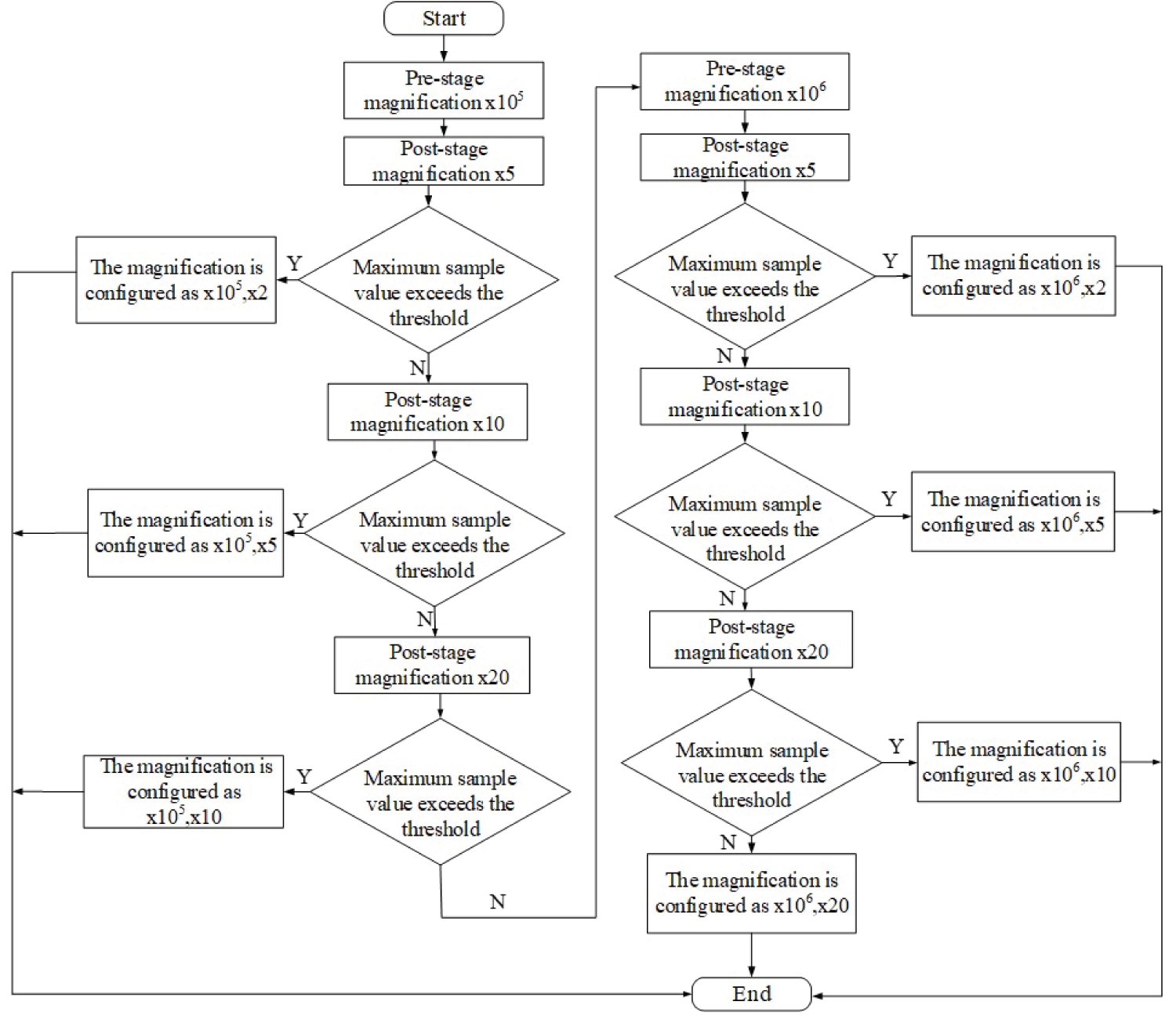
Figure 4: Flow chart of adaptive configuration.....
Flow chart of adaptive configuration of magnification.
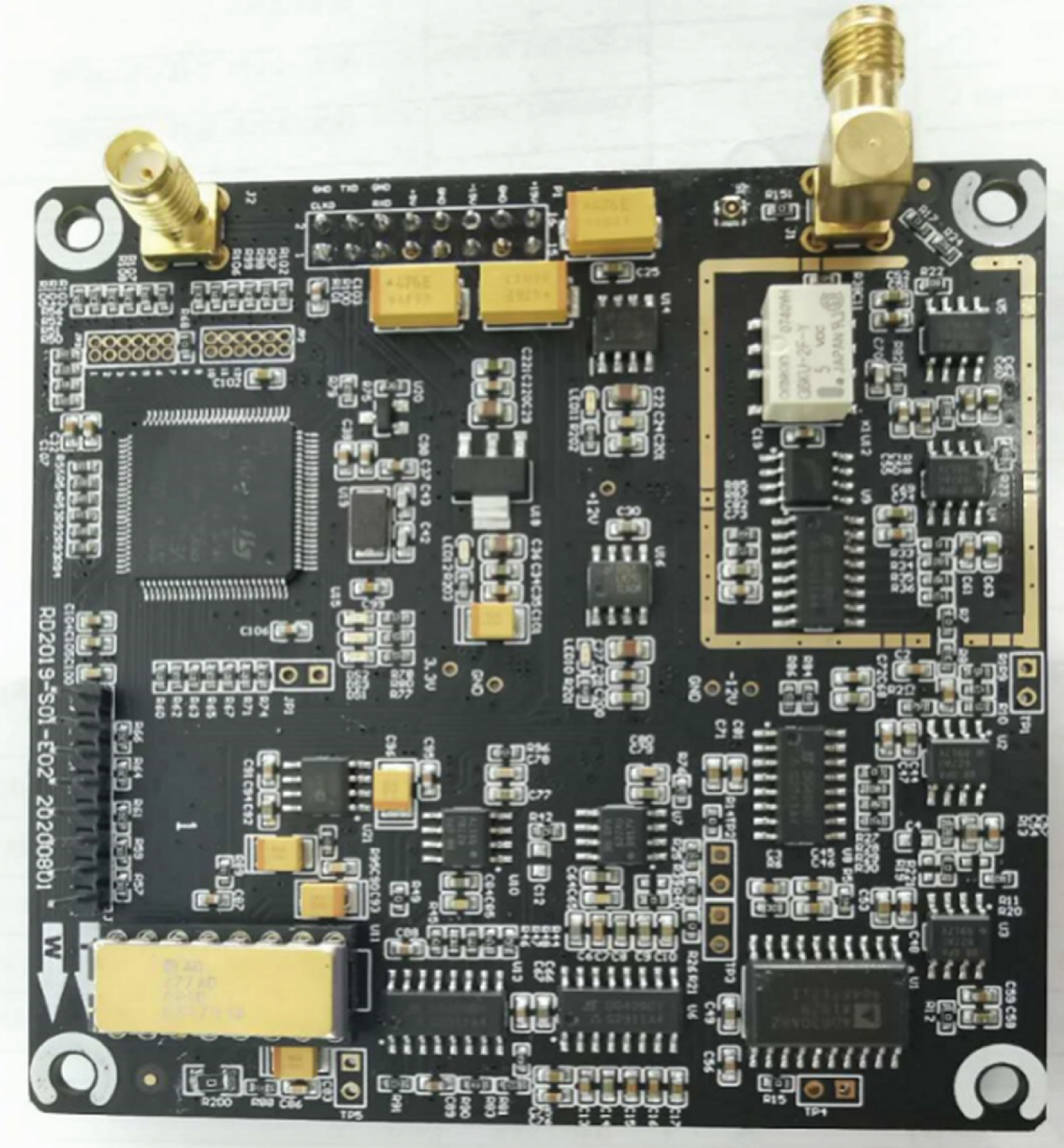
Figure 5: The picture of the lock-in amplifier....
The picture of the lock-in amplifier produced and processed.
References
- Zhao K, Zhan H (2018) Terahertz spectrum analysis technology. Science Press, Beijing.
- Brundermann E, Hubers H-W, Kimmitt MFG (2016) Terahertz techniques. National Defense Industry Press, Beijing, China.
- Wang W (2019) Study on terahertz technology for paper thickness measurement. Beijing, China.
- Xing L (2016) Nondestructive testing of aviation foam core materials and sandwich structures using terahertz time domain spectroscopic imaging technology. Changchun, China.
- Tu W (2017) Terahertz wave propagation in marine protective coatings and nondestructive testing signal analysis. Fuzhou, China.
- Zhang Y (2019) Research on microwave reflectivity In-situ test technology of stealth coating. Chengdu, China.
- Xu Z (2018) Research on terahertz nondestructive testing of rubber material. Changchun, China.
- Xiong X, Zhang H, Han J, et al. (2017) Design of lock-in amplifier in terahertz test system. Electrical Measurement and Instrumentation 54: 89-93.
- Qu Y (2016) Lock-in amplifier in terahertz time domain spectrometer. Information recording materials 17: 175-178.
- Liu Y (2015) The design of fast THz-TDS optical delay line and the research on digital locked-in amplifier technology. Tianjin, China.
- Xia Z (2015) Study CD552R3-III analog lock-in amplifier and rapid acquisition system for terahertz pulse signal. Tianjin, China.
- Lomg N (2014) Research on THz-TDS lock-in amplifier technology. Tianjin, China.
- Huang Z, Long N, He M, Hu Z, Liu Y (2015) Programmable lock-in amplifier technology for THz-TDS. Optoelectronic Engineering 42: 7-11.
- Dietz RJB, Vieweg N, Puppe T, Zach A, Globisch B, et al. (2014) All fiber-coupled THz-TDS system with kHz measurement rate based on electronically controlled optical sampling. Opt Lett 39: 6482-6485.
- Gao J (2019) Detection of weak signals. Tsinghua University Press, Beijing, China.
- Sun C (2018) A lock-in amplifier system and methods based on FPGA. Patent 107,707,252, China.
- Pan Q (2019) Fast and practical design of active power filter. People's Posts and Telecommunications Press, Beijing, China.
- Qin X (2020) A lock-in amplifier based on neural network. Patent 110,768,661, China.
Author Details
Zhaohui Zhang1*, Yongli Liu2 and Xinyong Zhu1
1Qingdao Quenda Terahertz Technology Co., Ltd, Qingdao, China
2China Academy of Engineering Physics, Mianyang, China
Corresponding author
Zhaohui Zhang, Qingdao Quenda Terahertz Technology Co., Ltd, Qingdao, 266000, China.
Accepted: February 06, 2021 | Published Online: February 08, 2021
Citation: Zhang Z, Liu Y, Zhu X (2021) Design of an Adaptive Lock-in Amplifier for the Terahertz System. Int J Ind Operations Res 4:009.
Copyright: © 2021 Zhang Z, et al. This is an open-access article distributed under the terms of the Creative Commons Attribution License, which permits unrestricted use, distribution, and reproduction in any medium, provided the original author and source are credited.
Abstract
In order to extract the weak terahertz signal in the terahertz time-domain spectroscopy (THz-TDS), and to solve the problem of single amplification of the existing lock-in amplifier or manual adjustment of the amplification, a lock-in amplifier with self-adaptive adjustment function for phase and amplification is designed. Compared with the traditional lock-in amplifier, it reduces the use of electronic components such as phase shifters, modulators and summators, and reduces the development cost of the circuit. The phase shifting module and the amplification factor of the amplifying circuit are controlled by the MCU control unit and the magnitude of the received feedback signal respectively. The dynamic range of the terahertz time-domain spectroscopy system using phase and amplification adaptive lock-in amplifiers indoors can reach 70 dB. The test results show that the designed lock-in amplifier can effectively improve the dynamic range of the terahertz system,and is more convenient for real-life applications.
Keywords
Lock-in amplifier, The terahertz time-domain spectroscopy system, Weak signal, Signal to noise ratio
Introduction
Terahertz wave [1,2] refers to electromagnetic waves with a frequency of 0.1 THz ~ 10 THz (1 THz = 1012 Hz), located between the microwave and infrared. With the advantages such as strong penetrability, low photon energy, and fingerprint spectrum, terahertz wave has important application prospects in the fields of substance identification, safety inspection, non-destructive inspection of materials and structures, biopsy of biological tissues, and wireless communication [3-7]. At present, the more mature terahertz spectroscopy technology is based on the generation and the detection of the ultrafast photoelectronic terahertz wave. If you can realize the intuitive measurement of terahertz pulses, it is necessary to measure the current formed by photo-generated carriers generated by the THz photoconductive receiving antenna, and the current formed by photo-generated carriers is at the uA level [8]. Traditional weak signal detection methods usually include coherent detection, sampling average and digital filtering, probability density function measurement, narrowband filtering, etc. In addition, there are also some new weak signal detection theories and methods, such as adaptive filtering [9]. Lock-in amplifier is based on the theory of maximum-likelihood estimation. It is a detection instrument that uses correlation detection as a means to detect and extract weak signals. Therefore, the lock-in amplifier module has become the first choice for photo-generated carrier measurement tools.
Due to the rapid development of THz technology and actual use requirements, some research institutions have cooperated with some famous instrument manufacturers to develop miniaturized and easy-to-use THz instruments [10-12], and some laboratories produce practical THz instruments themselves. Some high-tech companies that originally produced optoelectronic products have also started the development of THz instruments with their own technological advantages. Some bottlenecks have been encountered in the development of terahertz time-domain spectroscopy systems. Although ordinary commercial lock-in amplifiers have better amplification effects, they are bulky and expensive, which is not applicable to the commercialization of THz equipment.
In the terahertz time-domain spectroscopy system, in order to solve the problem of the existing lock-in amplifier with single magnification or manual adjustment of the magnification, and to reduce the difficulty of using the lock-in amplifier. In this paper, a lock-in amplifier with adaptive adjustment of phase and amplification is designed. The phase shift module is controlled by its own MCU control unit and the magnitude of the received feedback signal to adjust the phase and match the amplification of the amplifier circuit. The designed lock-in amplifier is applied to the terahertz time-domain spectroscopy system for testing and verification. The experimental results confirm that this self-adaptive, miniaturized, and integrated lock-in amplifier has practical value.
System Composition and Working Principle
Basic composition of terahertz time-domain spectroscopy system
The terahertz time domain spectroscopy system [13,14] is mainly composed of femtosecond lasers, modulated bias modules, phase and amplification adaptive lock-in amplifiers, optical delay lines, THz photoconductive transmitting and receiving antennas, lens groups, and PC terminals. The upper computer module and other functional modules are composed, as shown in Figure 1.
The laser pulse with femtosecond pulse width from the ultrafast femtosecond laser is divided into two paths. One path is used as the pump light to excite the THz photoconductive transmitting antenna to generate photogenerated free carriers. These photogenerated free carriers are biased at a frequency of 10 KHz. Under the action of the electric field, it moves to form an instantaneous current and radiates THz pulses. The other is used as a detection pulse and a terahertz pulse to irradiate the electrode gap of the THz photoconductive receiving antenna at the same time. The detection pulse generates instantaneously photogenerated free carriers in this area and forms a current under the drive of the terahertz electric field, which is obtained by detecting the current size.
The PC terminal host computer module realizes the detection pulse by controlling the optical delay line to sample and measure the electric field intensity of the terahertz pulse and can obtain a weak current signal proportional to the electric field intensity of the terahertz pulse, the magnitude is uA level, which is submerged in noise.
The lock-in amplifier can extract the weak signal proportional to the intensity of the THz pulse electric field [15] and record the time-domain waveform of the terahertz pulse through the PC terminal host computer module.
The working principle of lock-in amplifier
The phase and amplification adaptive lock-in amplifier is mainly composed of 7 parts, pre-current amplifier, band-pass filter, modem, low-pass filter, post-amplifier, ADC module and MCU control unit [16]. See Figure 2.
The designed band-pass filter in the lock-in amplifier is a voltage-controlled voltage source band-pass filter with a Q value of 8, and the low-pass filter is a second-order Butterworth filter [17]. The bandwidth of the band-pass filter and the low-pass filter can be manually configured by the MCU control unit. The design method is the same as that of the post-amplifier described below. The programmable DG409 analog switch chip is used to manually configure the bandwidth according to actual needs.
The excitation clock module in the MCU control unit generates rectangular wave with a frequency of 10 KHz and a duty cycle of 50%, drives the modulation bias module to generate a periodic bias signal, and then stimulates the THz photoconductive antenna to generate a periodic THz signal.
The excitation clock module in the MCU control unit generates a square wave signal with a frequency of 10 KHz and a duty cycle of 50%, drives the modulation bias module to generate a periodic bias signal, and then stimulates the THz photoconductive antenna to generate a periodic THz signal. The THz signal is converted into a weak current signal after passing through the THz photoconductive receiving antenna. It is amplified by the pre-current amplifier and then converted into a voltage signal , is filtered by a band-pass filter and then becomes . Among them, and , , are all signals of the same frequency and n (t) is the channel noise, can be expressed as
and are periodic signals with the same frequency and phase with adjustable frequency and duty cycle.
is the signal after the phase is adjusted by the phase shift module.
The modulation and demodulation process is
After is filtered by a low-pass filter, the high-frequency components in the signal are filtered, the signal becomes:
is sampled by the ADC module after passing through the post amplifier and finally uploaded to the MCU unit.
Design and Implementation of Adaptive Lock-in Amplifier
Design and realization of amplifier circuit
The amplifier circuit is composed of a pre-current amplifier and a post-amplifier. The pre-current amplifier is a transimpedance amplifier with two different magnifications. The two magnifications are times and times. Its main function is to amplify the received weak THz current signal and convert the THz current signal into a voltage signal. The post-amplifier is to amplify the power of the signal after passing through the low-pass filter. There are four design magnifications of 2 times, 5 times, 10 times and 20 times.
The pre-current amplifier uses a programmable relay to control the amplification factor, and the subsequent amplifier uses the programmable analog switch chip DG409 for control. Take the later amplifier as an example, the design circuit is shown in Figure 3.
DG409 is a dual 4-channel differential analog switch. The MCU control unit adaptively configures the DG409 chip through internal logic to select the amplification factor of the post-amplifier [18], which solves the problem that the existing lock-in amplifier has a single amplification factor or needs to manually configure the amplification factor and simplifies the use of the lock-in amplifier.
Design and realization of phase adaptive adjustment
The signal processing module in the MCU control unit receives the signal uploaded by the ADC module and stores the received signal in a cycle of a certain length. At the same time, it identifies the maximum value in the stored signal, the latest received signal is compared with the maximum value that has been identified. By periodically comparing the maximum value, it is used to adaptively adjust the phase and then adjust the magnification.
After the signal acquisition of the entire delay range is completed, the MCU control unit can identify the main peak signal. The host computer module controls the optical delay line to reciprocate within the delay range near the main peak. The signal processing module of the MCU control unit controls the phase shift module to adjust the phase by periodically comparing the received data with the maximum value.
According to the phase adjustment command provided by the signal processing module, the phase shift module shifts the phase of the input signal by 1° and outputs every cycle, and are the same frequency signal. When the received maximum value is the maximum value or the received data is equal to the maximum value, the phase of is considered to be the best phase at this time, that is . At this time, the output signal of the low-pass filter is , the lock-in amplifier has completed the adaptive adjustment of the phase.
Compared with the traditional lock-in amplifier design, the design of this paper reduces the 90° phase shift circuit, reduces the use of modulators and summers, and reduces the design and processing cost of the lock-in amplifier.
Design and implementation of adaptive adjustment of magnification
After the lock is adjusted to the best phase, the signal acquisition module in the MCU control unit periodically compares the relationship between the maximum value of the sampled signal and the threshold to adaptively configure the amplification factors of the front and rear amplifier circuits. After the amplification adaptive module starts, configure the amplification factor of the pre-current amplifier as 105 times, and the amplification factor of the post-amplifier to 5 times. After the system completes the acquisition of the main peak of the THz signal, the signal processing module will compare the relationship between the maximum value of the acquired signal and the set signal threshold. When the collected maximum value exceeds the system threshold, the amplification factor adaptive module will configure the amplification factor of the front and rear stage amplifier circuit to be 105 times and 2 times. At this time, the optimal amplification factors of the pre-circuit amplifier and the post-stage amplifier are 105 times and 2 times respectively. If the maximum value collected does not exceed the system threshold, the magnification adaptive module configures the magnification of the front and rear amplifier circuits as 105 times and 10 times. The system re-acquires the main peak of the THz signal, and then continues to compare with the system threshold according to the self-adapting configuration process of the amplification factor, until the optimal combination of amplification factors of the pre-circuit amplifier and the post-stage amplifier circuits is found. Figure 4 shows the flow chart of self-adaptive configuration of magnification.
In this paper, the design of the MCU control unit adaptively configures the magnification scheme of the front and rear amplifier circuits, which effectively solves the problem of single magnification or manual adjustment of the magnification when the lock-in amplifier is working, that can make the terahertz time-domain spectroscopy system get the maximum signal-to-noise ratio in the working process.
PCB and low noise design
The PCB of the lock-in amplifier adopts a single-panel design. In order to reduce the influence of power supply noise on signal acquisition, the working power supply selects an LDO with a small power supply ripple and uses ± 12 V and 3.3 V for power supply. The PCB design adopts the division design of each functional module, and rationally lays out the power supply, analog devices and digital devices, distinguishes the digital ground from the analog ground according to the signal direction and working characteristics, and ensures that the analog power supply and the digital power supply are divided and will not interfere with each other. The final design of the lock-in amplifier has a PCB size of 80 mm × 80 mm, which effectively reduces the size of the lock-in amplifier, making the designed lock-in amplifier very suitable for being embedded in a small-volume terahertz time-domain spectroscopy system. The physical diagram of the designed lock-in amplifier is shown in Figure 5.
Experiment and System Performance Analysis
Construction of the experimental system
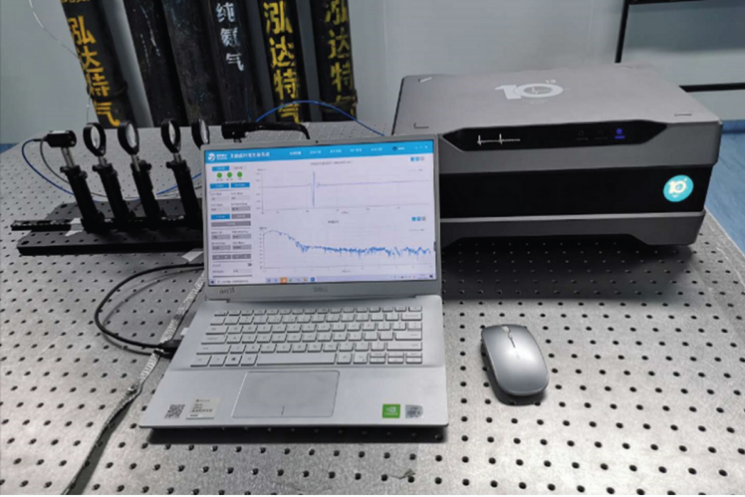
This article uses the high-precision terahertz time-domain spectroscopy system developed by Quenda Terahertz Technology Co., Ltd., the model is QT-TS1000. After setting up the optical system, apply the designed phase and amplification self-adaptive lock-in amplifier to the system. The QT-TS1000 system has a maximum delay range of 560 ps and a spectral resolution of 2 GHz. The constructed terahertz time-domain spectroscopy system is shown in Figure 6.
The frequency of the excitation signal provided by the lock-in amplifier to the modulation bias module is 10 KHz, the integration time of the system is 100ms, the phase of the lock-in amplifier after adaptive adjustment is 36°, and the amplification factor of the pre-current amplifier after adaptive adjustment is 105 times, the magnification of the post-amplifier is 10 times.
Test results and analysis
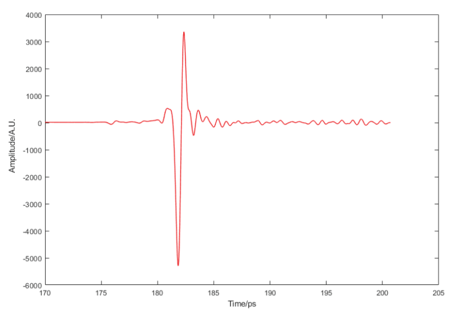
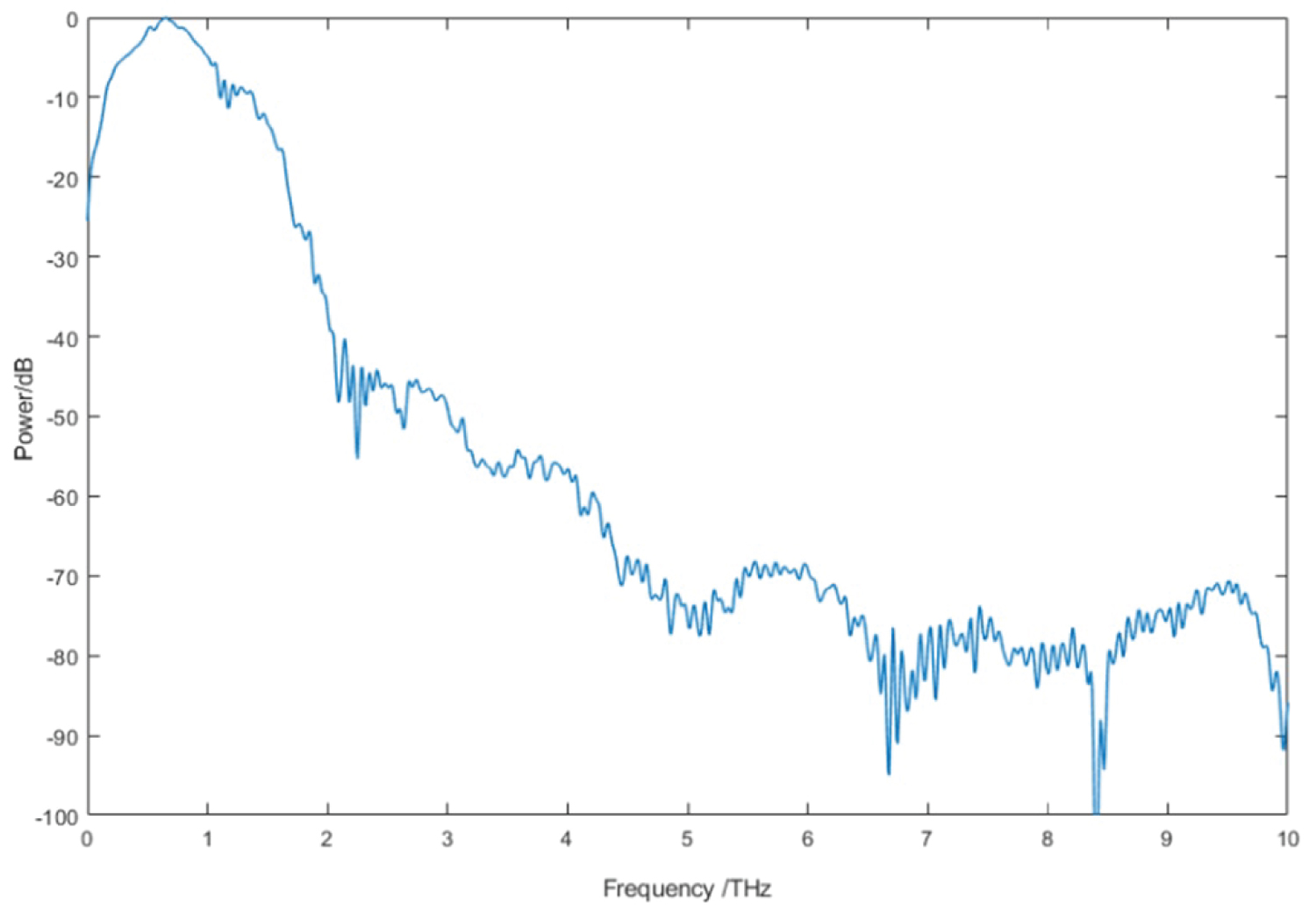
Under laboratory conditions, the temperature is 25 ℃, the air humidity is 40%, and the designed phase and amplification self-adaptive lock-in amplifier is used. The PC terminal host computer module of the QT-TS1000 system configures the system to work with a delay range of 170 ps ~ 200 ps, the step length of the optical delay line is 0.02 ps. The time-domain waveform of the terahertz signal obtained by the test is shown in Figure 7, and the frequency-domain waveform of the terahertz signal is shown in Figure 8.
The time-domain waveform of the terahertz signal is the intensity information of the terahertz signal sampled by the lock-in amplifier, and the frequency-domain waveform is the time-domain signal obtained after Fourier transform without noise reduction. Obvious water vapor absorption peaks can be seen from the spectrum of the terahertz signal in Figure 8. The spectrum width of the system obtained by the test is above 5THz, and the dynamic range of the system can reach 72 dB. The test results shows that the designed phase-and-magnification lock-in amplifier is applied to the detection of weak signals in the terahertz time-domain spectroscopy system, and can recover signals from data with a signal-to-noise ratio of -72 dB.
Conclusion
The lock-in amplifier designed in this paper with adaptive function of phase and amplification can realize the adaptive adjustment of signal demodulation phase and the adaptive configuration of circuit amplification. The lock-in amplifier is applied to the terahertz time-domain spectroscopy system, it is tested under the conditions that the bias modulation frequency is 10 KHz, the temperature is 25 ℃, and the humidity is 40%. The lock-in amplifier can recover signals from data with a signal-to-noise ratio of -72 dB. In the terahertz time-domain spectroscopy system, relying on the lock-in amplifier to increase the dynamic range of the system has approximately reached the bottleneck. If you continue to optimize the lock-in amplifier to increase the dynamic range, it is costly, which is not applicable to the system as a product. However, two methods can be used to improve the dynamic range of the terahertz system by reducing the noise of the signal or adding a coded modulation signal to the modulation signal.
Acknowledgments
This work was supported by the National Natural Science Foundation of China (Grant Nos. 11704358 and 11604316).