
International Journal of Optics and Photonic Engineering
(ISSN: 2631-5092)
Volume 6, Issue 1
Research Article
DOI: 10.35840/2631-5092/4529

Article Formats
Design and Application of Optical System Based on Terahertz Time-of-Flight Imaging
Table of Content
Figures
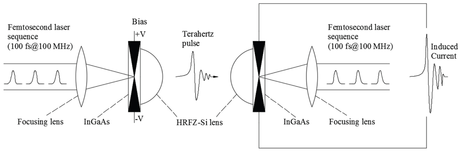
Figure 1: Schematic of Terahertz photoconductive....
Schematic of Terahertz photoconductive antenna launch and detection.
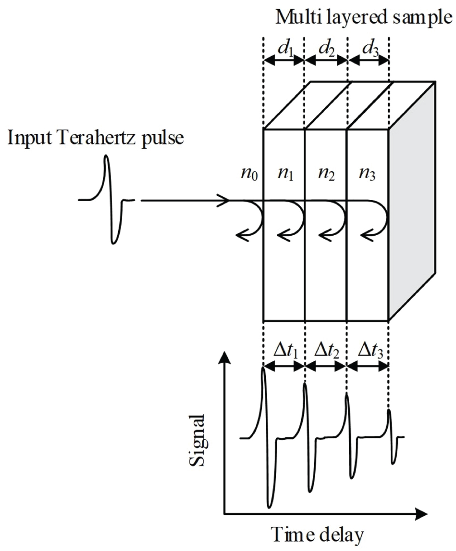
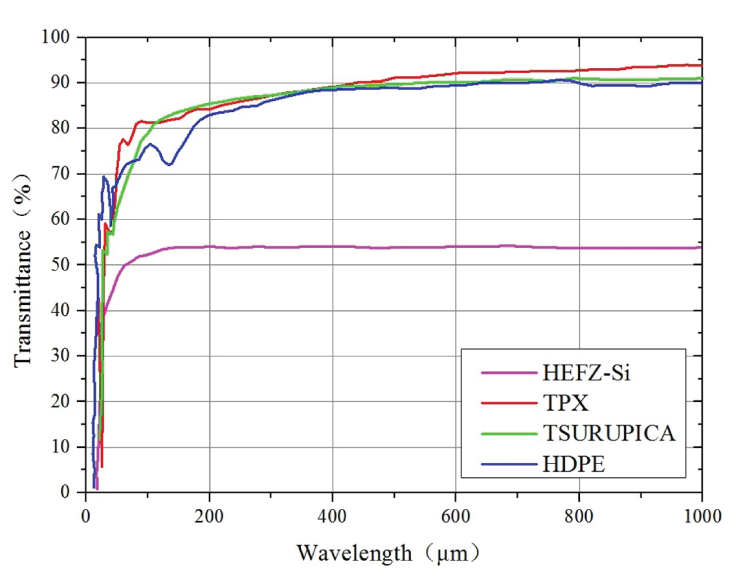
Figure 3: Transmittance curve of 2 mm-thick....
Transmittance curve of 2 mm-thick different materials in the Terahertz band.
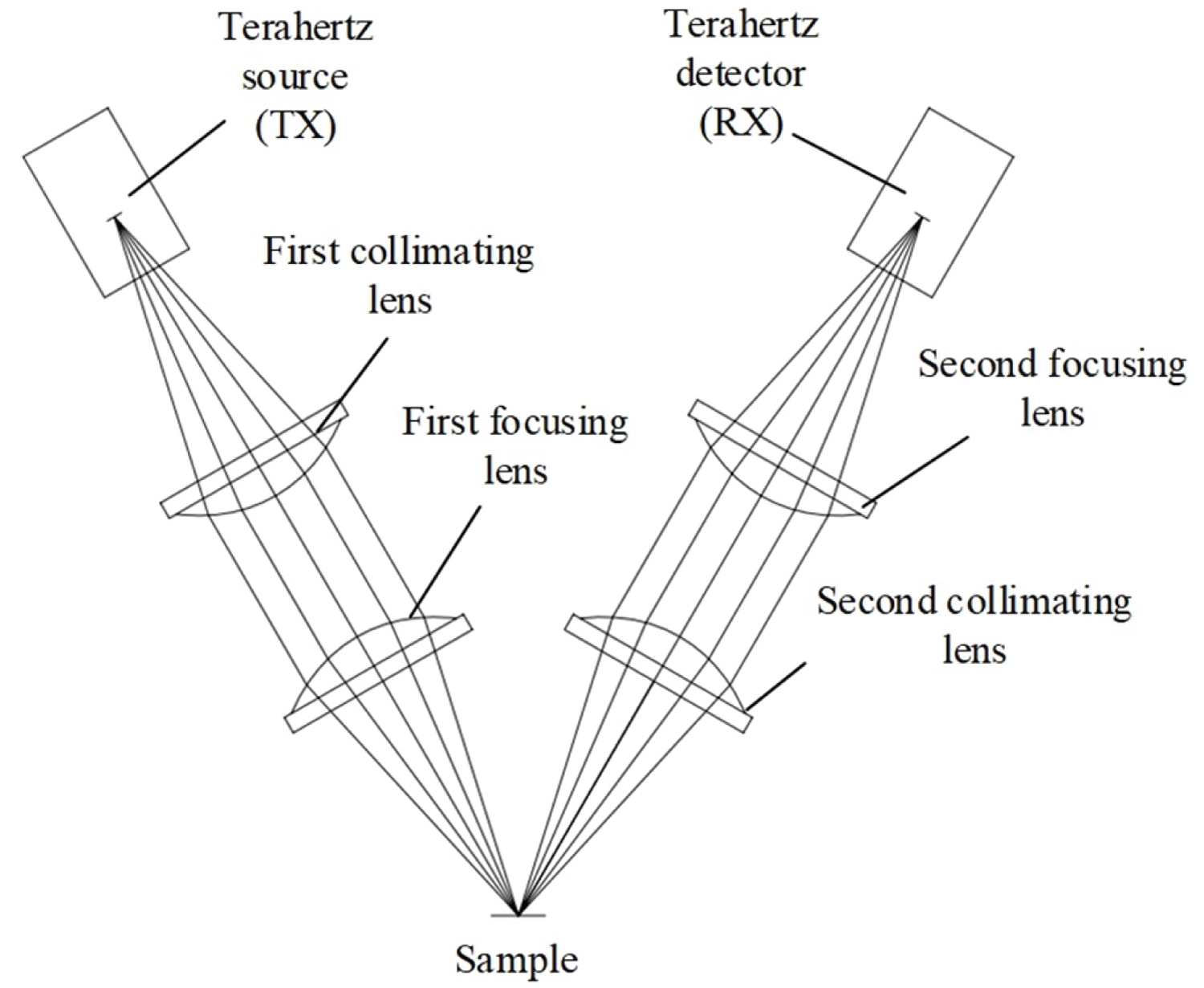
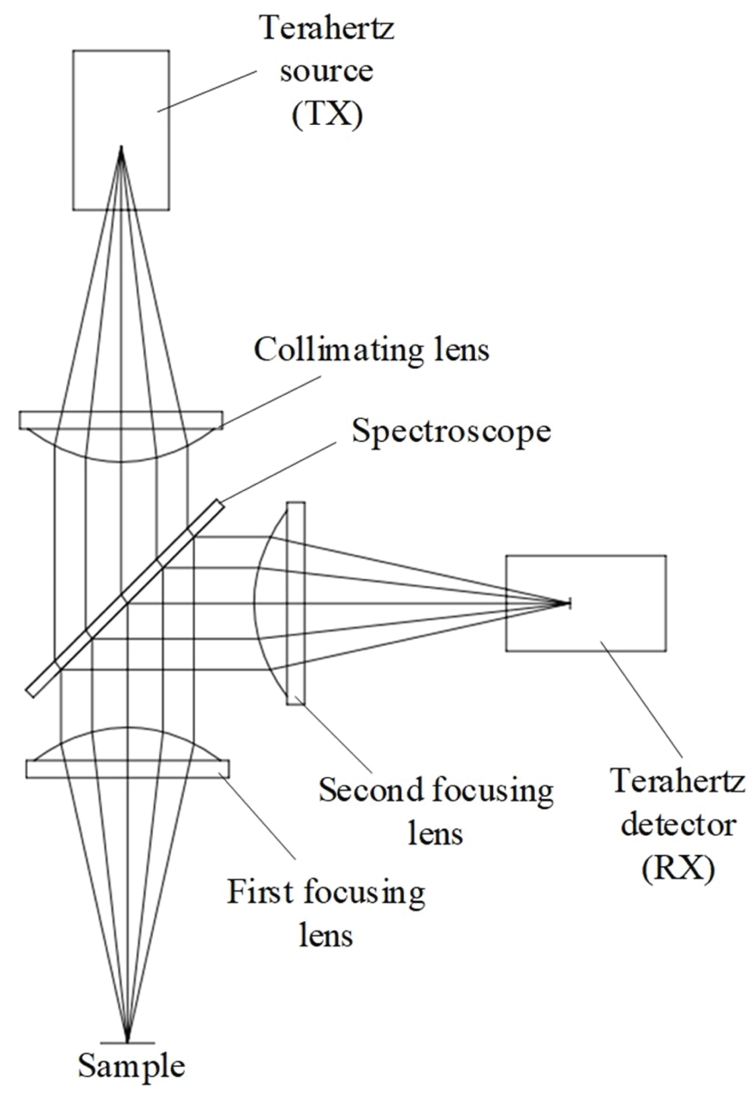
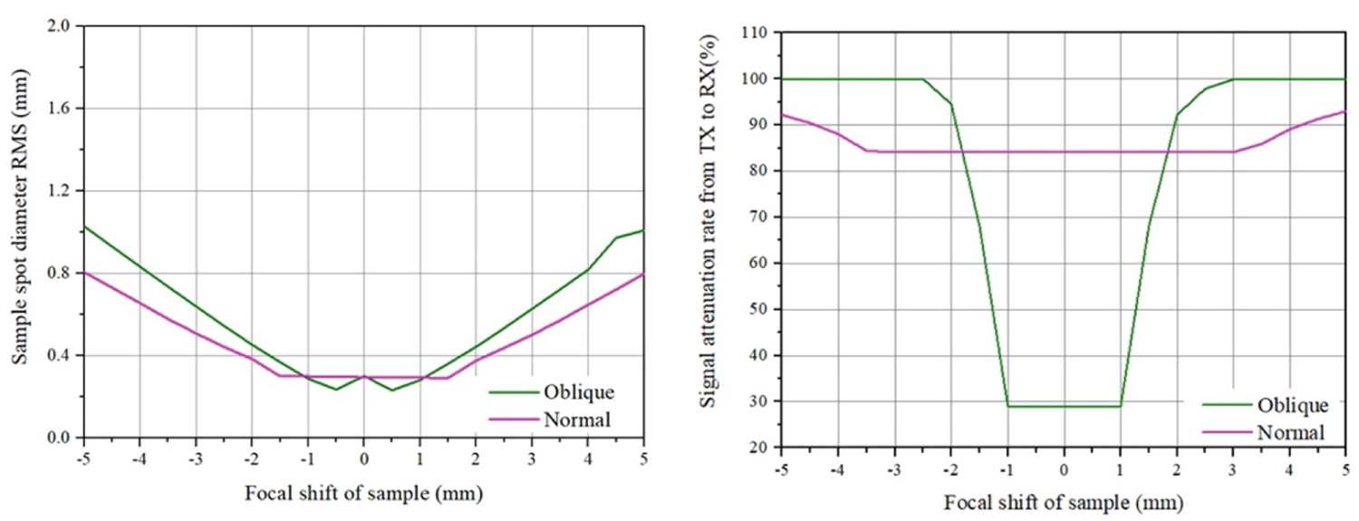
Figure 6: The curve of sample spot diameter and....
The curve of sample spot diameter and signal attenuation rate with focal shift.
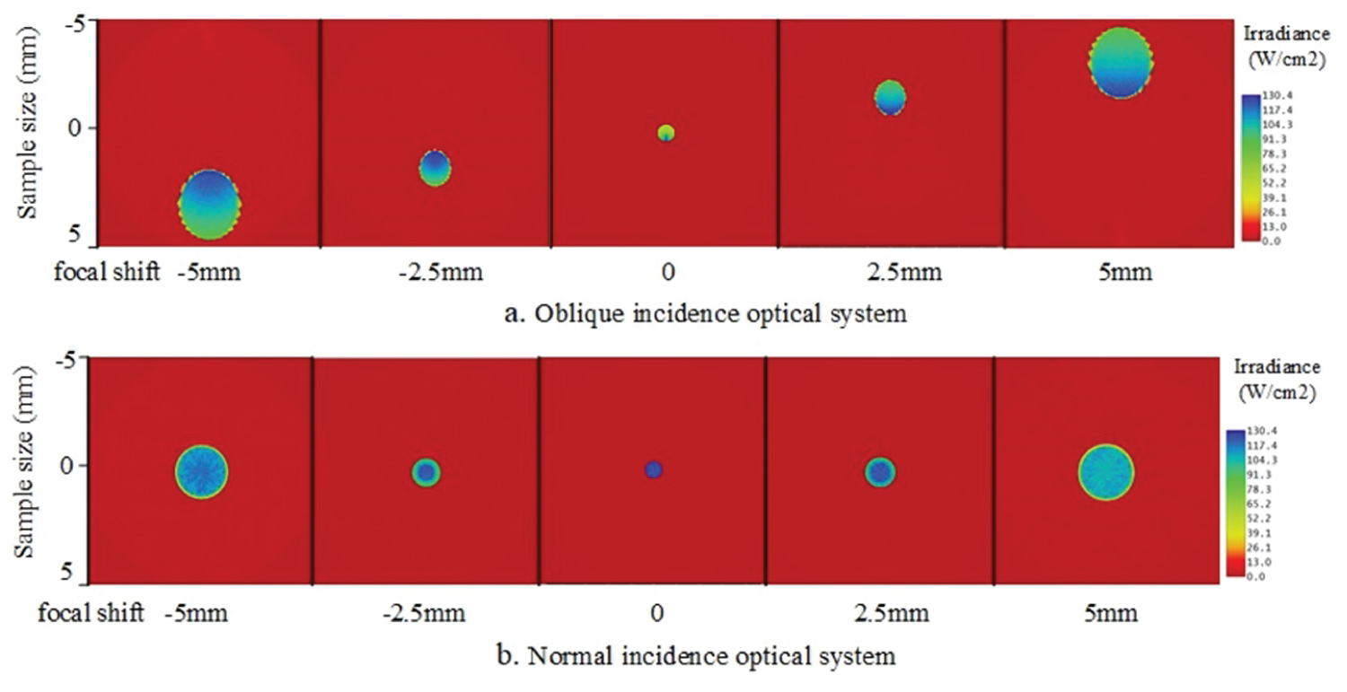
Figure 7: The illuminance diagram of the sample...
The illuminance diagram of the sample surface under different focal shift.
Tables
Table 1: Refractive index of TPX in the Terahertz band.
Table 2: Optical parameters of plano-convex lens.
References
- Liu Sheng Gang, Zhong Ren Bin (2009) Recent development of Terahertz science and technology and it's applications. Journal of University of Electronic Science and Technology of China 38: 481-486.
- Lavrukhin DV, Yachmenev AE, Yu Pavlov A, Khabibullin RA, Goncharov Yu G, et al. (2019) Shaping the spectrum of Terahertz photoconductive antenna by frequency-dependent impedance modulation. Semiconductor Science and Technology 34: 034005.
- Burford Nathan M, El-Shenawee Magda O (2017) Review of Terahertz photoconductive antenna technology. Optical Engineering 56: 010901.
- Zhai M, Locquet A, Roquelet C, Ronqueti LA, Citrin DS (2020) Thickness characterization of multi-layer coated steel by Terahertz time-of-flight tomography. NDT & E International 116: 102358.
- Mohan S, Odani N, Hossain MN, Feng H, Li Y, et al. (2020) Terahertz time of flight spectroscopy as a coating thickness reference method for partial least squares near infrared spectroscopy models. Analytical Chemistry 92: 3658-3665.
- Zhai M, Locquet A, Roquelet C, Citrin DS (2020) Terahertz Time-of-flight tomography beyond the axial resolution limit: Autoregressive spectral estimation based on the modified covariance method. Journal of Infrared, Millimeter, and Terahertz Waves 41: 926-939.
- Glyavin M Yu, Denisov GG, Zapevalov VE, Koshelev MA, Yu M, et al. (2016) High power Terahertz sources for spectroscopy and material diagnostics. Physics-Uspekhi 59: 595.
- Geng Bo Wu, Zeng Y-S, Chan KF, Qu S-W, Chan CH (2019) High-gain circularly polarized lens antenna for terahertz applications. IEEE Antennas and Wireless Propagation Letters 18: 921-925.
- Wu G-B, Zeng Y-S, Chan KF, Qu S-W, Chan CH (2019) 3-D printed circularly polarized modified fresnel lens operating at terahertz frequencies. IEEE Transactions on Antennas and Propagation 67: 4429-4437.
- Cheng Y, Fan J, Luo H, Chen F, Feng N, et al. (2016) Dual-band and high-efficiency circular polarization conversion via asymmetric transmission with anisotropic metamaterial in the terahertz region. Optical Materials Express 9: 1365-1376.
- Dai L, Zhang Y, O'Hara JF, Zhang H (2019) Controllable broadband asymmetric transmission of terahertz wave based on Dirac semimetals. Optics Express 27: 35784-35796.
- Guo S-J, Ruan C-J, Kong D-Y, Dai J, Zhang Y, et al. (2020) Research on terahertz transmission characteristics of nonpolar liquid based on frequency-domain spectroscopy. JOSA B 37: 1942-1947.
- Jingshi Z, Deliang Z, Yi Y, et al. (2018) Design of a quasi-optical system applied to terahertz imaging. Electronic Measurement Technology 41: 142-146.
- Sung S, Dabironezare S, Llombart N, Selvin S, Bajwa N, et al. (2017) Optical system design for noncontact, normal incidence, THz imaging of in vivo human cornea. IEEE Trans Terahertz Sci Technol 8: 1-12.
Author Details
Yujian Wang1*, Yongli Liu2, Bo Wang3 and Xinyong Zhu1
1Qingdao Quenda Terahertz Technology Co., Ltd., Shandong, Qingdao, China
2China Academy of Engineering Physics, Beijing, China
3Qingdao Shenghan Chromatograph Technology Co., Ltd., Shandong, Qingdao, China
Corresponding author
Yujian Wang, Qingdao Quenda Terahertz Technology Co., Ltd, Shandong, Qingdao, 266102, China.
Accepted: February 01, 2021 | Published Online: February 03, 2021
Citation: Wang Y, Liu Y, Wang B, Zhu X (2021) Design and Application of Optical System Based on Terahertz Time-of-Flight Imaging. Int J Opt Photonic Eng 6:029.
Copyright: © 2021 Wang Y, et al. This is an open-access article distributed under the terms of the Creative Commons Attribution License, which permits unrestricted use, distribution, and reproduction in any medium, provided the original author and source are credited.
Abstract
Using the penetration and transientness of Terahertz pulses and the photoconductive delayed detection method, the tomographic imaging of the interior of the object based on the time of flight can be realized. By comparing the transmittance of several crystals and polymers in the Terahertz band, Polymethylpentene (TPX) was selected as the material of Terahertz lens, and High Resistivity Float Zone Silicon (HRFZ-Si) as the material of beam splitter; By comparing the focal depth of normal incidence and oblique incidence optics system, the normal incidence optical system was used to realize time-of-flight imaging; Using the idea of optical-mechanical integration, the corresponding optical camera is designed according to the normal incidence optical system, and the peak-to-valley map and thickness map of the Lithium cobaltate coating of aluminum foil were obtained by time-of-flight imaging, and the defects such as complete shedding of the coating and uneven thickness were observed. The results show that the normal incidence optical system can realize Terahertz time-of-flight imaging and is applicable in the industrial nondestructive testing field.
Keywords
Terahertz, Time-of-flight imaging, Optical system, Industrial nondestructive testing
Introduction
Terahertz wave is a general term for a specific electromagnetic radiation, between microwave and infrared. In the field of electronics, it is also called millimeter wave or sub-millimeter wave. In the field of spectroscopy, it is also called far-infrared rays. The frequency of terahertz wave is between 0.1 THz ~ 10 THz, and the wavelength is between 0.03 mm ~ 3 mm [1]. Terahertz waves have sufficient penetrability for dielectric and non-polar materials such as plastics, ceramics, semiconductors, and so on. Therefore, terahertz waves can be used to detect the internal structures of objects to achieve non-destructive testing. Compared with X-ray and ultrasound imaging, the photon energy of terahertz wave is lower than X-ray and will not cause electromagnetic radiation to the operator or the object under detection. At the same time, the terahertz wavelength is shorter than ultrasound, which can achieve higher resolution of imaging.
Terahertz Time-of-Flight Imaging
The photoconductivity is a popular method to generate and detect terahertz wave [2]. On the transmitting side, a femtosecond laser pulse is used to excite the photoconductive crystal to generate photo-generated carriers. These photo-generated carriers generate instantaneously changing currents under the effect of a bias electric field and induce instantaneously changing terahertz pulses. On the detecting side, the detection of terahertz wave can be considered to be the inverse process of the generation process. The photoconductive crystal is excited by the femtosecond laser pulse to generate photo-generated carriers. These photo-generated carriers generate current under the action of the terahertz electric field. The magnitude of the current corresponds to the terahertz electric field intensity. Thus, the terahertz time domain pulse signal is detected by recording the intensity of the electric field [3] (Figure 1).
The terahertz wave generated by the photoconductivity is a transient pulse signal, and the typical pulse width of terahertz is approximately 1ps, therefore the terahertz pulse can be used for time-of-flight tomography [4,5]. For opaque multi-layer structures in the visible-light range, the penetration of terahertz waves can be used for non-destructive thickness detection, to achieve the transversal resolution of tens of microns (Figure 2).
The terahertz reference beam reaches the surface of the multilayer sample with a incidence angle . According to Fresnel's formula, part of the terahertz wave will be reflected at the interface of adjacent layers, and part of it will be refracted and continue to propagate through the sample. Reflection and refraction occur again at the next interface, so that the terahertz signal detected in a time delay window contains multiple reflection peaks, and the thickness of the sample can be calculated according to the time delay between two adjacent reflection peaks [6].
Where is the thickness of the jth layer sample; c is the speed of light in vacuum, which is 3 × 10⁸ m/s; , is the refractive index of the jth layer and the j-1th layer sample; is the delay time between the jth and j + 1th reflection peaks.
Terahertz Window Materials
The window materials used in terahertz wave mainly include High Resistivity Float Zone Silicon (HRFZ-Si) Polymethylpentene (TPX) High Density Polyethylene (HDPE), Picarin (Tsurupica).
In order to reduce the loss and dispersion of the optical system for terahertz signals, materials with high transmission coefficient and relatively stable refractive index in a wide frequency range are generally used to make terahertz lenses [7-9]. When electromagnetic waves interact with matter, the transmission coefficient can be given by the Fresnel formula [10-12]:
Where P respectively represent the situation that the polarization direction of the electromagnetic wave is parallel and perpendicular to the incidence plane, and satisfies the following relationship:
Therefore, materials with a large refractive index have low transmission coefficients and are not suitable to make lenses. Among the materials commonly used in the terahertz range, HRFZ-Si has a refractive index of 3.4, so it is generally used in photoconductive antennas to deflect light at a large angle range, also be used as a terahertz spectroscope due to its half-passing and half-reflected characteristics. HDPE has a low transmittance in the high frequency range, and there are obvious absorption peaks near 2.3 THz and 6.2 THz; Tsurupica and TPX have similar transmittance in the mid-to-high frequency range (> 0.75 THz), but the transmittance of Tsurupica is lower than TPX in the frequency range (≤ 0.75 THz), and the refractive index of TPX material in the terahertz range can be stabilized between 1.4559 and 1.4660, which can effectively suppress dispersion. In summary, TPX was selected as the material of the terahertz lens, and HRFZ-Si was selected as the material of the terahertz spectroscope (Figure 3 and Table 1).
Design of Optical System for Terahertz Time-of-Flight Imaging
Currently, the most widely used commercial Terahertz photoconductive antenna is MenloSystems' 1560 nm fiber-coupled antenna module. This article uses TERA15-TX-FC as a wide-range Terahertz source and TERA15-RX-FC as a Terahertz signal detector. The Terahertz beam divergence angle of TERA15-TX-FC is ± 12.5°, and the electrode gap on the crystal is 100 µm, while the TERA15-RX-FC's Terahertz beam acceptance angle is ± 12.5°, and the electrode gap on the crystal is 10 µm. Therefore, the Terahertz source and detector are the point source and point detector, and the divergence angle and reception angle are both ± 12.5°.
The TPX plano-convex lens is selected as the collimating and focusing lens. The parameters of the plano-convex lens are shown in Table 2. Two terahertz time-of-flight imaging optical systems are designed: An oblique incidence optical system shown in Figure 4 and a normal incidence optical system are shown in Figure 5. The incidence angle of oblique incidence optical system is 30° due to the limit of spatial layout. The HRFZ-Si spectroscope is used to split the terahertz wave in the normal incidence optical system.
The size of the spot focused on the sample can represent the lateral imaging resolution in the terahertz time-of-flight imaging optical system. The smaller the spot size, the higher the resolution, while the intensity of the terahertz signal received by the terahertz detector affects the signal-to-noise ratio of a single pixel [13]. Generally, the tested sample has multiple reflective surfaces with different depths in terahertz time-of-flight imaging, so it is necessary to ensure that multiple reflective surfaces are within the focal depth range of the optical system, and the greater the focal depth, the more stable the imaging quality [14].
Using Zemax's non-sequential mode, two optical systems of oblique incidence and normal incidence were established, and the two optical systems were compared with the sample spot size and the TX-RX terahertz signal attenuation rate by setting different focal shift of the sample reflection surface.
Figure 6 shows that the sample spot size of the normal incidence system is better than that of the oblique incidence system within the ± 5 mm focal shift. Although the signal attenuation rate of the normal incidence system is at least 83%, its variation with the focal shift is very gentle. While the oblique incidence system has a signal attenuation rate of only 28% without defocusing, but when the focal shift exceeds ± 1 mm, its value increases rapidly. When the focal shift exceeds ± 2.5 mm, its attenuation rate reaches 100%, and thus the detector cannot detect any terahertz signal. It can be found from Figure 7 that the position of the spot focused on the sample in the normal incidence system will not change with the variation of focal shift, and the shape can remain a perfect circle; while the position of the spot in the oblique incidence system will vary with the variation of focal shift, moving in the direction parallel to the incidence surface, and the shape of spot will also be distorted.
In summary, the focal depth of the normal incidence optical system can be maintained at ± 4 mm, which is better than the oblique incidence system. Large focal depths are more applicable when measuring multilayer samples. Therefore, the normal incidence system is selected as the optical system for terahertz time-of-flight imaging.
Testing of Terahertz Time-of-Flight Imaging
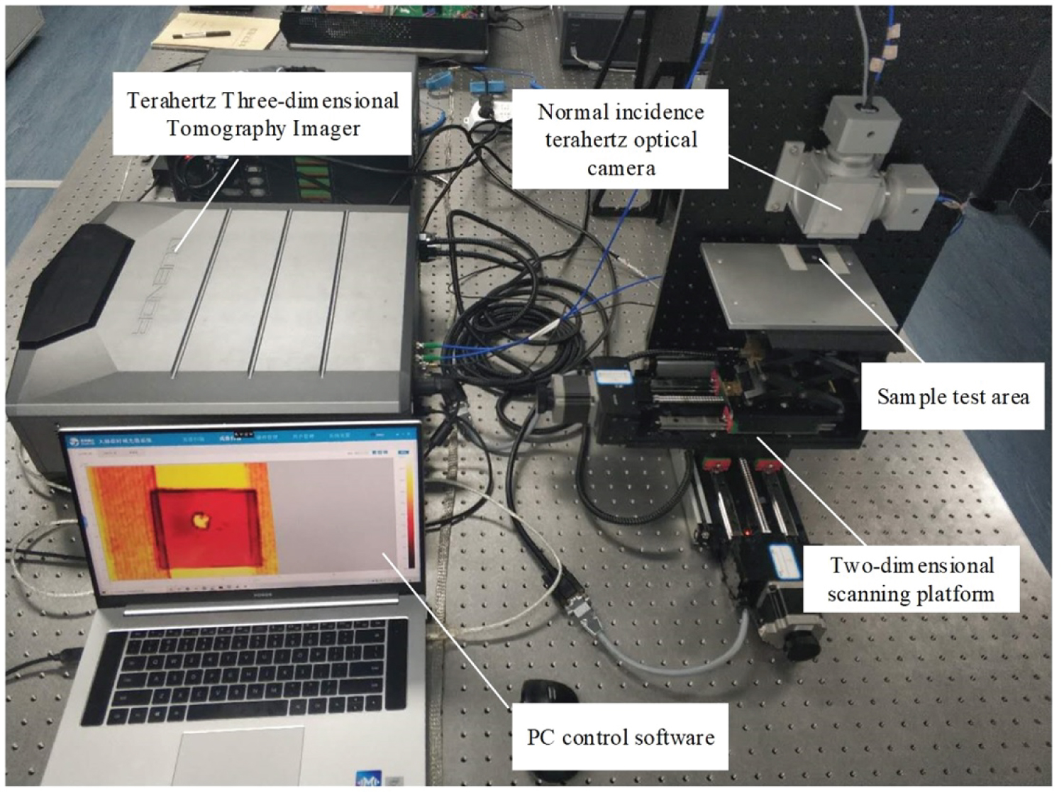
According to the layout of normal incidence optical system, corresponding opto-mechanical components are designed to form a terahertz camera for time-of-flight imaging. The terahertz camera is connected to the Terahertz Three-dimensional Tomography Imager containing a two-dimensional scanning platform to form a terahertz time-of-flight imaging test system. The equipment used in this test is the QT-TO1000 Terahertz Three-dimensional Tomography System independently developed by Qingdao Quenda Terahertz Technology Co., Ltd (Figure 8).
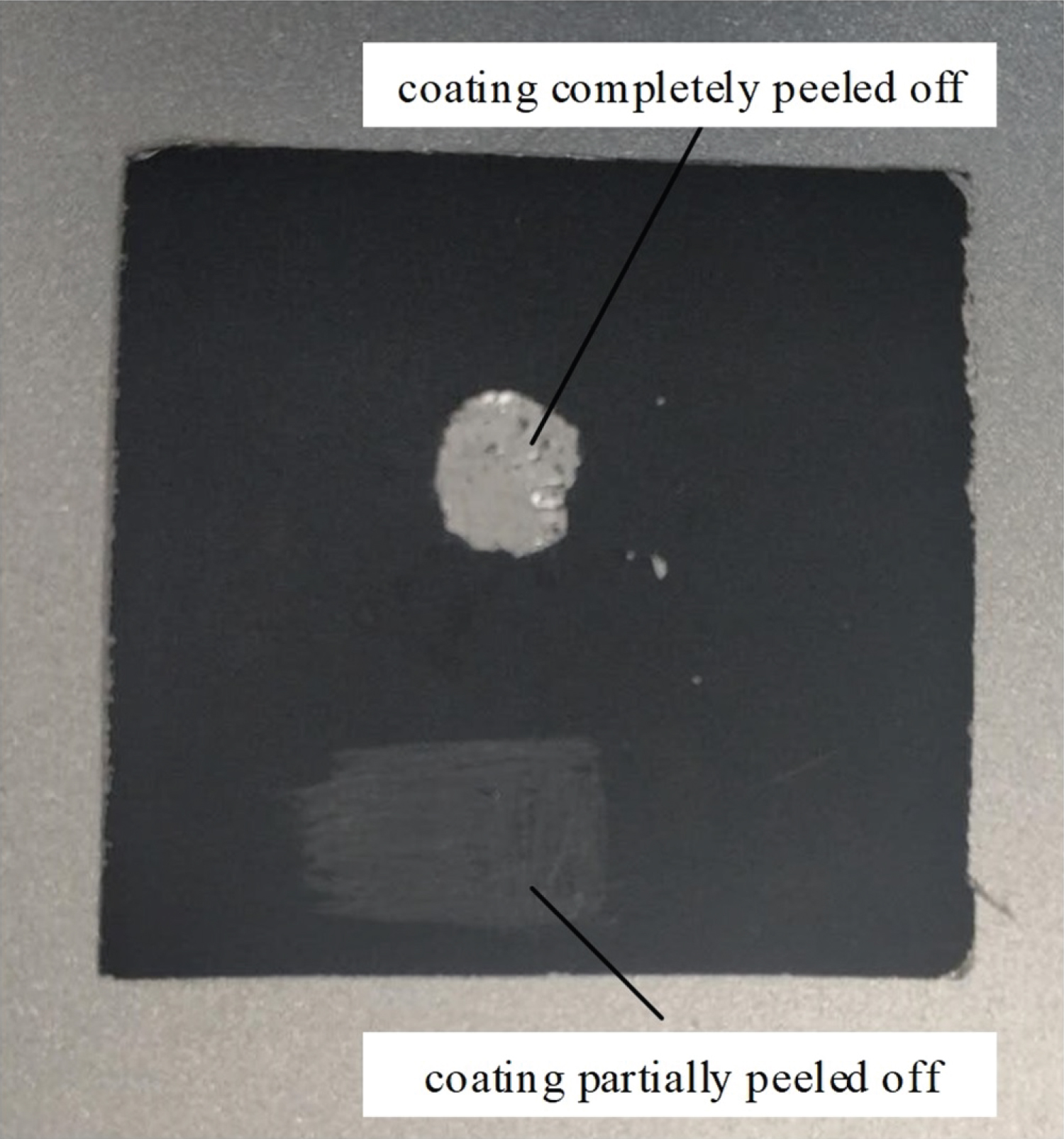
The aluminum foil coated with lithium cobaltate is the testing sample. The sample size is 36 × 35.5 mm. There are two defects in the surface coating. One area of the coating is completely peeled off, and another area of coating is partially peeled off. The refractive index of lithium cobaltate in the terahertz range is 2.28. The testing sample is fixed on the sample stage with paper tape (Figure 9).
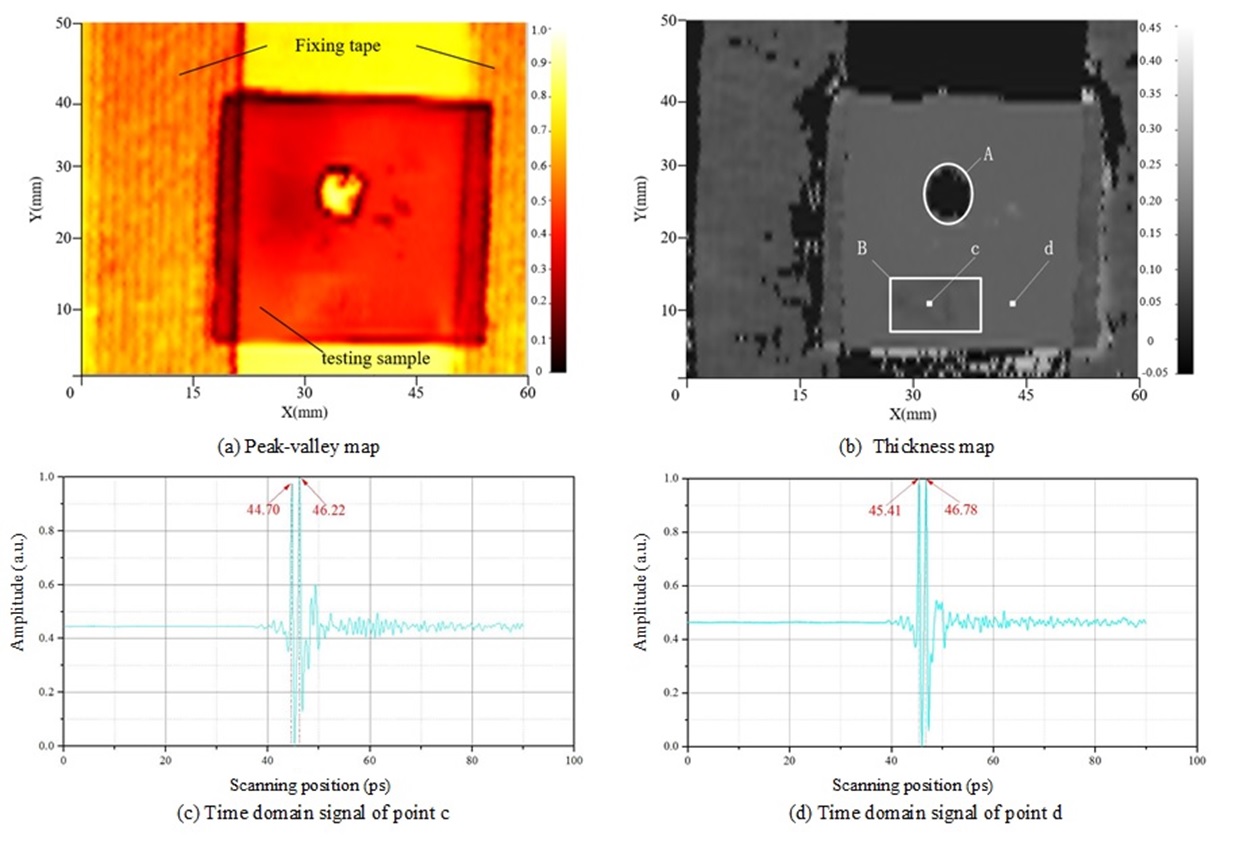
The imaging test result is shown in Figure 10. The intensity of each pixel in the peak-valley map is the peak-valley difference of the corresponding terahertz signal (normalized here). In the peak-valley map, the sample outline and the coating completely peeled off can be observed clearly. Each pixel in the thickness map is the thickness of the coating at that point calculated according to Eq. (1). In the thickness map, the coating completely peeled off (area A) and the coating partially peeled off (area B) can be observed, the thickness of the complete coating is 100.0 µm, and the thickness of the coating in area B is between 81.0 ~ 93.0 µm. Selecting point c in the area B with the coating partially peeled off and point d in the area with the complete coating, the single-point terahertz time-domain signal curves are obtained. The thicknesses calculated according to Eq. (1) are 90.1 µm and 100.0 µm, consistent with the thickness map.
Conclusion
The imaging based on terahertz time-of-flight can realize non-destructive thickness measurement and defect detection of multilayer objects. The normal incidence optical system and the terahertz camera can sufficiently achieve this function and the longitudinal resolution can reach the level of 1 µm. The work in this paper is important for the application of terahertz technology in the field of industrial non-destructive testing. More samples are required to be measured by the system in the future.