International Journal of Atomic and Nuclear Physics
(ISSN: 2631-5017)
Volume 4, Issue 1
Original Article
DOI: 10.35840/2631-5017/2515

Article Formats
Diffusion Cloud Chamber in Education
Table of Content
Figures
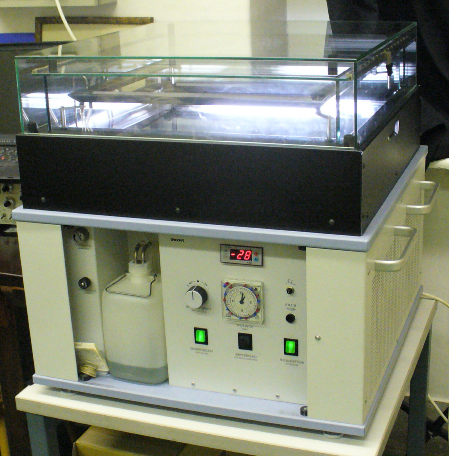
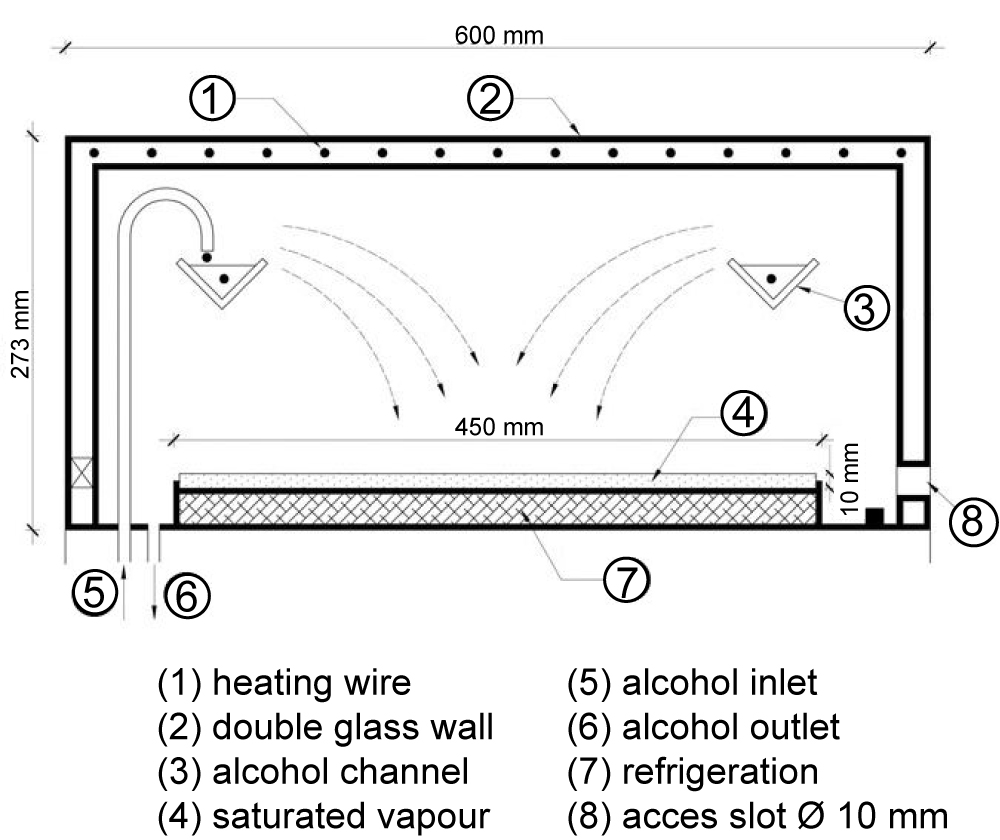
Figure 2: The scheme and mode of operation of the...
The scheme and mode of operation of the diffusion cloud chamber.
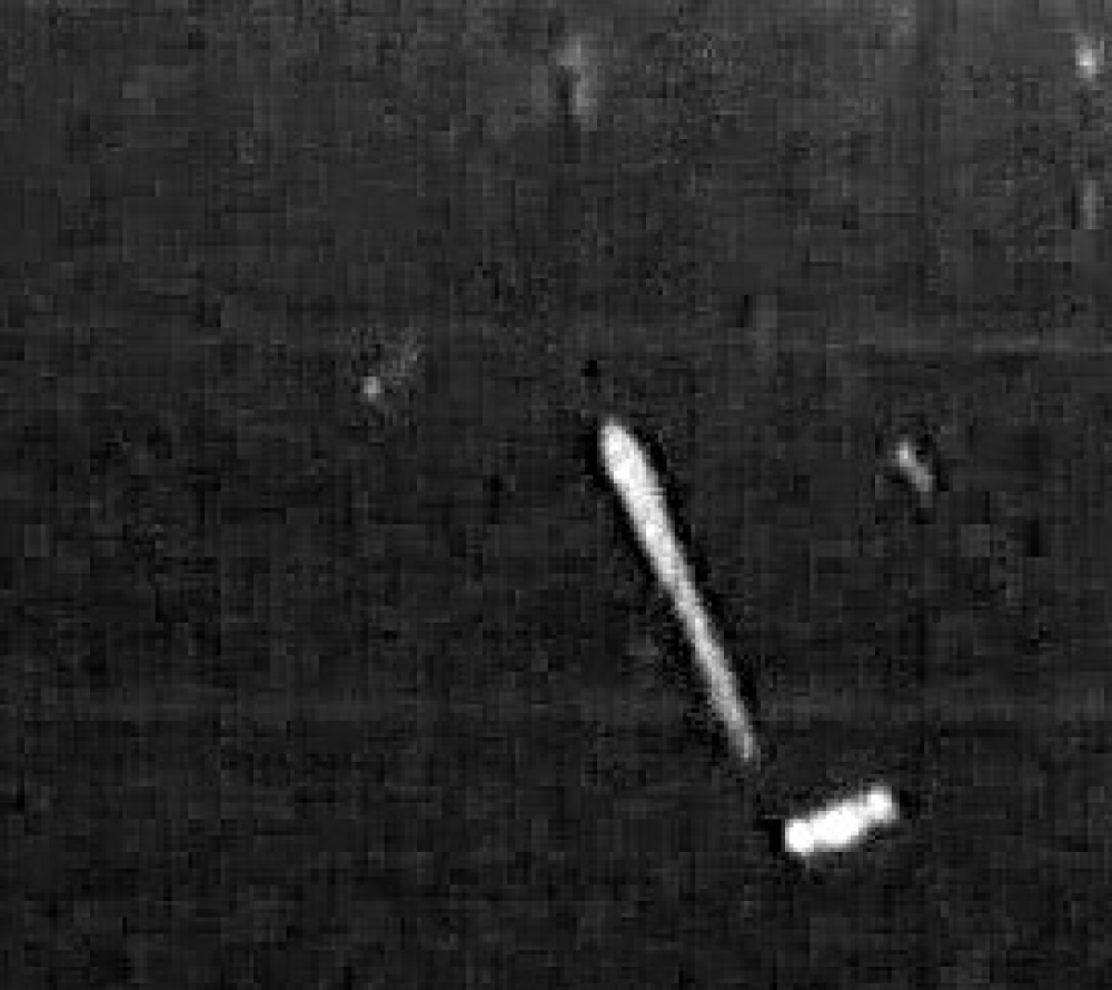
Figure 3: Broadening of the alpha-particle's track at the...
Broadening of the alpha-particle's track at the end of the path.

Figure 4: Decay chains of 238U - 226Ra and Th(B+C) in...
Decay chains of 238U - 226Ra and Th(B+C) in series of 232Th - 228Th [8].
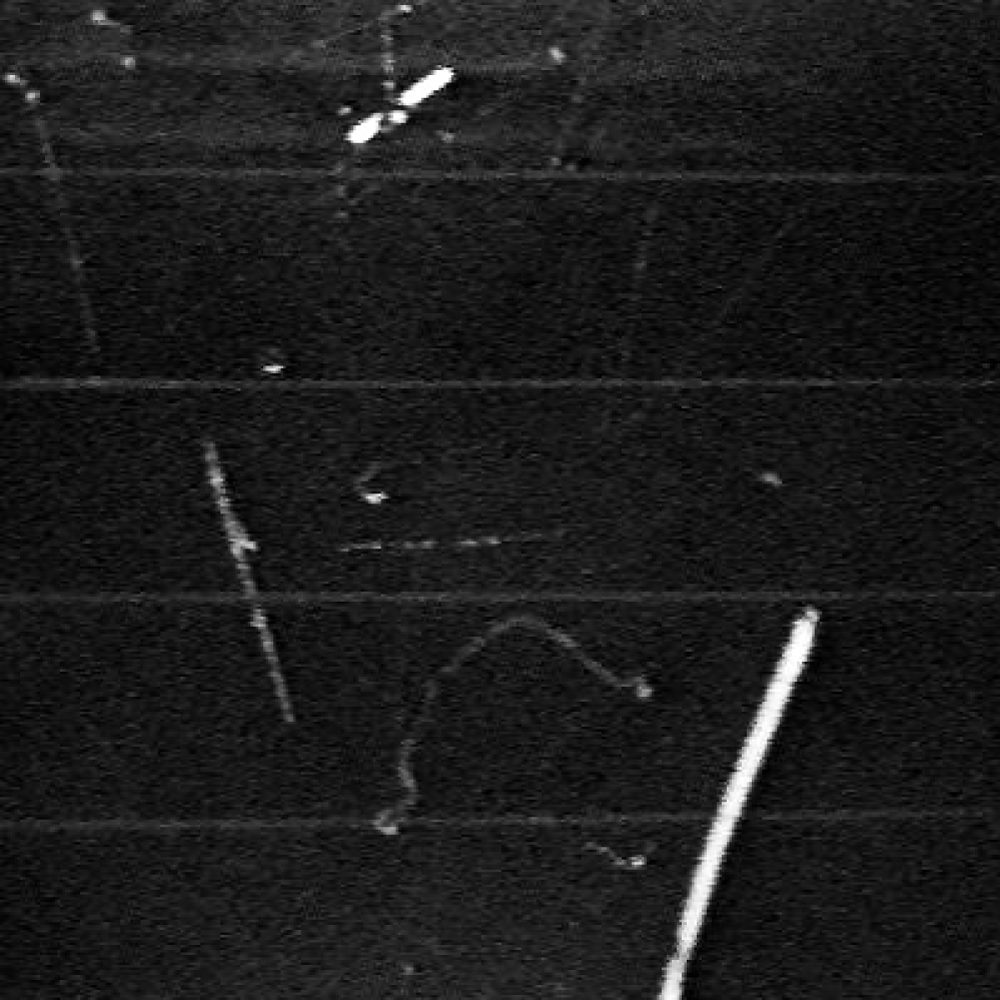
Figure 5: Background radiation tracks in the diffusion...
Background radiation tracks in the diffusion cloud chamber.
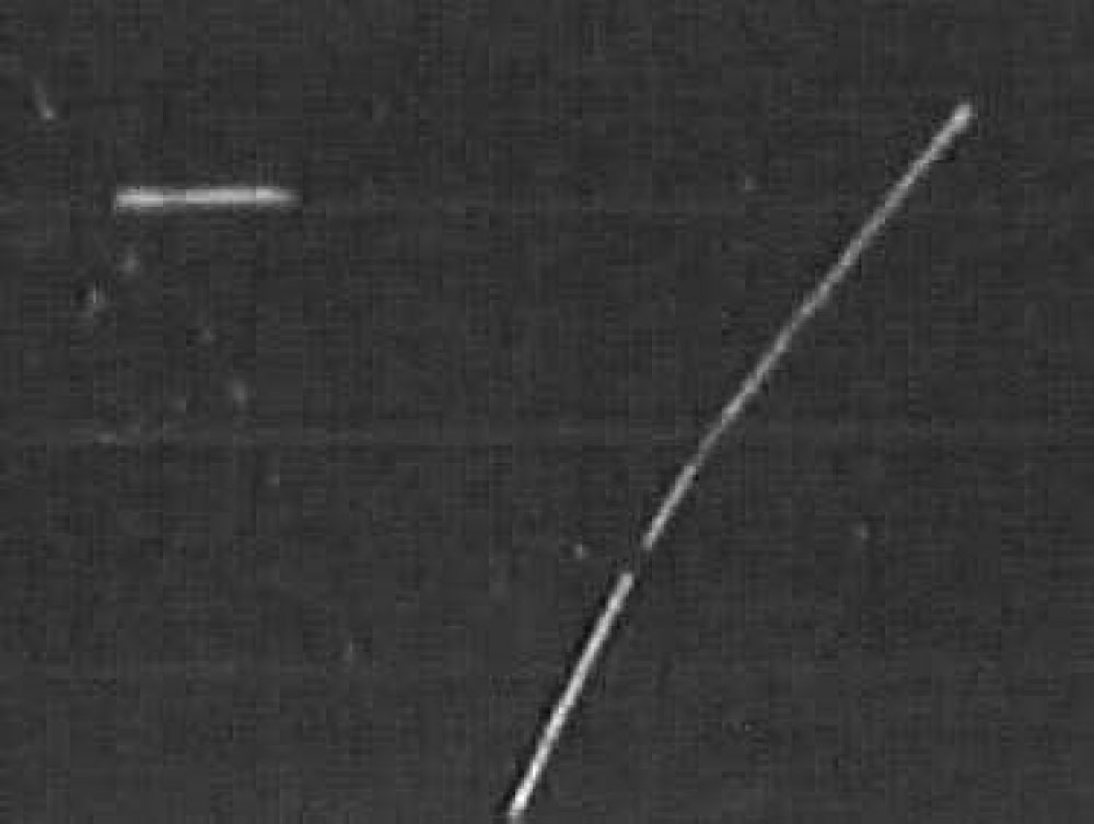
Figure 6: Background muon in the cloud chamber...
Background muon in the cloud chamber (Upper left: alpha-particle).
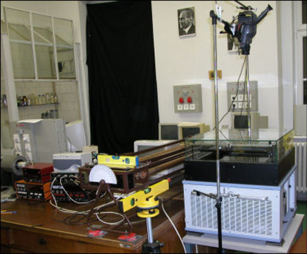
Figure 7: Experimental arrangement for muon observation....
Experimental arrangement for muon observation.
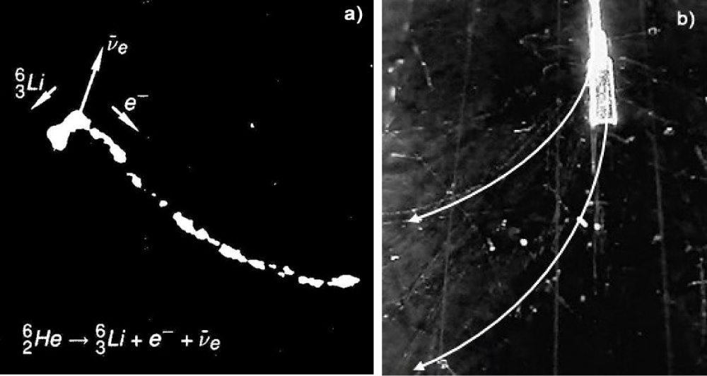
Figure 8: Deflection of β-particles in magnetic field...
Deflection of β-particles in magnetic field.
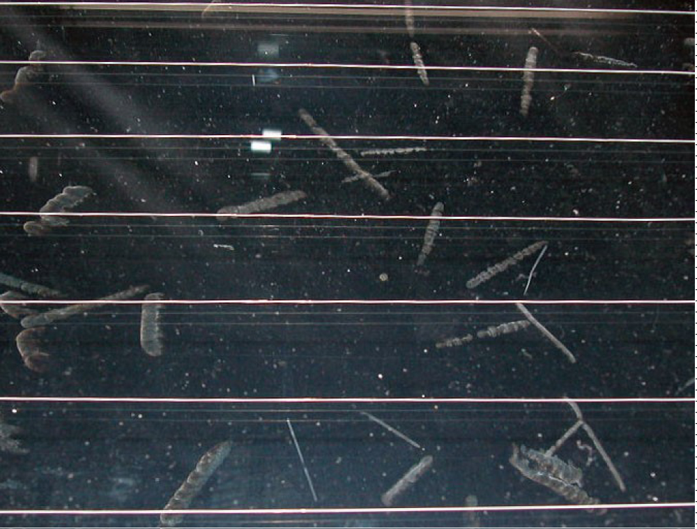
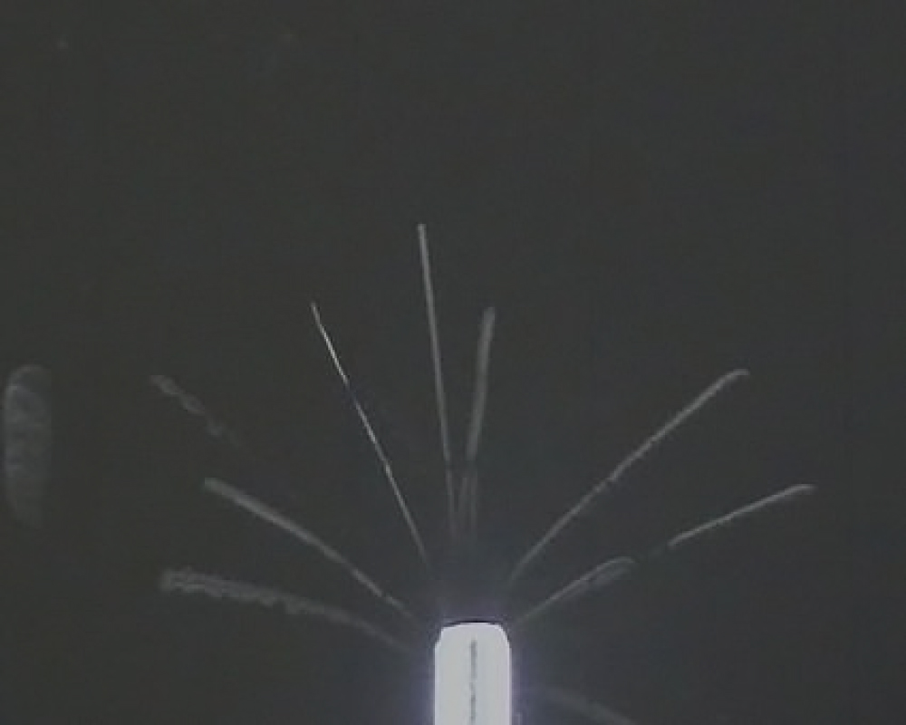
Figure 10: Alpha-radiation from radon gas collected...
Alpha-radiation from radon gas collected from air.
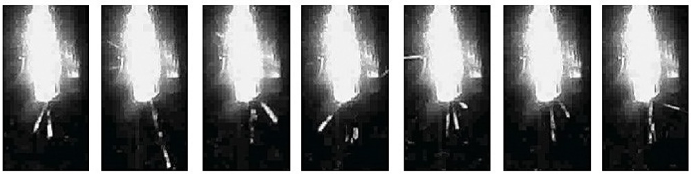
Figure 11: Rutherford-scattering of Th(B+C) alpha-particles...
Rutherford-scattering of Th(B+C) alpha-particles on Ag-foil.
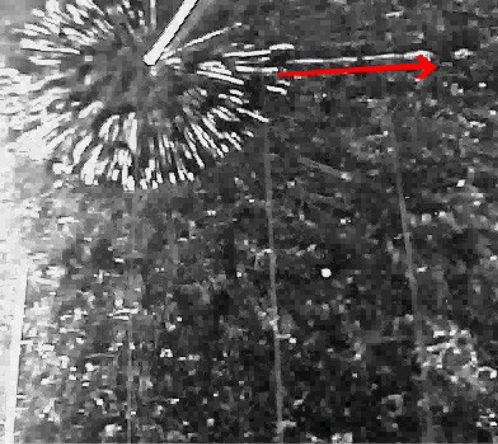
Figure 12: 14N(α, p)17O reaction induced by α-particles...
14N(α, p)17O reaction induced by α-particles from the Th(B+C) source.
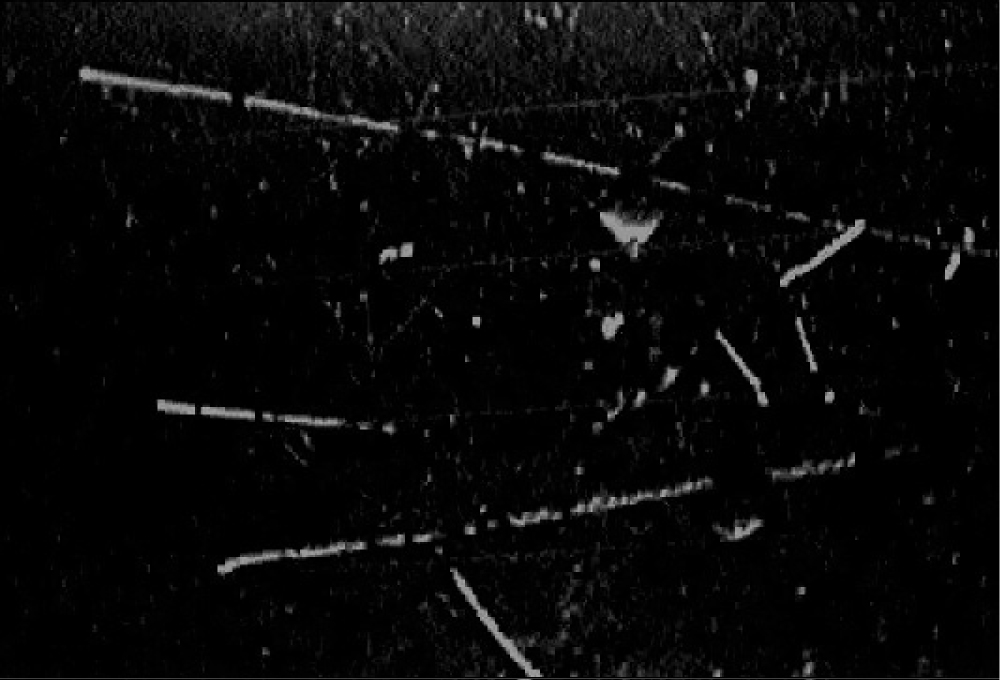
Figure 13: Tracks of protons hit by 239PuBe source neutrons...
Tracks of protons hit by 239PuBe source neutrons coming from right.
Tables
Table 1: The applied sources and their characteristics (The most intensive radiations are listed, only).
Table 2: Deflection of the 90Sr-Y source's beta-particles in magnetic field of B = 0.240 Tesla.
Table 3: Comparison of α-ranges (mm) determined with different methods.
Table 4: Comparison of the 212Pb half-life determined in different ways.
References
- Csikai J, Szalay A (1957) The recoil effect of the neutrino in the beta-decay of 6He. Int. Conf. on Mesons and Recently Discovered Particles, Padova-Venezia, 467-475.
- Sajó-Bohus L, Barnaföldi GG, Halász G, Hernáth Sz, Horváth á (2002) Educational Cloud Chamber To Improve Nuclear Literacy.
- Visualization of radioactive particles/Diffusion cloud chamber. PHYWE series of publications.
- Burcham WE (1963) Nuclear Physics (McGraw-Hill, New York).
- Fényes T (2009) Nuclear physics. (2nd edn), Kossuth Publishing Corporation, Debrecen.
- Győrfi T (2011) Nuclear physics in education. University of Debrecen.
- (1999) Chart of Nuclides, NNDC.
- (1998) Gamma-Ray Spectrum Catalogue. (4th edn), Idaho National Engineering & Environmental Laboratory, γ-Ray Spectrometry Center.
- https://www.britannica.com/science/nuclear-reaction.
- Ziegler J (2000) SRIM The Stopping and Range of Ions in Matter.
- http://falcon.phys.klte.hu/~raics/TAVTANULAS/.
Author Details
Tamás Győrfi1* and PéterRaics2
1Eötvös József College, Hungary
2Institute of Experimental Physics, University of Debrecen, Hungary
Corresponding author
Tamás Győrfi, Eötvös József College, Baja, Hungary.
Accepted: October 14, 2019 | Published Online: October 16, 2019
Citation: Győrfi T, Raics P (2019) Diffusion Cloud Chamber in Education. Int J At Nucl Phys 4:015.
Copyright: © 2019 Győrfi T, et al. This is an open-access article distributed under the terms of the Creative Commons Attribution License, which permits unrestricted use, distribution, and reproduction in any medium, provided the original author and source are credited.
Abstract
Radioactivity and the accompanying ionizing radiations are important part of the environment. They cannot be observed by humans. However, with the cloud chamber everyone can easily see that the radiations are really present in our environment.
Using cloud chambers in public education students are able to gain direct experiences in many fields like natural and artificial radioactivity, characteristics of the particles, features of the quantum world, random nature of the processes as well as the unity of classic and contemporary physics. Pictures, videos, descriptions and computer codes assisting the evaluation may be really useful in lessons and in different studies including university education.
PHYWE made diffusion cloud chamber has originally been developed for demonstration. Our aim was that besides showing spectacular tracks also interesting measurements could be performed.
Keywords
Diffusion cloud chamber, Ionizing radiations, Background radiation, Alpha-particle, Radon, Rutherford-scattering, Half-life
Introduction
We know many types of radiation detectors. However, the cloud chamber was the first tool which could visually show the track of the particles. These tracks give information about the type, electric charge, momentum and energy of the particles.
Based on their operation cloud chambers can be divided into two groups. In the expansion or Wilson-type device (1911, Nobel prize in 1927) the necessary super saturation of vapor is achieved by a sudden expansion of a rather large volume where the nuclear processes may take place. It can work in a pulsed regime, only. The 3D particle tracks in this expansion cloud chamber are recorded on stereo-photos by a short flash like in the famous Csikai-Szalay neutrino experiment [1].
Steady temperature-gradient of limited height within a vessel serves as the basis of the diffusion cloud chamber's operation (Langsdorf 1939) which allows permanent observation.
Cloud chambers were used in nuclear-and particle-physics research until the end of the 1950s. However, they can be applied perfectly for educational and demonstrational goals even at present [2].
In this paper the operation and characteristics of a PHYWE-made diffusion cloud chamber [3], developed at the University of Göttingen (Germany) for demonstration purposes are described. Experiments with radiations from different nuclear processes and their evaluation with appropriate programs are also presented.
Experimental
Diffusion cloud chamber
For the demonstration of background and artificial radioactive radiations as well as other nuclear processes a PHYWE made large diffusion cloud chamber [3] was jointly installed and utilized by the Institute for Nuclear Research, Hungarian Academy of Sciences, Debrecenand the Institute of Experimental Physics of the University of Debrecen (Figure 1).
Construction and operation
The construction operation fundamentals of the diffusion cloud chamber can be seen in Figure 2. Isopropyl alcohol (C3H8O) is vaporized in the upper part of the chamber and condensed to the black base plate cooled to -28 ℃ by a refrigerator. Supersaturated layer is formed over the liquid phase. The electrically charged particles passing through this sensitive volume produce tracks from the cloud. The height of the active horizontal layer was determined by alpha-particles to be ~10 mm. The details of the construction and operation of the 45 × 45 cm2 active area device are published in [3].
Track formation
In a diffusion cloud chamber the tracks give information about the type and energy of the particles. In the saturated layer the pressure of the alcohol can reach the multiple of the saturation pressure belonging to the given temperature. If the ions developed along the path enter this area the steam condenses in the form of small drops and the particle track becomes visible. The formation of the cloud drops grown to a visible size is defined by the degree of saturation. The following conditions should be fulfilled [4]:
in case of a neutral particle: (1)
in case of charged particle: (2)
where PE: Equilibrium steam pressure (Pa), ρ: Density of the material(kg•m-3), T: Temperature (K), R: Gas constant (J•kg-1•K-1), ε: Dielectric constant, f: Surface tension (N•m-1), r: Radius of the droplet(m). Charged particles initiate cloud drops earlier than neutral ones.
The radiation leaves "cloudline-like" track in the chamber. It is similar to the phenomena when an airplane flies at a height where it cannot be seen but the vapor 'condensation line'.
The visible length of the particle track may be equal to the physically determined dimension only if the velocity vector is parallel with the sensitive layer, ie. horizontal.
Dead time
The dead time of the chamber is caused by the disappearance of the alcohol vapor from the track volume by condensation. A "black track" is then shown in the surrounding cloud inhibiting the formation of a new track as long as the supersaturation is reestablished locally again. High activity Th(B+C) source was utilized producing α-tracks in the chamber equipped with a camera. The video records were then analyzed and counted the frames on which no tracks had been seen at the same location. By the number of these images and the frame rate made it possible to determine the dead time resulted in an average value of ~ 1 s.
Particles in the Chamber
Slowing down and stopping
Ionization along the path is described by the Bragg-curve, which shows the number of ion pairs on one unit path length X. Specific energy loss dE/dX of heavy charged particles can be calculated with the formula of Bethe and Bloch [5]:
where vi, Zi are the ion velocity (m•s-1) and charge (C) while Zm, ρm, Am denote charge, density (kg•m-3) and atomic weight (kg) of the stopping material. For decreasing velocity the ionization and thus the energy loss increase. This can be seen when the track of the particle broadens at the end of the path (Figure 3). It is useful to determine the direction of the flight.
At a distance R the energy of the particles becomes zero being the range of radiation. It is proportional to the particle energy.
Recording and evaluation of particle tracks
Still as well as motion pictures were recorded by different cameras. The best results could be achieved by the classical video tape recorder or its modern versions posterior digitalized for evaluation. Quantitative experiments (activity, half-life) with simple web cams may suffer from the inaccurate timing and frame counting caused by different compression methods.
Particle identification may be carried out by the differences in the geometry and thickness of their tracks. Short, thin zig-zag path refers to low energy electrons (beta-particles) while longer, thick straight ones characterize heavy charged particles (e.g. protons, 4He++-ions). Muons are similar to the latter type but with thinner and slightly curved path. (Quantitative evaluations for γ-radiation is quite difficult in cloud chambers).
Energy of the particles can be determined measuring track length. Energy distribution and range-energy dependence can be calculated from the data. From the thickness of the tracks the stopping power of the particles can be deduced. Another way for particle discrimination and energy determination is their different absorption in various materials.
We have developed an image processing code [6] for the evaluation of the video recordings and pictures of radiations. The program (hence forward GGP) finds the particle tracks in a marked area of the compressed "avi" and "bmp" files on the basis of the colors of the pixels. It determines their start and end co-ordinates to calculate the length. The number of pixels constituting the particle path gives the surface area of the given track, while the ratio of the surface area to the length gives the width.
The free Lince software was also applied to measure the track length and to check our own program.
Radiation Sources
Tracks of radiations from artificial radioactive sources
Particles from different sources (Table 1) were shot into the sensitive volume through the access slot of the chamber. Many experiments were performed with α-particles from a Th(B+C) emanating preparation. Alpha tracks of 222Rn, 241Am, 235,238U and 232Th were also displayed. A 90Sr/Y source was utilized for production of β-rays. A 239Pu-Be neutron source allowed to demonstrate the (n,p) scattering. Most of the radioactive sources may produce also gamma-rays.
The measurement of ranges makes it possible to determine the energy of the particles. Unambiguous experimental circumstances might be produced for α-particles, only, because their tracks are best visible in the cloud chamber. Most of the experiments referred below have been performed by Th(B+C) source. Its decay series together with a portion that of 238U can be seen in Figure 4.
Experiments with the Diffusion Cloud Chamber
Observation of the natural background
Utilization of background radiations from natural radioactivity is the simplest solution for demonstrations. Decay products of the radon and its daughters originating from U and Th supplying α- and β-particles in Figure 5. Cosmic-ray muons (Figure 6) are also detectable if they fly in the horizontal direction.
Muon identification
For the identification of muons in the cloud chamber a telescope equipped with two GM-tubes of 890 mm length and 40 mm in diameter were applied. Co¬incidence condition was electronically established between the counters to select events when a particle crosses both detectors simultaneously. If this was met then a click sounds and the event has been counted. The system was located parallel with the sensitive volume of the cloud chamber (Figure 7).
A video camera recorded the scene in the chamber continuously. Coincidence between the sound from the telescope and the event on the display indicated a muon intercept through both devices. Since in the horizontal direction the thickness of the air as well as the other absorbers (walls) is high and the detector efficiencies were rather lows the number of mutual coincidences was very limited giving hardly acceptable statistics. The conclusion was the experiment should be repeated in better conditions.
Deflection of β-particles in magnetic field
Particles in magnetic field makes possible the determination of their specific charge for identification. Experimental difficulties arise from the geometry of the cloud chamber making impossible to apply strong electromagnet from outside. The only solution was to place rare earth metal magnet (of dimensions 1.2 × 5.0 × 0.45 cm3) into the sensitive volume having rather limited field strength (B~0.24 T).
Since Compton-scattered electrons would produce many disturbing tracks beta-particles from a 90Sr/Y source were selected having no γ-rays in the decay.
There were two problems which obstructed the demonstration easily perceptible. The magnetic field covered a small area of the chamber therefore the total deflection of the trajectory is in Figure 8 by the Lorenz-force was small. The two energy groups of the β-source source with their continuous shape made the clear observation also difficult. To verify the effect the direction of the magnetic field was reversed. Utilization of also a positron source would make the demonstration more expressive.
a) Photo of the historical Csikai-Szalay experiment on the indirect observation of the neutrino in expansion cloud chamber.
b) Deflection of 90Sr beta-particles in the diffusion cloud chamber.
In Figure 8b the source can be seen above, and the magnet in front of it. The parallel lines are the heating wires of the chamber. The deflection happened to the left and the tracks are shown by the artificial enhancement lines.
Magnetic deflection can be calculated with the help of the following relations. Relativistic formula:
Non-relativistic formula:
Where m0c2: Electron rest energy (J), e: Elementary charge (C), B: Magnetic induction (T), r: Radius of circular track (m). The deflection radius concerning the two groups' maximal energy was calculated in Table 2 with the relativistic formula (4).
Radon (222Rn) in the cloud chamber
To observe (up to 99.9%) mono energetic alpha-particles the cloud chamber was filled with 222Rn-gas of activity 180 kBq collected from a 226Ra source (Figure 9). Length of the tracks varies because of the earlier mentioned geometric effects.
Sometimes characteristic V-shaped tracks can be seen (even in natural background), due to two alpha-decays following each other within dead time. They can originate from mother-daughter-relationship isotopes or two entirely independent decay events which accidentally take place near each other.
The radon content of a room can be simply investigated by the collection of its daughter nuclides. Air was pumped through a multilayer filter paper with a vacuum cleaner for an hour. Aerosols with radon (mainly 222Rn) and its daughter nuclides formed a short-lived source giving tracks presented in Figure 10.
Observation of nuclear reactions
The Rutherford-scattering experiment proving the existence of the nucleus initiated a new scientific era. We considered its demonstration very important with the help of the diffusion cloud chamber. The α-beam of the Th(B+C) source had to be collimated to show the deflection clearly (Figure 11). We have applied silver foil because it can be handled easier in the cloud chamber. Due to the energy loss both in the air and the Ag-foil the initial energy and track length decreased significantly.
The existence of the nucleus would be shown unambiguously by backscattering. Angles greater than 90 degrees may not be studied in the recent geometry. However, as a demonstration, it is important to see the significant deflections in Figure 11 which prove the scattering process.
Applying high intensity Th(B+C) source the α-particles create a circular formation of tracks ("halo"). Sometimes a longer and thinner track can be seen which stems from a proton originating from the nuclear reaction as seen in Figure 12. It is a reproduction of the well- known and famous experiment on the first nuclear reaction made by Rutherford in 1919 [7-9]. The very short path of the nucleus 17O cannot be observed on the records because of the large α-background.
Neutrons cannot be observed directly in the cloud chamber. It is possible indirectly, only, by means of charged particles or γ-radiation produced in nuclear reactions. A 239PuBe-source of neutrons of about 5.5 MeV average energy was applied in our experiment. The (n,p) elastic scattering of the neutrons on the hydrogen nuclei of the chamber's vapor may be observed in Figure 13 as straight lines (together with the randomly oriented tracks of the background α-particles).
Range of charged particles
Measurement of ranges makes it possible to determine the energy of the particles. Unambiguous experimental circumstances might be produced for α-particles, only. Table 3 summarizes the ranges from measurements with Th(B+C) source evaluated by our program GGPas well as by the Lince off-line software. Calculated values are also listed which have been produced by the SRIM 2010 simulation code [10] and an empirical expression [5]:
where Rα: Range of charged particles (cm), Eα: Energy of charged particles (MeV).
SRIM results are shown for "air" and an "air+10% propanol" composition at normal temperature and pressure. The measured values evaluated by GGP are in good agreement with the simulation for the composite gas. The random error of the measurements is estimated to be 10%.
The relative statistical uncertainty of the measured data in case of the "manual" Lince program is about ± 5.5%, while in case of the GGP is about ± 12%. However, our evaluated range values are closer to the semiempirical calculations. The results may indicate the medium is a mixture.
Determination of half-life
For this experiment the nuclide 212Pb (T1/2 = 10.64 h) from the Th(B+C) source was used. The α-tracks have been observed for two days and the images were recorded in every hour for 2 minutes. Our image processing program counted the tracks of α-particles in the given frames. The results were plotted as a function of time in the Excel program. An exponential trendline was fitted to the diagram and the half-life was determined from relation (7). As a control we have counted the particle tracks manually, too.
where I, I0: Number of tracks, λ: Steepness, t: Time (s), T1/2: Half-life (s).
A further check with α - and γ-spectrometry as well as β-counting were also applied. The results are listed in Table 4. Data of the cloud chamber have the highest deviations from the literature. It can be explained by the low statistics and the resulting huge statistical uncertainties.
Summary
The large diffusion cloud chamber can be used efficiently for different phases in the physics teaching: Grammar and secondary schools, university. In primary education the cloud chamber can be utilized mostly as a demonstrational tool: Material structure, background radiation.
In secondary education the cloud chamber is important in teaching nuclear physics, radioactivity (e.g. determining half-life). Observation of the scattering processes, production of new particles, the possibility of transmutation offer delightful experience for the students, e.g. 14N(α,p)17O nuclear reaction. With the collision of particles (e.g. n-p scattering) students can master classical mechanics. When evaluating the experiments statistics and uncertainties come to light. Teaching physics at universities the diffusion cloud chamber can be used for determining half-life, stopping power and range of charged particles, energy spectra from track length distribution, observation of nuclear reactions, statistical behavior of nature.
Utilization of the expensive but outstanding large diffusion chambers in education and civil knowledge distribution may be best performed centrally with internet support for live experiments. Real time observation is planned to be introduced in the future by a web-camera having IP-number which will be accessible through our web-site [11].
The information related to the diffusion cloud chamber and the theoretical foundations, which are necessary to the understanding of certain phenomena of nuclear physics can be found also on our website [11]. There are descriptions, animations, picture and video databases. Based on guidelines there is the opportunity to work up the data of certain experiments individually or in groups. We plan that with the help of an IP camera providing webcast live monitoring of the processes will be possible. This is important since such resources and solutions can be applied at laboratory conditions, only.