Analytical Solution of the Stationary Subcritical Flow of a Gaseous Coolant in the Branches of the Heat Exchange Pipelines of the Apparatus
International Journal of Healthcare Systems Engineering
(ISSN: 2633-8939)
Volume 3, Issue 1
Original Article
DOI: 10.35840/2633-8939/7207

Article Formats
Analytical Solution of the Stationary Subcritical Flow of a Gaseous Coolant in the Branches of the Heat Exchange Pipelines of the Apparatus
Table of Content
Figures
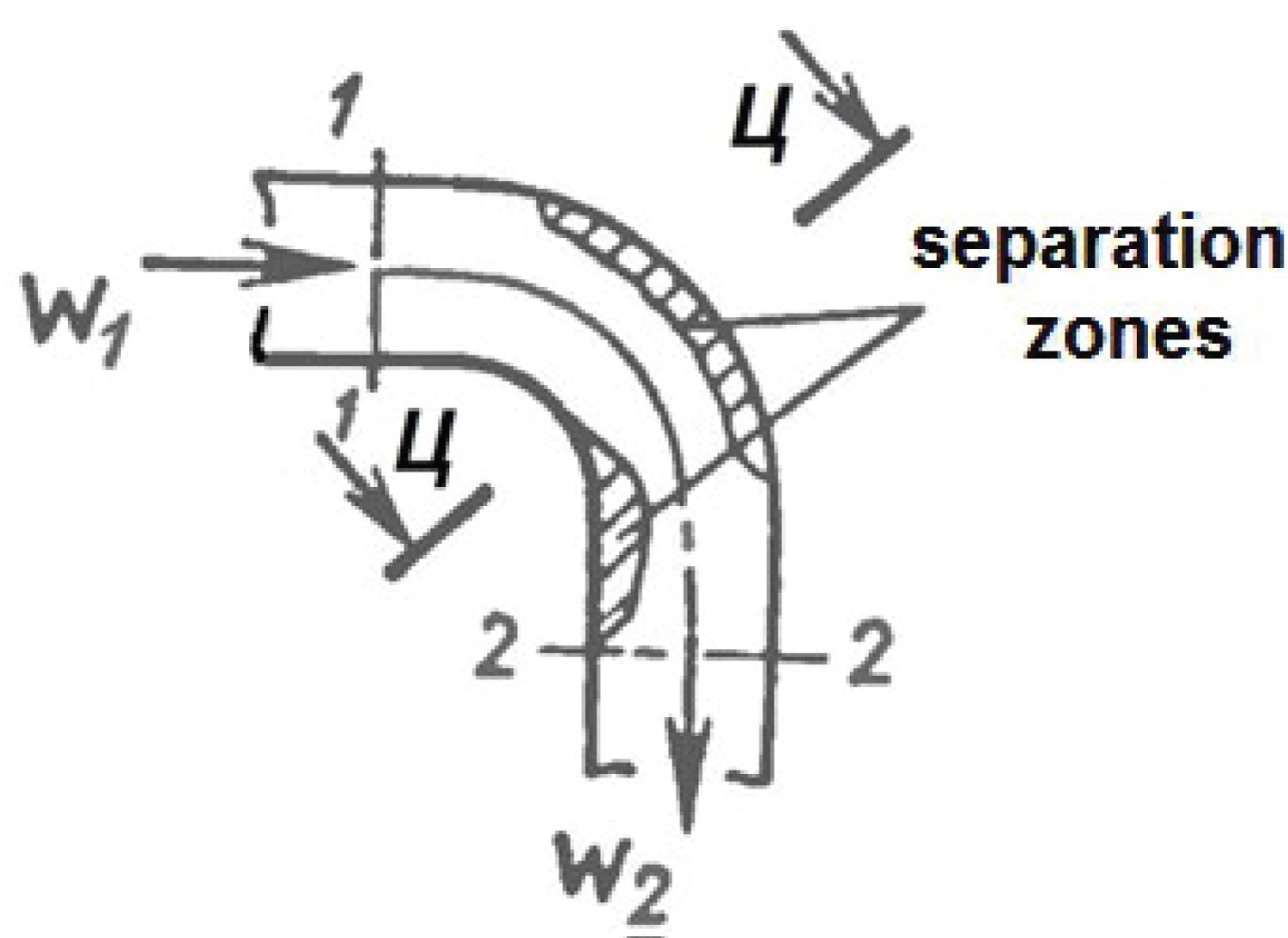
Figure 1: Diagram of the flow of the gaseous....
Diagram of the flow of the gaseous heat carrier in the pipe bend of the heat exchanger.
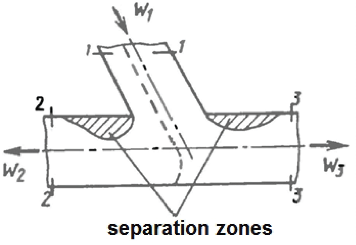
Figure 2: Diagram of the flow of separating.....
Diagram of the flow of separating streams of gaseous coolant in the branching of the heat exchanger pipeline.
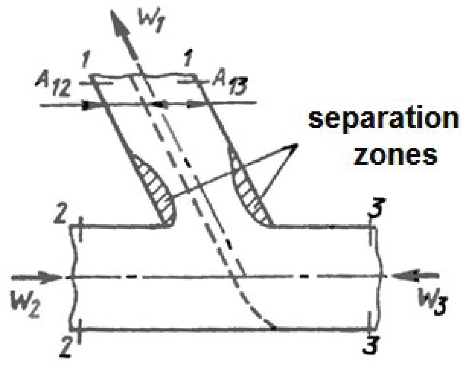
Figure 3: Flow diagram at the confluence of....
Flow diagram at the confluence of the gaseous heat carrier flows in the branching of the heat exchanger pipeline.
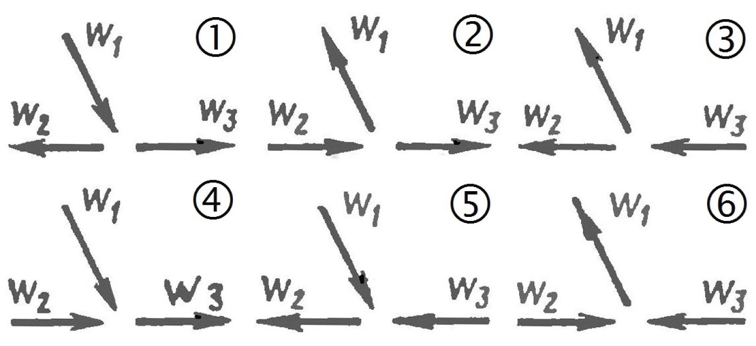
Figure 4: Typical flow patterns of gaseous coolant....
Typical flow patterns of gaseous coolant streams in the branching pipelines of heat exchangers.
References
- Abramovich GN (1976) Applied gas dynamics. Izdatel'stvo Nauka, Russia, 888.
- Loytsyansky LG (1987) Mechanics of liquid and gas. Izdatel'stvo Nauka, Russia, 840.
- Idelchik IE (1983) Aerohydrodynamics of technological devices. (Inlet, outlet and distribution flow by cross section devices). Mashinostroenie, Russia, 351.
- Kruglov MG, Mednov AA (1988) Gas dynamics of combined internal combustion engines. Mashinostroenie, Russia, 360.
- Altshul AD (1982) Hydraulic resistance. Nedra, Russia, 224.
- Idelchik IE (1975) Reference book on hydraulic resistance. Mechanical Engineering, Russia, 427.
- Idelchik IE (1992) Handbook on hydraulic resistance. In: Steinberg MO, Mechanical Engineering, Russia, 672.
- (2001) Reference book on the calculations of hydraulic and ventilation systems. In: Yurieva AS, ANO NPO "Peace and Family", St. Petersburg, Russia, 1154.
- Shevelev FA (1973) Tables for hydraulic calculation of steel, cast iron, asbestos-cement, plastic and glass water pipes. Stroyizdat, Russia, 112.
Author Details
IE Lobanov*
Doctor of Technical Sciences, Moscow Aviation Institute, National Research University, Russia
Corresponding author
IE Lobanov, Doctor of Technical Sciences, Moscow Aviation Institute, National Research University, Moscow, Russia.
Accepted: May 13, 2021 | Published Online: May 15, 2021
Citation: Lobanov IE (2021) Analytical Solution of the Stationary Subcritical Flow of a Gaseous Coolant in the Branches of the Heat Exchange Pipelines of the Apparatus. Int J Healthc Syst Eng 3:007.
Copyright: © 2021 IE Lobanov IE. This is an open-access article distributed under the terms of the Creative Commons Attribution License, which permits unrestricted use, distribution, and reproduction in any medium, provided the original author and source are credited.
Annotation
In the study, analytical solutions were obtained for the problem of determining the flow parameters in the branching of the gaseous coolant flows in the pipelines of heat exchangers. Earlier it was stated that only numerical solutions of this problem can take place. The work substantiated the choice of a theoretical model for mathematical modeling of the flow of a gaseous coolant in the branches of pipelines of heat exchangers with an acceptable degree of approximation to the real flow and the complexity of the necessary calculations - a thermodynamic model of a subcritical stationary flow of a compressible gas. Analytical solutions of the problem of flow in the branching flows of a gaseous coolant in pipelines of heat exchangers were obtained, while earlier there were only numerical solutions of this problem.
Keywords
Theoretical, Analytical, Flow, Coolant, Gas, Stationary, Subcritical, Pipeline, Branching, Heat exchanger
Introduction
The necessity of application of mathematical models of flows of a gaseous heat carrier in branches of pipelines of heat exchangers
The choice of a certain physical, and in the future also a mathematical model, depends on the goals of not only mathematical modeling, but also physical modeling, the construction of various techniques and the processing of experimental data.
The choice of the model for the flow of the gaseous coolant in the pipeline of the heat exchanger and the corresponding fulfillment of the equality of similarity criteria for physical modeling is due to the degree of complexity of the installation design, and the choice of the model for the calculation method is determined by the permissible degree of proximity to the real flow and the complexity of the necessary calculations.
In some models, thermodynamic models of a gaseous coolant are also used - models in which the change in parameters in a certain space and time is not taken into account.
Within the framework of this study, the flow of a gaseous coolant in the branches of pipelines of heat exchangers is considered as subcritical and stationary.
The actual stationary flow of a gaseous coolant in pipelines of heat exchangers is not one-dimensional and is accompanied by losses of mechanical energy, therefore, in the calculations, a flow coefficient μ is used, which is less than unity, with which it is possible to take into account the narrowing of the flow and the loss of mechanical energy. Depending on the ratio of pressures and flow areas, the flow coefficient μ can be determined from the data of experimental static blowdowns.
The flow coefficient μ is determined as the ratio of the actual flow rate at the inlet to the pipeline of the gaseous coolant G1 to the theoretical G'1, i.e. with flow without losses [1,2]. In works [1-4] it is shown that the lower value of the flow rate G1 in comparison with the flow rate G'1 is due to the fact that the density ρ'1 and the velocity W'1 at the pipeline inlet are greater than the corresponding actual values of density and velocity ρ1 and W1.
A two-dimensional non-stationary model of an ideal r can be used Basis for the computational study of the structure of the gas flow in the branching of pipelines of heat exchangers.
The calculated values of the parameters of the gaseous coolant obtained using this model can approximately correspond to the parameters of the real flow of the gaseous coolant, since due to the assumption of the constancy of the parameters along the third coordinate, it is impossible to determine the actual sizes of the separation zones and the distribution of the parameters of the gaseous coolant of the real three-dimensional flow [1-3]. The above mathematical models make it possible to assess the qualitative regularities of changes in the structure of flows and the distribution of parameters of the gaseous coolant in the pipelines of heat exchangers, depending on the design parameters of the branches.
Determination of the parameters of the gaseous coolant in the boundary sections of the branching of heat exchangers, it is also necessary to set the boundary conditions when calculating the flow of the coolant in the straight sections of the pipelines of the heat exchangers.
When a gaseous coolant flows in the pipelines of heat exchangers, the loss coefficient ζ can be used to take into account losses, which expresses the energy losses lП as a certain fraction of the kinetic energy of a stationary flow of a gaseous coolant (for the energy equation for a one-dimensional steady flow of a gaseous coolant, l is defined as the work L referred to unit time and unit mass of gas, namely: l = L/(G•dt), i.e., as energy equivalent to the power of unit mass of gas) [1,2,4]:
The loss coefficient ζ during the flow of a gaseous heat carrier in the pipeline of a heat exchanger can be defined as, for example, in the flow of a heat carrier, which is considered as an incompressible gas, in an elbow (Figure 1). In sections 1-1 and 2-2, it is assumed that the velocity profiles are slightly different from the ideal uniform profile. Let us write the Bernoulli equation for such a flow of a gaseous coolant (p0 is the pressure of the inhibited flow or total pressure) [1,2,4]:
In the left and right parts, the first two terms are the pressures of the stagnant flow; therefore, the loss coefficient ζ for an incompressible gaseous coolant will express the relative fraction of the total pressure loss:
Therefore, it is necessary to determine, for example, from experimental data, the total pressure loss and
The total pressures can be determined, for example, experimentally, using a total pressure receiver. The speed W2 is calculated if the flow rate of the gaseous heat carrier is known, for example, experimentally, according to the relation G = ρW2A2 (A is the cross-sectional area of the heat exchanger pipeline).
For an incompressible gaseous heat carrier of the heat exchanger, the change in the flow rate in the section 2-2 is determined by a change in the cross-sectional area of A1 and A2, since with a constant gas density from the continuity equation - ρ1W1A1 = ρ2W2A2 - the equality W2 = W1•(A1/A2) follows. Therefore, the loss factor also expresses the relative proportion of the static pressure loss. Resistance coefficient dependence ζ can be obtained by comparing the Bernoulli equation for a gaseous coolant flow without losses with a similar Bernoulli equation for a flow with losses ((p2) id is the static pressure in section 2-2 for a lossless flow) [1,2,4]:
The gas flow in the pipe bends of heat exchangers is a non-uniform flow with a complex spatial structure, which depends on the characteristics of the flowing gaseous coolant and the geometry of the channel. FROM The silts of inertia tend to maintain the initial straight-line motion, so the pressure on the outer wall of the channel increases, and on the inner wall it decreases. The velocity of gas particles located in the boundary layer in the direction of the main motion is relatively small; therefore, the pressure gradient formed in the cross section leads to the movement of these particles along the channel perimeter from the outer wall to the inner wall and the formation of a reverse compensating motion in the core, as a result of which in the cross section secondary motion is formed in the form of a paired vortex.
The speed of the main flow of the gaseous coolant in the pipe bend The gadfly of the heat exchanger will change inversely to the change in pressure: the velocity of the gaseous coolant, in comparison with the velocity in section 1-1, decreases outside the boundary layer of the outer wall and increases outside the boundary layer of the inner wall. If the curvature of the heat exchanger pipe bend is small, then the pressure in the boundary layer can be practically equal to the pressure of the stagnant flow, and a vortex zone can be formed along this wall. After passing the central section Ts - Ts, a redistribution of the velocity and pressure profile takes place in such a way that the pressure decreases from the inner wall to the outer wall, and the velocity increases [1,2,4-8].
The total energy losses of the gaseous coolant flow in the pipe bend of the heat exchanger can be divided into friction losses, internal Travel and output losses associated with the unevenness of the velocity field and their subsequent leveling. Internal losses are determined by the frictional losses of the secondary flow and the losses due to the formation of vortex separation zones. Internal and output losses account for most of the total energy losses.
The degree of unevenness of the velocity field, the size of the separation zones, and the intensity of secondary flows depend on the geometric parameters of the pipe bend of the heat exchanger and the Reynolds number Re. The change in the resistance coefficient ζ in the pipeline of the heat exchanger can be found as a function of the above parameters, for example, according to experimental data [5-9].
Losses also increase when the velocity field of the inflowing flow of the gaseous coolant is nonuniform, since the pressure gradient and the size of the separation zones increase.
The Mach number M during the flow of a gaseous coolant in the pipelines of heat exchangers is small, therefore its effect on the drag coefficient is insignificant.
The equalization of the velocity field occurs over a considerable length of pipelines connected to the elbow. In practice, pipelines of heat exchangers can be short; therefore, to determine the resistance coefficient ζ, it is necessary to perform averaging of the parameters in sections 1-1 and 2-2.
Averaging the parameters of the gaseous coolant in the heat pipeline about the exchanger allows you to go from considering a flow with a spatially non-uniform distribution of parameters to considering a flow with a uniform distribution of parameters over the cross-section of the heat exchanger pipeline - to go from considering a large number of values of the parameters of the actual flow, more specifically: vector or scalar fields of parameters, to a significantly smaller number of parameters of the averaged flow.
To simplify the calculation methods of averaging, various assumptions are used, which are made taking into account the peculiarities of the real flows of the gaseous coolant in the elements of the pipeline of the heat exchanger.
If the flow of the gaseous heat carrier is characterized by insignificant heat exchange with the environment, then the temperature of the stagnant flow T0 can be considered constant at all points of the section of the heat exchanger pipeline.
When determining the loss coefficients in the bends and branches of pipelines of heat exchangers, in most cases, it can be considered constant along their inlet and outlet sections.
The loss factor ζ can be related to the flow parameters, both at the outlet of the heat exchanger pipeline and at the inlet. Energy losses can be determined, for example, as follows (W '2 is the flow rate of the gaseous coolant without losses at the exit from the pipeline) [1,2,4]:
Consequently, when using experimental values for the resistance coefficient ζ for branching pipelines of heat exchangers, special attention should be paid to the form of the expression determining the above coefficient.
In addition, in calculating the parameters of the flow of an incompressible gaseous coolant, taking into account the hydromechanical losses in the pipelines of heat exchangers, it is unlawful to use the equality of the temperatures of the inhibited flow, since the ratio between T01 and T02 is determined by the equation of state.
To determine the loss factor ζ for branching pipelines The gadflies of heat exchangers for a coolant in the form of a compressible gas can be made using the structure of formula (3). The following expression:
establishes a connection between the resistance coefficients ζ and restoration of the total pressure σ (σ = p02/p01)with the flow of gaseous heat carriers in pipelines of heat exchangers. After transformations, we have:
Loss of operability of the compressible gas the coolant in the heat exchanger piping can be estimated using the loss factor ζ comp, if the work is defined as the adiabatic work of compression, which must be spent to restore the total pressure p02 to the initial pressure p01 [1,2,4]:
Thus, for mathematical modeling of the flow of a gaseous coolant in the branches of pipelines of heat exchangers with an admissible degree of approximation to the real flow and the complexity of the necessary calculations, it is possible to reasonably opt for a thermodynamic model of a subcritical steady flow of a compressible gas.
Mathematical Modeling of the Flow Parameters of a Gaseous Coolant in Branches of Pipelines of Heat Exchangers
For an energy-insulated isentropic flow, the thermodynamic parameters of a gaseous coolant are related as follows (γ is the isentrope index) [1,2,4]:
The parameters of the one-dimensional stationary flow at the outlet in section 2-2 (Figure 1) of the gas-dynamic device of the heat exchanger are determined if the parameters at the inlet 1-1 are known at the known value of the total pressure recovery factor σ = p02/p01 (p0 is the stagnant flow pressure or total pressure) are determined from the solution of a system of nonlinear equations:
The last system of equations can be applied to the methodology for calculating the steady flow of a gaseous coolant with a more complex flow structure in triple branches or tees of pipelines of heat exchangers.
The diagram of this flow, more specifically: the separation of the flow, of the gaseous coolant in the pipeline of the heat exchanger with the designations of the parameters in the characteristic sections are shown in Figure 2.
Streamlines, shown by dotted lines, shown in Figure 2 correspond to dividing the flow entering the branch into two flowing out through the branches. For Figure 3 dashed streamlines correspond to dividing streamlines at merging streams.
The gas flow in the branched pipe of the heat exchanger is characterized by a complex spatial structure with an uneven distribution of parameters in the sections 2-2 and 3-3.
It is postulated that the flows of the gaseous heat carrier do not mutually influence each other.... The values of the parameters in the section 1-1 and the recovery coefficients σ1 and σ2 are known; pressures in sections 2-2 and 3-3 are taken to be practically equal.
The assumptions made make it possible to write down a system of nonlinear equations for determining the parameters of the gaseous coolant in the above sections 2-2 and 3-3:
For the considered model of a one-dimensional stationary flow in a branched pipe of a heat exchanger, it is necessary to specify the structure and parameters to be determined before solving the corresponding system of equations. The flow in pipelines of heat exchangers is subcritical; therefore, it is necessary to set the pressure values in sections 2-2 and 3-3 and two parameters in section 1-1. It is this choice of independent parameters of the state of the gaseous coolant in the branching sections that will correspond to the above-established flow patterns.
The parameters of the flow of the gaseous heat carrier within the framework of the one-dimensional model after the merging of the flows, the parameters of the gaseous heat carrier must correspond to the condition of equalizing their values. It is assumed that heat and mass transfer processes do not occur between the gas flows flowing through different areas A12 and A13 (A1 = A12 + A13) in section 1-1 (Figure 3), therefore, they are characterized by different densities and velocities, but equal pressures.
Analytical Solutions to the Problem of the Flow of a Gaseous Coolant in the Branches of Pipelines of Heat Exchangers
The flow of a gaseous heat carrier in the branching of pipelines of heat exchangers accompanied by turbulization and generation of separation zones, which, in turn, causes significant losses of mechanical energy.
Qualitative and quantitative Estimates of losses, as well as the structure of the flow, in stationary flows in the branching of pipelines of heat exchangers are most often established on the basis of experiment.
In the overwhelming majority of cases, parameters for stationary gas flows in pipelines of heat exchangers are investigated, since the main flow regime for these conditions is turbulent stationary.
Additional assumptions when calculating the flow parameters in pipelines of heat exchangers should be considered the invariability of the shape of the channels and the separation or merging of gas flows (Figure 2 and Figure 3).
In this case, a technique is considered for calculating the parameters in the branches in the pipelines of heat exchangers, limiting ourselves to the problem of determining the boundary conditions of the differential problem of unsteady one-dimensional flows in straight sections of pipelines.
The boundary conditions are set as follows. At open boundaries, the number of specified boundary conditions is equal to the number of characteristics departing from the boundary, and the boundary conditions corresponding to the incoming characteristics are determined by solving a differential problem. Therefore, assuming that in the section of the branching of the pipeline of the heat exchanger adjacent to the branch pipe or receiver, the necessary parameters of the gaseous coolant are known, and based on the postulated positions of setting the boundary conditions, it is possible to substantiate the original system of equations for calculating possible cases of the flow of the gaseous coolant in the branch [1,2,4].
For pipelines of heat exchangers, the following cases of separation and merging of streams in a triple branch or tee are possible (Figure 4).
For convenience, the designation of the sections - respectively, Figure 2 and Figure 3. Within the framework of this study, the setting of boundary conditions will be shown in relation to all cases, and analytical solutions will be implemented only for the most important cases of gaseous coolant flows in the branches of heat exchangers.
For separating streams in the pipeline of the heat exchanger (Figure 4.1) in section 3-3 it is necessary to set two boundary conditions, since two characteristics depart from this boundary; in the section 2-2 of the position of the characteristics, it is necessary to set the pressure p2 or the velocity W2 and the temperature T2, since the position of the characteristics is similar to the section 3-3.
The main system of equations for this case of separation or merging of flows in the pipeline of the heat exchanger is the system of equations (13).
Cases of separation of streams in the pipeline of the heat exchanger Figure 4.2 and Figure 4.3 are symmetric, we can restrict ourselves to considering the first case. In section 2-2 it is necessary to set one boundary condition, since only one characteristic departs from it; equality of pressures of outgoing flows: p1 = p3. In section 1-1, the sought parameters are temperature T1 and velocity W2 or pressure p1.
Now let us consider the method of setting the boundary conditions for the confluence of flows in the pipelines of heat exchangers.
Algorithms for calculating the confluence of flows in pipelines of heat exchangers for the cases of Figure 4.4 and Figure 4.5 are similar, so we will consider only the first case. For the case of the confluence of flows in the heat exchanger pipeline Figure 4.5 in section 2-2 it is necessary to set one boundary condition, and in section 3-3 - two. It is assumed that the coolant flows entering through sections 1-1 and 2-2 do not mix, therefore the sought parameters are the areas of sections A31 and A32 (A31 + A32 = A3), which correspond to the gaseous coolant flows flowing through section 3-3.
It is assumed that the temperatures Т31 and Т32 and the velocities W31 and W32 of the outflowing flows are different, and in section 3-3 the pressure is the same, and also р2 = р1.
Taking into account the above assumptions, the initial system of equations for calculating the flow of a gaseous coolant in the pipeline of a heat exchanger at the confluence of flows (Figure 4.6) is obtained from the main system (13):
Pressure R2 known as the boundary condition in section 2-2; the flow rate G1 of the gaseous heat carrier through the section 1-1 is also known.
The unknown parameters are the velocities W2, W31, W 32 and temperatures T31, T 32, as well as the sectional area A31. Thus, we have a system of 6 nonlinear equations with 6 unknowns. This system of equations can be solved analytically, while it was noted earlier that it can only be solved by a numerical method [4]. System (14) has 4 analytical solutions.
The solution of the system gives 4 roots, only one has a physical meaning, which after simplifications has the form:
Further consider an algorithm for calculating the confluence of flows in pipelines of heat exchangers for the cases of Figure 4.6.
For the case of the confluence of flows in the heat exchanger pipeline shown in Figure 4.6, in sections 2-2 and 3-3 only one boundary condition is determined, since The main condition for this case of merging flows is the condition of equality of pressures p2 = p3, which is specified as the boundary conditions.
In this case, one unknown parameter can be set - pressure p2. For section 1-1, unknown parameters are velocities, temperatures, cross-sectional areas: W12, W13, T12, T13, A12, A13, respectively, and (A1 = A12 + A13).
Taking into account the above assumptions, the initial system of equations for calculating the flow of a gaseous coolant in the pipeline of a heat exchanger at the confluence of flows (Figure 4.6) is obtained from the main system (13):
Here we also have a system of 6 linear and nonlinear equations with 6 unknowns. This system of equations can also be solved analytically, while it was previously noted that it can only be solved by a numerical method [4]. System (16) has 4 analytical solutions. The solution of the system gives 4 roots, only one has a physical meaning, which after simplifications has the form:
(17)
Solutions (15) and (17) were verified numerically, as well as using the means of symbolic computer mathematics.
With the corresponding analogous setting of the boundary conditions, the problem of determining the parameters of the gaseous coolant in the bend of the heat exchanger pipeline can be solved analytically much easier than for the tee.
The presented analytical solutions to the specific problem of the merging of gaseous heat transfer media flows in pipelines of heat exchangers justify obtaining similar analytical solutions for flow separation.
Thus, in this study, analytical solutions to the problem of flow in the branching of gaseous coolant flows in pipelines of heat exchangers, while earlier there were only numerical solutions of this problem.
Main Conclusions
1. The work substantiated the choice of a theoretical model for mathematical modeling of the flow of a gaseous coolant in the branches of pipelines of heat exchangers with an acceptable degree of approximation to the real flow and the complexity of the necessary calculations - a thermodynamic model of a subcritical stationary flow of a compressible gas.
2. Analytical solutions of the problem of flow in the branching flows of a gaseous coolant in pipelines of heat exchangers were obtained, while earlier there were only numerical solutions of this problem.