
International Journal of Optic and Photonic Engineering
(ISSN: 2631-5092)
Volume 6, Issue 1
Research Article
DOI: 10.35840/2631-5092/4532

Article Formats
A Cost-Effective Polymer Fiber-Optic Dynamic Rotation Sensor Based on Intensity-Variation
Table of Content
Figures
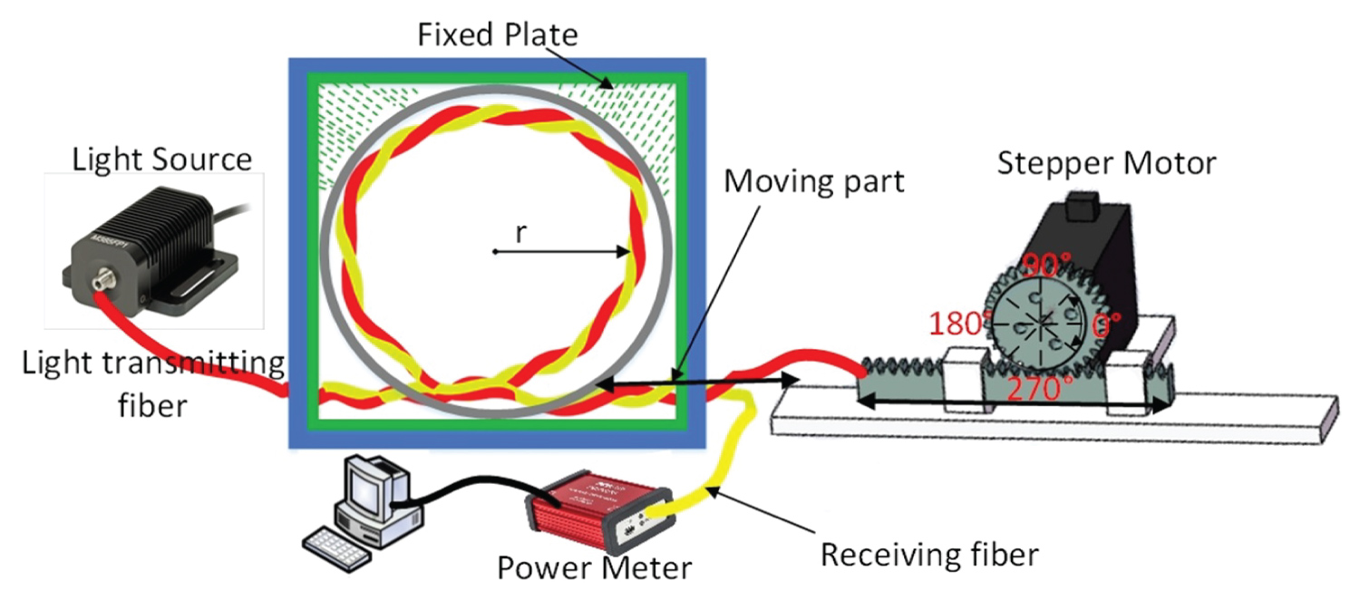
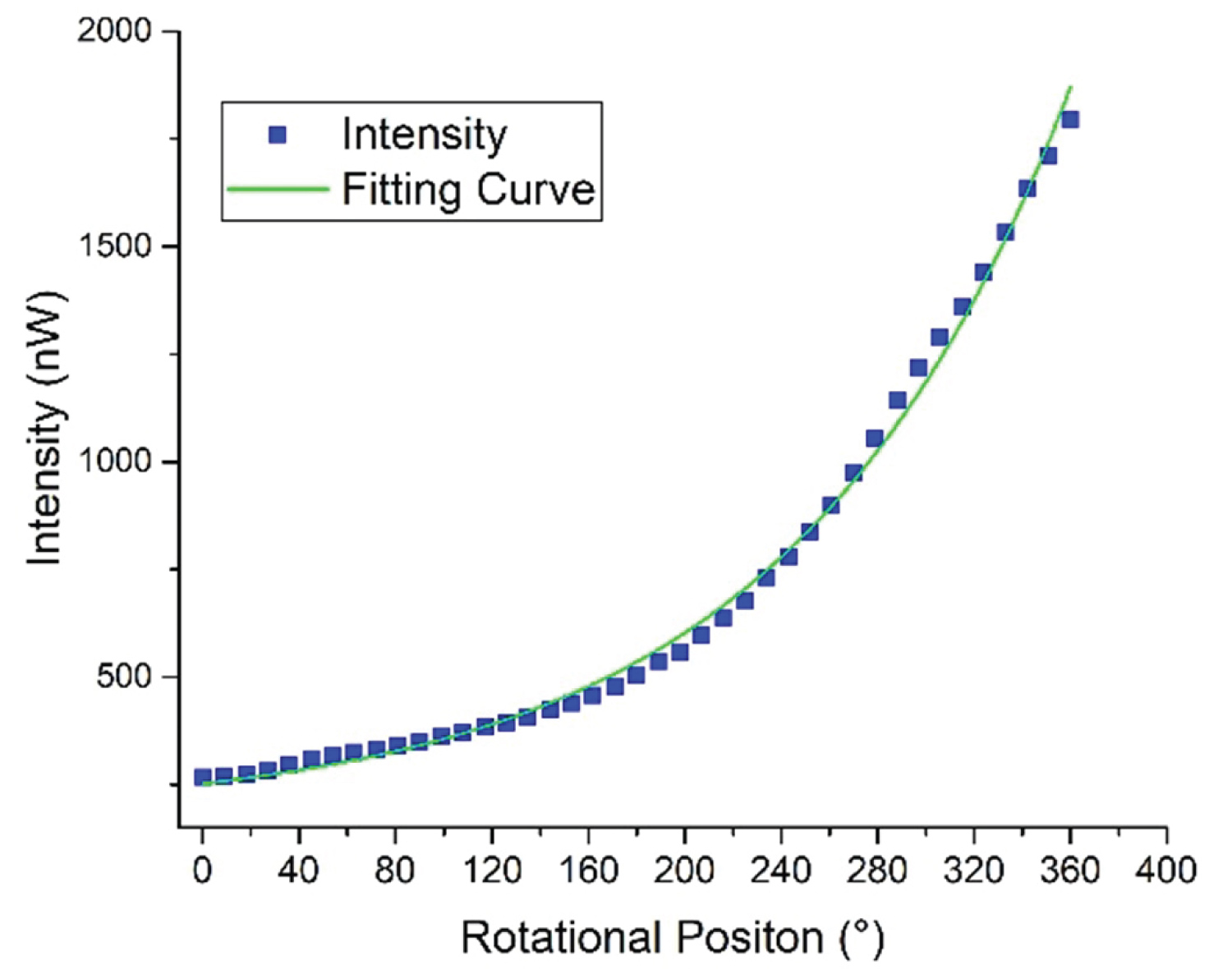
Figure 2: The anti-clockwise measurement.....
The anti-clockwise measurement of the rotational sensor.
References
- Zhong N, Liao Q, Zhu X, Zhao M, Huang Y, et al. (2015) Temperature-independent polymer optical fiber evanescent wave sensor. Scientific Reports 5: 1-10.
- Ghaffar A, Mehdi M, Hussain S, Hussian N, Ali S, et al. (2020) The coupling of scattered-bend loss in POF based the displacement measurement sensor. Sensing and Bio-Sensing Research 29: 100351.
- Ghaffar A, Hou Y-L, Liu W-Y, Dharejo FA, Zhang H-X, et al. (2019) Two-dimensional displacement optical fiber sensor based on macro-bending effect. Optics & Laser Technology 120: 105688.
- Hou Y-L, Liu W-Y, Su S, Zhang H-X, Zhang J-W, et al. (2014) Polymer optical fiber twisted macro-bend coupling system for liquid level detection. Opt Express 22: 23231-23241.
- Yuan W, Khan L, Webb DJ, Kalli K, Rasmussen HK, et al. (2011) Humidity insensitive TOPAS polymer fiber Bragg grating sensor. Opt Express 19: 19731-19739.
- Jiang S (2018) Research on the strain transfer mechanism of FBG radian strain sensor. Int J Opt Photonic Eng 3: 013.
- Ghaffar A, Liu W-Y, An G, Hou Y, Deeba F, et al. (2019) A simple and cost-effective optical fiber angle measurement sensor using polymer optical fiber based on the TMBC. Optical Fiber Technology 53: 102066.
- Ma Z, Chen X (2018) Fiber Bragg gratings sensors for aircraft wing shape measurement: Recent applications and technical analysis. Sensors (Basel) 19: 55.
- Bajića JS, Stupar DZ, Dakić BM, Živanov MB, Nagy LF (2014) An absolute rotary position sensor based on cylindrical coordinate color space transformation. Sensors and Actuators A: Physical 213: 27-34.
- Mohanraj Raja V (2011) Vision based landing for unmanned aerial vehicle. Aerospace Conference, IEEE, USA.
- Guangjun Z, Zhen L, Zhenzhong W, Hong L, Jie J (2010) Four-channel synchronous dynamic measurement system for rudder angles based on line structured light. Chinese Journal of Scientific Instrument 8.
- Zhang Z, Gao G, Jiang X, Hu Q (2011) Research on angle dynamic measurement system for naval gun level platform. International Conference on Electronics, Communications and Control (ICECC), IEEE, China.
- Lee J-J, Ho H-N, Lee J-H (2012) A vision-based dynamic rotational angle measurement system for large civil structures. Sensors (Basel) 12: 7326-7336.
- Billingsley J, Ellin A, Dolsak G (2008) The design and application of rotary encoders. Sensor Review.
- Ehsani M, Husain I, Kulkarni AB (1992) Elimination of discrete position sensor and current sensor in switched reluctance motor drives. IEEE Transactions on Industry Applications 28: 128-135.
- Ehsani M, Husain I, Mahajan S, Ramani KR (1994) New modulation encoding techniques for indirect rotor position sensing in switched reluctance motors. IEEE Transactions on Industry Applications 30: 85-91.
- Leal-Junior AG, Frizera A, Pontes MJ (2018) Sensitive zone parameters and curvature radius evaluation for polymer optical fiber curvature sensors. Optics & Laser Technology 100: 272-281.
- Snyder AW (1972) Coupled-mode theory for optical fibers. JOSA 62: 1267-1277.
- Ghaffar A, Liu W-Y, Yulong H, Zhang H-X, Jia G-W, et al. (2019) Twisted macro-bend coupling based three-dimensional displacement measurement sensor using polymer fiber. OSA Continuum 2: 2773-2782.
Author Details
Jianwei Shi1, Abdul Ghaffar2,3*, Yongwei Li1,4, Qiang Li4, Zhiqiang Li4, Farah Deeba3 and Mujahid Mehdi3
1Department of Automation, Taiyuan Institute of Technology, Taiyuan, China
2State Key Laboratory of Geomechanics and Geotechnical Engineering, Institute of Rock and Soil Mechanics, Chinese Academy of Sciences, Wuhan, China
3University of Chinese Academy of Sciences, Beijing, China
4Science and Technology on Electronic Test & Measurement Laboratory, North University of China, Taiyuan, China
Corresponding author
Abdul Ghaffar, State Key Laboratory of Geomechanics and Geotechnical Engineering, Institute of Rock and Soil Mechanics, Chinese Academy of Sciences, Wuhan, 430071, China; University of Chinese Academy of Sciences, Beijing, 100049, China
Accepted: May 22, 2021 | Published Online: May 24, 2021
Citation: Shi J, Ghaffar A, Li Y, Li Q, Li Z, et al. (2021) A Cost-Effective Polymer Fiber-Optic Dynamic Rotation Sensor Based on Intensity-Variation. Int J Opt Photonic Eng 6:032
Copyright: © 2021 Shi J, et al. This is an open-access article distributed under the terms of the Creative Commons Attribution License, which permits unrestricted use, distribution, and reproduction in any medium, provided the original author and source are credited.
Abstract
The sensor design is quite complicated and robust in the current era, requiring a different signal processing technique to process the data and increase sensor cost. At the same time, demand leads to a simple structure and cost-effectiveness. This paper proposed a rotation sensor using polymethyl methacrylate (PMMA) fiber, and the dynamic has been achieved. The method of design structure is based on the intensity variation. In this structure, two PMMA fibers are taken and twisted. The LED light source is coupled with the first fiber, and light propagates in the second fiber is based on the coupling of macro-bend loss. After twisting, both fibers are kept in a macro-bend shape and fixed on the linear translation stage. The translation stage is drafted via a stepper motor. The macro-bending radius variation causes the macro-bend loss in the first fiber, and the loss is being coupled in the second fiber. The change in the macro-bend radius corresponds to the rotation of the stepper motor. In the experiment, a clock and anti-clockwise cycle are carried out. The 2°\sec, 3°\sec, 5°\sec, and 10°\sec rotational speed are conducted to the sensor's dynamic response. The proposed design is cost-effective and straightforward toward the dynamic rotation sensor.
Keywords
Rotation sensor, Optical-fiber sensor, Polymer optical fiber
Introduction
In the commercial industry, users demand technology integration, cover the product lifetime, maintain and simplify the operation, and combine to ensure integrity and security. Despite that, furniture technology must also be adapted to quantitative, cost-effective, and decisive and control. For illustration, to detect the measurement of shaft movement (such as those found at the steering wheel corners of automatic, aero-engine, or similar vehicle engines), the shaft's operating characteristics must be known to ensure the safe operation of any shaft system. A few essential operating functions include monitoring lateral shaft offset, shaft speed, and torque. Currently, it is difficult to capture or detect all these features for sensors using non-contact technology. At present, there are many sensors, such as temperature [1], displacement [2,3], liquid [4], humidity [5], strain [6], angle [7], and sensor deformation [8]. The rotation sensor plays a vital role in a wide range of technical solutions and becomes the main research and development object [9]. A rotational sensor's importance has been applied in many applications, such as the precise landing of UAV, control of aircraft flight direction, the launch of weapons, measurement structure of sizeable civil aircraft, and test model of wind tunnel [10-13]. Separate specifications require different expectations, such as some desired repeatability, some required accuracy and precise control of circuit speed, high resolution, or low cycle error [14]. Some rotation sensors are used for precision purposes, such as measurement forms, surface mounting, and plate machining. Also, rotational sensors are commonly used in the automotive industry. In machines with switchable resistors for the pulse excitation phase, optimal control is essential to generate rotor angle information [15].
The rotor position is measured directly by mechanical means, such as a flashlight with a serrated driver or a Hall Effect sensor [16]. However, the above rotational sensor is based on the conventional sensing method. The alternative approach to the developed rotational sensor is based on the fiber-optic. The polymer optical fiber (POF) has unique characteristics among different fibers such as glass optical fiber, photonic crystal fiber, and fiber Bragg grating. The POF is cheap, flexible, and easy to handle and bend. Leal, et al. proposed a curvature sensor using POF [17] and achieved rotation up to 45°. However, there is an anxiety of fiber breakage in this method, and the dynamic response has not been conducted. Achieve active rotational sensors using fiber-optics is still a quite challenging task.
Here, we propose a simple, low-cost, and easy build method for dynamic rotation measurement sensors. Along with the power meter, light source, and POF pair, the stepper motor was also used in this design structure. The stepper motor pulls the twisted fibers. As the stepper motor moved twisted fiber, a macroscopic bend loss occurred in transmitting fiber, and couples in the second fiber the coupling power corresponding to different angle positions. The structure of the designed sensor is in the following sections.
Rotation Sensor Structure
The dynamic rotation sensor design set-up includes the polymethyl methacrylate (PMMA) fiber, a light source, the power meter, and a stepper-motor. Stepper motors for operating the system at various rotational positions. The schematic diagram of the structure is shown in Figure 1.
In the arrangement, the light source is LED, having a wavelength of 660 nm, and the power was set at about 10 mW. One light source is coupled with the first POF. In contrast, the second POF is not connected with any laminate source, and the light propagating in the second optical fiber is based on the distorted macro bending coupling phenomenon. The loss formed from the luminance fiber is coupled in the second fiber and detected through the power meter (PM100USB, Thorlabs). The power meter has a resolution of 1 nW. The coupled macro-bend loss power in the second fiber can be calculated by equation 1 [18].
Where C is the coupling coefficient between two fibers, Pc is the power of coupled macro-bend loss is second fiber, and C subsequent as [19];
Whereas V represents to the dimensionless frequency, n1 and n2 are core-cladding refractive index, k is propagation constant, the is the core radius. The POF has a large core diameter, and in the coupled-mode theory, the diameter is essential, which can represent as d is the distance between two fibers. The other important factor is the coupling length, and this is given by equation 5:
As the coupling of power increase by increasing the length of twisting of two fiber. In equation 5, 1 is the twisting length of two fibers. In Tapper and fuse technology, the ratio of coupling power is estimated to constant during manufacture. If there is any disturbance in the coupling region, the coupling power can be changed. Although the trouble is forbidden in the coupling mode theory's proposed method, the disruption is imposed on the coupling part. When the incident light propagates along the bending portion of the fiber, some refraction and tunnel light will be produced because the incident light's angle exceeds the critical angle. In this case, some light will be refracted from the first fiber and coupled in adjacent fibers. For equation 2, the coupling coefficient between the two fibers can be determined. The coupling is measured by a power meter in the second stage and calibrated for different rotational positions.
Experimental Work & Results
Figure 1 shows the experimental setup of the design structure. The fibers used in the test are composed of poly-methyl methacrylate resin and fluorinated polymer, with core and cladding diameters of 980 μm and 1 mm. Besides, the RI of the core is 1.49. Because the core diameter is large and the cladding area is small, it is advantageous to produce noticeable bending loss and tight side coupling. The movement of the twisted macro-bend is performed through pulling using the stepper motor.
The experiment platform was also developed for a different rotational position. The experimental platform's configuration contains a stepper motor (MF60), display unit, driver unit (kh-01), translation table, fixed plate, and a moving plate. The resolution of the stepper motor was 1.8°. Rotate one full turn from 0° to 360° and move the translation stage from 0 mm to 100 mm. Next, place the moving plate on the translation stage and fix the twisted fiber's one-end on the moving plate. One end of the twisted macro-bend was set on the fixing plate, while the other end is movable concerning the moving plate's movement pulled by the stepping motor.
In each case, design experiments are carried out at different rotations, and clockwise and counter-clockwise rotational positions were measured. When the rotation changes gradually, the translation stage begins to start. Therefore, the twisted fiber's bending radius gradually changes, so the influence on the twisting bending radius becomes reduced. The variation occurs in the macro-bending loss concerning the bending radius that begins to increase. The loss of lighting fibers radiates in the environment. A specific amount of lost power is coupled in the neighboring fiber. The lost power efficiently correlates in the second fiber as the second fiber (SK-40) has a large core diameter. In the counter-clockwise direction, the angle varies from 0° to 360°, and the bending radius decreases. In the clockwise rotation, the bending radius increases, and the cycle differs from 360° to 0°.
In diverse periods, both the clock and counter-clockwise rotation were running, and the coupling power was measured by the power meter. The achieved results are shown in Figure 2. The step-change is 9°, and a single rotation measures 40 samples.
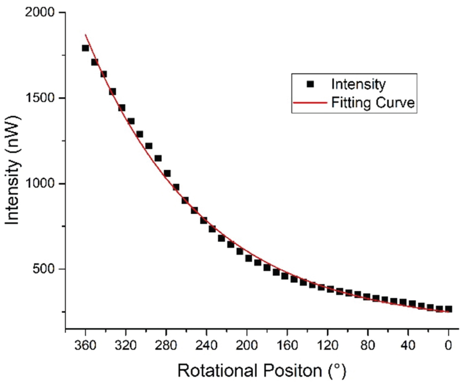
In Figure 3, as the rotation shifts from 0°-360°, the curve begins to rise due to the increase of coupling power. Throughout the rise of the curve, the bending radius of the twisted fiber decreases. At 360°, the coupling power becomes constant and then rotates in reverse, starting from 360°-0°. The rising curve indicates the increase of coupling power, while the decreasing curve suggests the decrease of coupling power. Since the bend radius is kept to a minimum, the start rotation is counter-clockwise. After 360° change, the bending radius is the largest, and the lighting fiber's radiation power is the largest. At 360°, the coupling power changes clockwise during this period with the decrease of bending radius.
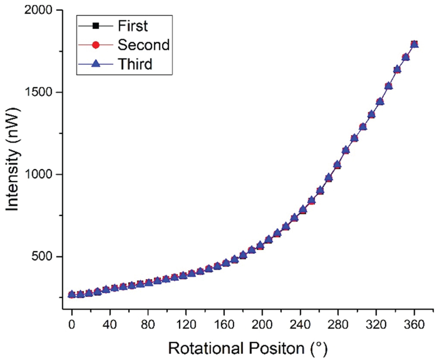
The rotational step change can be changed by applying different input conditions to the drive unit. Thus, in the experimental condition, a smaller step-change also can be achieved, such as 3.6°. The 100 samples were measured in the 3.6° step-change state. The repeatability of the proposed rotational sensor also has been tested. The anti-clockwise rotation was performed for three-time, and obtained data is shown in Figure 4. Each test's measured coupling power has a good consistency, and the R square is about equal to 1.
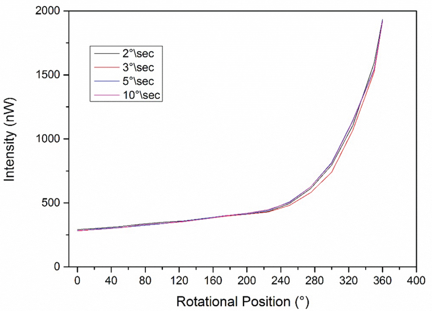
The above results mentioned in Figure 2, Figure 3 and Figure 4 are measured as a static measurement to analyze the coupled intensity. It is found that when the macro-bend radius becomes smaller while the received intensity increases, which causes to decrease in the macro bend radius gradually. After that, the different rotational speed is carried out to obtain the dynamic response of the sensor. The stepper motor is operated through the controller and set as dynamic motion. When the start button is pressed from a controller, the motor starts with constant speed from 0 degrees and stops at 360 degrees. The four different speed is set in a control unit which controls the rpm of the stepper motor. The sensor response is conducted at the 2°\sec, 3°\sec, 5°\sec, and 10°\sec rotational speed. The response is shown in Figure 5. It can be seen from the result that four dynamic motions has been carried out where the sensor has similar output. The received intensity does not change with a dynamic response as compare to static measurement. To the best of our knowledge based on literature, the dynamic rotational sensor based on polymer fiber is proposed for the first time. The proposed rotational sensor has a straightforward and simple design. However, different further tests can also be conducted in the next studies, such as the rotational sensor's multiplexing response, temperature, and humidity effect.
Conclusion
A simple and straightforward polymer fiber-optic rotational sensor is proposed in this work based on the intensity variation method. The sensor structure is consists of a light source, power meter, stepper motor, and two POF. Both fibers were bent after the twisting. The power variation at the detector is associated with a different rotational position. The power variation is caused due to macro-bend loss. The sensor was tested for clockwise rotational, anti-clockwise rotational motion, and dynamic motion in the experiment. The designed sensor is easy to fibrate and easy to handle. In future work, multiple rotational sensors can achieve on a single fiber using the cascading technique.
Acknowledgment
This work was supported in part by the Science and Technology Innovation Project of Colleges and Universities in Shanxi Province under Grant 2020L0627, and in part by the Natural Science Foundation of China under Grant 51705478.
Conflict of Interest
There is no conflict of interest among all authors.