The Architecture of Rotating Machines Condition-Monitoring Using Model-Based System Engineering Approach

International Journal of Signal Processing and Analysis
(ISSN: 2631-5114)
Volume 5, Issue 1
Research Article
DOI: 10.35840/2631-5114/3506

Article Formats
The Architecture of Rotating Machines Condition-Monitoring Using Model-Based System Engineering Approach
Table of Content
Figures

Figure 1: Stakeholders diagram for the electromechanical....
Stakeholders diagram for the electromechanical system monitoring.
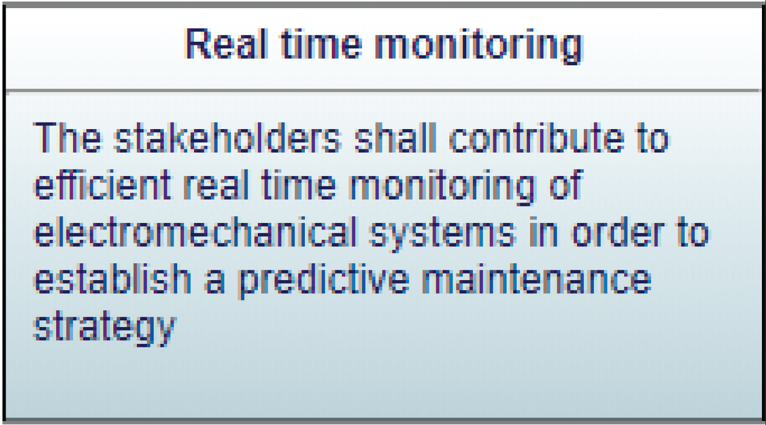
Figure 2: The primary need of the electromechanical.....
The primary need of the electromechanical system monitoring.
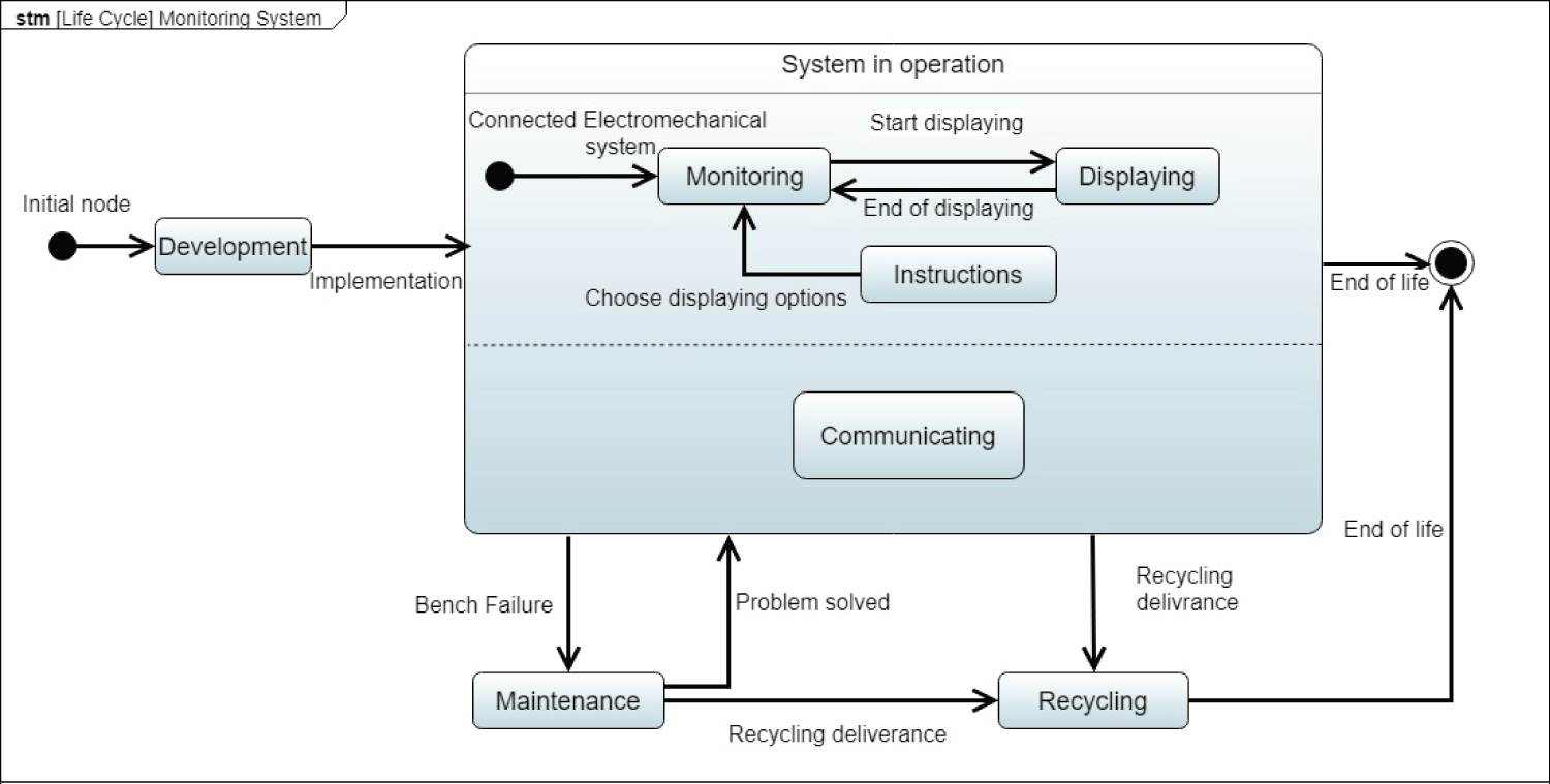
Figure 3: Lifecycle diagram of the electromechanical....
Lifecycle diagram of the electromechanical system monitoring.
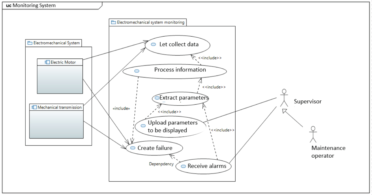
Figure 4: Use case diagram of operational context....
Use case diagram of operational context "System in operation".
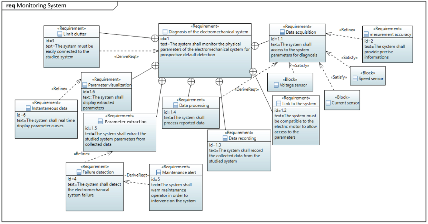
Figure 5: Requirements diagram of the electromechanical....
Requirements diagram of the electromechanical system monitoring.
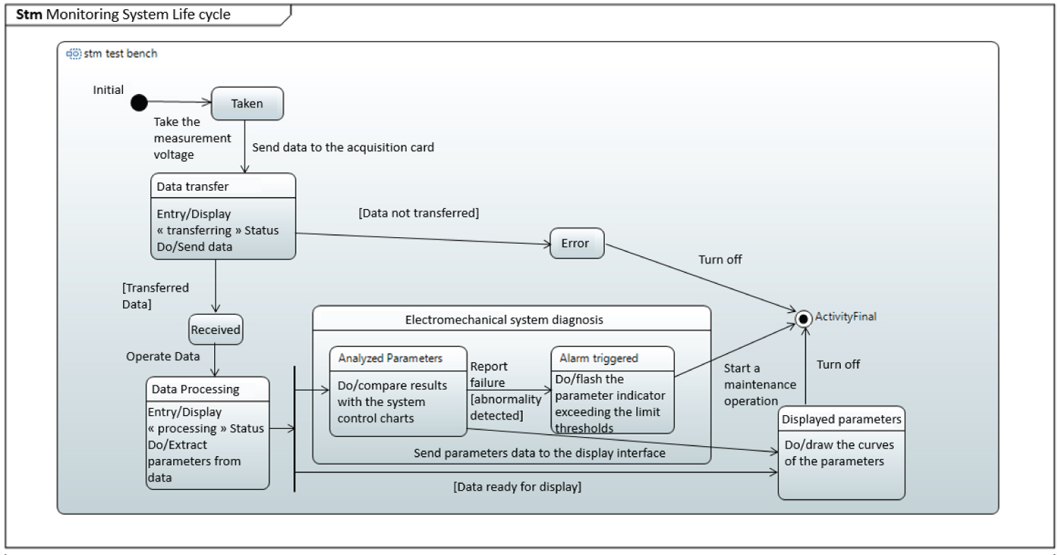
Figure 6: Functional modes diagram of the electromechanical....
Functional modes diagram of the electromechanical system monitoring.

Figure 7: Block definition diagram of the electromechanical...
Block definition diagram of the electromechanical system monitoring.
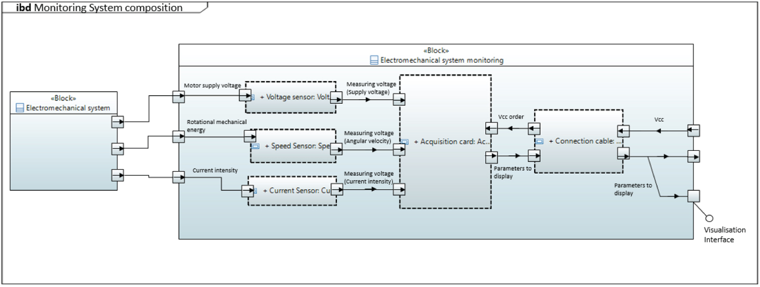
Figure 8: Internal block diagram of the electromechanical...
Internal block diagram of the electromechanical system monitoring.
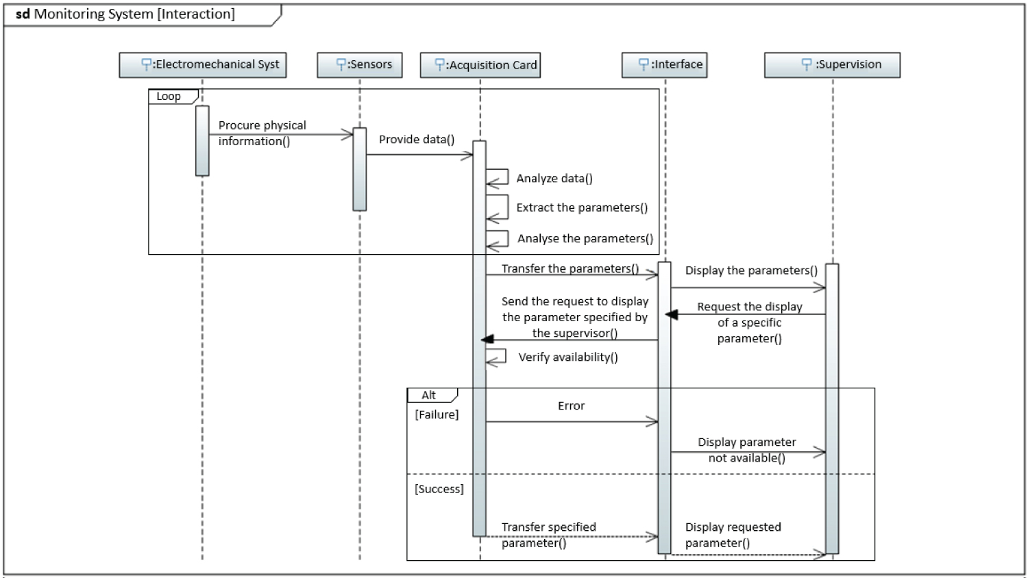
Figure 9: Constructional scenario diagram of the....
Constructional scenario diagram of the electromechanical system monitoring.
References
- AKS Jardine, D Lin, D Banjevic (2006) A review on machinery diagnostics and prognostics implementing condition-based maintenance. Mech Syst Signal Process 20: 1483-1510.
- I Omrane, E Etien, O Bachelier, W Dib (2013) A simplified least squares identification of permanent magnet synchronous motor parameters at standstill. IECON 2013 - 39th Annual Conference of the IEEE Industrial Electronics Society, 2578-2583.
- L Fumagalli, D Elefante, M Macchi, B Iung (2008) Evaluating the role of maintenance maturity in adoption of new ICT in the process industry. IFAC Proc 41: 251-256.
- M Wienker, K Henderson, J Volkerts (2016) The computerized maintenance management system an essential tool for world class maintenance. Procedia Engineering 138: 413-420.
- F Bolaers (2002) Contribution à l'étude et au développement d'un système intégré de suivi de l'endommagement de composants mécaniques sur machines tournantes. Scan R.
- (2015) Condition monitoring and diagnostics of machines - Prognostics- Part 1: General guidelines.
- S Catellani, J Saadi, G Champenoi (1991) Monitoring of a static converter fed machine using average models. In Proceeding of the conference IFAC'91 Safeprocess 24: 467-472.
- D Krob (2017) CESAM: CESAMES systems architecting method a pocket guide. CESAMES Groupe.
- M Edgar Serna, S Oscar Bachiller, A Alexei Serna (2017) Knowledge meaning and management in requirements engineering. Int J Inf Manage 37: 155-161.
- N Benkamoun, W Elmaraghy, AL Huyet, K Kouiss (2014) Architecture framework for manufacturing system design. In Procedia CIRP 17: 88-93.
- I Chalfoun, K Kouiss, N Bouton, P Ray (2014) Specification of a reconfigurable and agile manufacturing system (RAMS). Int J Mech Eng Autom 1: 387-394.
- M Messaadia, AEK Sahraoui, KD Thoben, C Hans (2016) Systems engineering framework to support maintenance systems. 2006 IEEE Int Technol Manag Conf ICE.
- BP Douglass (2016) What is model-based systems engineering? in agile systems engineering. Morgan kaufmann, 1-39.
- C Laing, P David, E Blanco, X Dorel (2020) Questioning integration of verification in model-based systems engineering: An industrial perspective. Comput Ind 114: 103163.
- M Rashid, MW Anwar, AM Khan (2015) Toward the tools selection in model based system engineering for embedded systems - A systematic literature review. J Syst Softw 106: 150-163.
- PH Nguyen, S Ali, T Yue (2017) Model-based security engineering for cyber-physical systems: A systematic mapping study. Inf Softw Technol 83: 116-135.
- J Gardan, N Matta (2017) Enhancing knowledge management into systems engineering through new models in SysML. In Procedia CIRP 60: 169-174.
- JA Estefan (2008) Survey of model-based systems engineering (MBSE). Environment.
- B Cole, V Mittal, S Gillespie, N La, R Wise, et al. (2019) Model-based systems engineering: Application and lessons from a technology maturation project. In Procedia Computer Science 153: 202-209.
- J Murray (2012 ) Model Based Systems Engineering (MBSE) media study.
- JC MARE (2019) Best practices for model-based and simulation-aided engineering of power transmission and motion control systems. Chinese J Aeronaut 32: 186-199.
- G Guillén-Gosálbez, F You, Á Galán-Martín, C Pozo, IE Grossmann (2019) Process systems engineering thinking and tools applied to sustainability problems: Current landscape and future opportunities. Curr Opin Chem Eng 26: 170-179.
- A Sadovykh, W Afzal, D Truscan, P Pierini, H Bruneliere, et al. (2019) On a tool-supported model-based approach for building architectures and roadmaps: The MegaM@Rt2 project experience. Microprocess Microsyst 71: 102848.
- D Inkermann, T Huth, T Vietor, A Grewe, C Knieke, et al. (2019) Model-based requirement engineering to support development of complex systems. Procedia CIRP 84: 239-244.
- K Kübler, S Scheifele, C Scheifele, O Riedel (2018) Model-based systems engineering for machine tools and production systems (Model-Based Production Engineering). Procedia Manuf 24: 216-221.
- M Lukei, B Hassan, R Dumitrescu, T Sigges, V Derksen (2016) Modular inspection equipment design for modular structured mechatronic products - model based systems engineering approach for an integrative product and production system development. Procedia Technol 26: 455-464.
- (2011) Unified Modeling Language. Version 2.4.1, Infrastructure Specification. Object Management Group.
- Object Management Group (2015) "OMG Systems Modeling Language. INCOSE International Symposium 1.4: 346.
- BA Mousavi, R Azzouz, C Heavey, H Ehm (2019) A survey of model-based system engineering methods to analyse complex supply chains: A case study in semiconductor supply chain. IFAC-Papers OnLine 52: 1254-1259.
- J Vidal, F De Lamotte, G Gogniat, P Soulard, JP Diguet (2009) A co-design approach for embedded system modeling and code generation with UML and MARTE. Design Autom and Test in Eur, 226-231.
- J Van Noten, K Gadeyne, M Witters (2017) Model-based systems engineering of discrete production lines using SysML: An experience report. Procedia CIRP 60: 157-162.
- S Zhu, J Tang, JM Gauthier, R Faudou (2019) A formal approach using SysML for capturing functional requirements in avionics domain. Chinese J Aeronaut 32: 2717-2726.
- P Roques (2016) MBSE with the ARCADIA method and the capella tool. 8th European Congress on Embedded Real Time Software and Systems, ERTS 2016.
- A Zolotas, R Wei, S Gerasimou, H Hoyos Rodriguez, DS Kolovos, et al. (2018) Towards automatic generation of UML profile graphical editors for papyrus. Modelling Foundations and Applications, 12-27.
- T Le Sergent, A Le Guennec, S Gerard, Y Tanguy, F Terrier (2011) Using SCADE system for the design and integration of critical systems. SAE Technical Paper.
- M Gallab, H Bouloiz, M Tkiouat (2017) Towards a model for developing an information system as a decision support to risk assessment. Int J Ind Syst Eng 25: 110-129.
- K Sinha, NR Shougarian, OL de weck (2017) Complexity management for engineered systems using system value definition. Complex Systems Design & Management, 155-170.
- F Kherkhachi, Esseddik (2015) Diagnostic du système isolant des machines électriques par identification paramétrique dans un contexte de maintenance prédictive des turbines offshores.
- O Touhami, M Fadei (2007) Faults diagnosis by parameter identification of the squirrel cage induction machine. IEEE Int Electr Mach Drives Conf IEMDC 1: 821-825.
- Y Koubaa (2006) Asynchronous machine parameters estimation using recursive method. Simul Model Pract Theory 14: 1010-1021.
- E Walter, L Pronzato (1997) Identification of parametric models from experimental data. Springer, Masson, London.
- J Gausemeier, T Gaukstern, C Tschirner (2013) Systems engineering management based on a discipline-spanning system model. Procedia Computer Science 16: 303-312.
- DD Walden, GJ Roedler, KJ Forsberg, R Douglas Hamelin, TM Shortell (2015) INCOSE systems engineering handbook. John Wiley and Sons, USA, No. 4.
- S Sekkat, K Kouiss, J Saadi, L Deshayes (2013) Developing integrated performance measurement system using component based approach. Int J Comput Commun Control 8: 294-303.
- CJ White, BL Mesmer (2019) Research needs in systems engineering: Report from a University of Alabama in Huntsville workshop. Syst Eng, 1-11.
- Q Do, S Cook, M Lay (2014) An investigation of MBSE practices across the contractual boundary. Procedia Comput Sci 28: 692-701.
- M Russell (2012) Using MBSE to enhance system design decision making. Procedia Comput Sci 8: 188-193.
Author Details
Mariya Guerroum1*, Mourad Zegrari1, Abdelhafid Ait Elmahjoub1, Ali El Alaoui2, Janah Saadi2 and Laurent Deshayes3
1Laboratoire Ingénierie des structures, Systèmes Intelligents et Energie Electrique (LISSIEE), ENSAM Casablanca, Hassan II University, Morocco
2Ecole Nationale Supérieure d'Electricité et de Mécanique ENSEM, Hassan II University, Morocco
3Innovation Lab for Operations, Mohammed VI Polytechnic University, Morocco
Corresponding author
Mariya Guerroum, Laboratoire Ingénierie des structures, Systèmes Intelligents et Energie Electrique (LISSIEE), ENSAM Casablanca, Hassan II University, Casablanca, Morocco.
Accepted: October 12, 2020 | Published Online: October 14, 2020
Citation: Guerroum M, Zegrari M, Elmahjoub AA, El Alaoui A, Saadi J, et al. (2020) The Architecture of Rotating Machines Condition-Monitoring Using Model-Based System Engineering Approach. Int J Signal Process Anal 5:006
Copyright: © 2020 Guerroum M, et al. This is an open-access article distributed under the terms of the Creative Commons Attribution License, which permits unrestricted use, distribution, and reproduction in any medium, provided the original author and source are credited.
Abstract
Digital technologies have the potential to achieve a breakthrough in productivity performance affecting the whole supply chain in the mining industry. The productivity cannot improve without enhancing automation and maintenance activities and its management in factories. Enterprise Asset Management system is one of the Information and Communication Technologies tools. As related to maintenance management, asset management ensures a vast difference across strategies in terms of efficiency and adaptation on value creation and capture. Such a program should be alimented by a condition-monitoring system. The aim is to optimize material and equipment flow and improve anticipation of failure. This paper presents a Model-based System Engineering architecture of rotating machines condition-monitoring. We reviewed MBSE approaches and applications to investigate the convenient technic to adopt. The designed system can collect data and identify rotating machine physical parameters. These pre-steps are an input serving the predictive maintenance strategy design. Then Operational, functional and constructional visions of the system are presented via SysML diagrams building a more comprehensive understanding of the detailed layout plan. Finally, we state that the MBSE technic is yet to be explored for Maintenance systems development.
Keywords
Model-based systems engineering, Enterprise architecture, Condition-monitoring, Predictive maintenance, Maintenance management, Enterprise asset management systems, System modeling language
Introduction and State of the Art
The digital transformation within the mining industry leads to a tide of change in the interaction with stakeholders at every step of the value chain. From mineral exploration, through mining and production, to downstream sales and distribution, digitalization is defining new approaches challenging the traditional business models.
Nowadays, electromechanical devices and electrical machines play an important role in all industrial applications. Ensuring their availability and dependability is a fundamental task. Therefore, the management of maintenance should fit the digital transformation road-mapping.
The change from a situation where "we suffer breakdowns" to a situation where "we control breakdowns" requires a few technological means as well as technical knowledge of appropriate and powerful analysis. The switch to a proactive reliability-based approach is an important aspect of Condition Based Maintenance (CBM) [1]. The continuous condition-monitoring of the equipment operating through quantifiable and qualifiable data and its interpretation thus makes it possible to prevent a malfunction before it happens and to eliminate false alarms that can slow down production by managing the equipment in the best way possible [2].
The maintenance constitutes a substantial part of the Manufacturing Execution System (MES). The innovation in the predictive maintenance field involves also the activities enabled by Information and Communication Technology (ICT) and that is where a well-implemented Computer Maintenance Management System (CMMS) and/or Enterprise Asset Management (EAM) system is one of the key tools that are essential to underpin proactive maintenance management. The trend is to move the Maintenance towards the Asset Management paradigm, involving important issues about asset life cycle cost and availability of the asset, that can be easily translated in gained production, above all when considering the process industry (24h of working time) [3]. For example, the adoption of a modern CMMS that can be easily connected to all other running company's systems as ERPs is the first and most significant step that organizations can undertake to follow the pathway leading to industry 4.0. [4].
It is, therefore, necessary to develop systems for detecting (monitoring) and evaluating (diagnosis) the state of these. To manage and develop an integrated complex system, we need to use a tool that enables responding to this devices [1,5-7] requirement. System Architecting & modeling Approaches have attracted the attention of several research teams in various fields such as aeronautical industry and automotive [8]. It is indeed much easier to deform an existing system architecture to adapt it to a series of new needs, rather than constructing it from scratch. System Engineering Approach is also used in Software development [9] and manufacturing Systems [10], to determine specifications for reconfiguration [11] and to define a new complex system [12].
Complex systems are known to be hard to design due to the required multidisciplinary knowledge. Model-based Systems Engineering (MBSE) is a way to improve classical systems design challenging document-based approaches while considering a complex system architecting. Douglass has provided the importance of MBSE as one is dealing with systems instead of a discipline-specific engineering problem, reviewing workflow models (V-Model, Incremental Model, and Hybrid V-Model) [13]. MBSE is a powerful approach to adopt ensuring features, such as consistency, traceability, analysis, verification, and validation [14]. Many research works have been lead to review MBSE approaches, to prove its flexibility and to emphasize the interest of selecting this methodology [8,15-19]. Murray has spanned some of MBSE advantages: improving communication, managing the system's complexity at any level, enhancing quality, managing Knowledge and transferring learning fundamentals about Systems Engineering [20].
Research studies have stated that modeling activity is the core of MBSE. Many Frameworks and technological solutions were created to meet a certain need or specification according to the field of application. Mare listed best practices for modeling of aircraft systems after reviewing technical standardization documents [21]. Chemical process systems Engineering methodologies, algorithms, and tools are paraded by Guillén-Gosálbez, et al. focusing on sustainability on different scales [22]. Sadovykh, et al. introduced the project MegaM@Rt2, an integrated framework incorporating methods and tools for continuous system engineering and runtime verification and validation (V&V) applied to embedded systems [23]. While Do, et al. investigated practices involving MBSE in a contractual scope of tendering environment for a ground-based air missile defense system. They proposed Whole-of-System Analytical Framework (WSAF). This framework adopting the learn-by-doing research approach features MBSE models of the system through the transition from acquirer capability definition and supplier proposition while tendering, till their use and maintenance. Inkermann, et al. developed a concept for model-based requirements engineering in Automotive complex system development at the early stages of the design process [24]. Whereas Kübler, et al. proposed a combination of Model-Based methods, called Model-Based Production Engineering MBPE approach, adapted to the production system as a collection of sub-systems from different points of view during its lifecycle [25]. In the same topic, Lukei, et al. applied MBSE to figure out a design methodology for modular mechatronics products production systems for the development and the quality inspection while specifying the interoperability of functions [26].
Modeling languages for MBSE approaches are mainly Unified Modeling Language (UML), Systems Modeling Language (SysML) and Modeling and Analysis of Real-Time and Embedded systems (MARTE) [27]. UML is a graphical modeling language designed by Object Management Group (OMG) to provide a standardized method for system analysis, design, and implementation. It is dedicated to software development and object-oriented design. SysML is an extension of UML specialized in Systems Engineering allowing specification, analysis, conception and V&V [28]. This Object-oriented modeling language is flexible and modularly structured hence the user can use it effectively without knowing the integrality of language units [29]. It allocates accurate descriptions across views of the modeling process. In our study case, we focused on UML/SysML diagrams as OMG's MARTE is dedicated to embedded and electronic applications, as a modeling platform [30]. In point of fact, Van Noten, et al. presented SysML as being the standard formal graphical modeling language for MBSE [31]. In the avionics domain, ZHU, et al. have proposed the MBSE Approach using SysML to define functional requirements tested on the Onboard Maintenance System [32]. There are several tools used for this purpose like Capella based on ARChitecture Analysis and Design Integrated Approach (ARCADIA) explained by Roques [33], and Papyrus [34] driven by automated model-to-model and model-to-text transformations. Modelio is also a platform for UML/SysML [23]. Several research works have reviewed the different modeling tools based on UML/SysML like [15,20]. SysMl has proven that it is a flexible Modeling language for MBSE, and models are is still to be developed to fit different requirements according to the system nature [17,35].
CESAMES's MBSE Framework [8] is a step by step approach to formalize conceptual design and organic architecture to produce complex systems. Maintenance systems are qualified as complex systems due to all components managed like maintenance activities, assets, humans, data, and risks [36]. Therefore, it is interesting to explore CESAMES's flexible approach to vulgarize, and then well define, the maintenance system using UML/SysML diagrams. The maintenance program recommends maintenance decisions based on the information collected through condition monitoring. It consists of three main steps: data acquisition, data processing and maintenance decision-making [1]. Diagnostics and prognostics are two important aspects of the predictive maintenance strategy, especially when using multiple sensors in condition monitoring. The maintenance management model can also rely on MBSE Framework, and such effect can be either to modify the requirements influencing the design for the product or to improve/change the production system technology or layout concerning machining/assembling operation [37]. We evaluated this approach as a core modeling for integrating predictive maintenance applications.
The purpose of this paper is to design a monitoring system of electromechanical systems based on predictive maintenance by parametric identification. We propose to implement algorithms [2,7,38] on the monitoring system in order to follow the evolution of mechanical and electrical parameters of the machine such as friction, moment of inertia, resistances, and inductances over time. As indicated in the literature these parameters are related to faults or the first stages of defects. For example, an increase in friction may mean a need for lubrication. If this augmentation remains despite lubrication, it means that it is a beginning of wear on the bearing [5,39] that requires maintenance tasks.
The objective of this work is to develop a machine maintenance strategy using the real-time evaluation of the system's physical parameters including the electric motor and mechanical transmissions in the industrial environment [7]. This strategy is based on algorithms simulation [40], collected data by sensors [41], and interfaces & alerts management [42]. This predictive maintenance approach will meet the explicit needs:
- Predict failures;
- Optimize preventive maintenance breakdowns;
- Minimize sudden stops of production;
- Increase the synthetic rate of return;
- Ensure better traceability;
- Improve the organization of traditional maintenance.
To develop the various requirements that fulfill the expressed needs, we have designed our system using the SysML diagrams [17,43,44] to implement an appropriate solution by using the various components (sensors, acquisition card, interface, etc.).
The remainder of this paper is organized as follows: First of all, the main stakeholders are identified, this is the definition of the external systems of the System's reference environment. Their related flows are prominent to induce structuring architectural orientations for the System. Secondly, space and time modeling are required to specify the System behavior in the operational architecture section. Thirdly, we have focused on the functional view of the System to design, which is an abstract perception of the solution without getting into the technical aspects. Finally, the constructional architecture details the components and their configuration, making the architecture representation concrete.
Digital Transformation and Integration Environment
It is very important to define precisely the environment architecture. This step has a role in identifying external stakeholders and equivalently different related needs. It can also be used for monitoring the first systems architecting activities [8]. The evaluated needs constitute a basis for the resulting concrete System. Thus, any mistake or role misevaluation can lead to erroneous needs. As a result, functions and components of the system rely on the quality of the environment identification.
This core initial analysis is represented by the stakeholders' diagram in Figure 1, a fusion of two diagrams: The stakeholder hierarchy diagram and the environment diagram. The first one itemizes the hierarchy of external key stakeholders. The second one pictures the reciprocation between the System and its first level stakeholders.
The stakeholders' diagram shows the abstract relationships between the monitoring system, which is our System to design, and its environment. It describes how the system will be integrated with the other elements of the maintenance operations systems. As indicated in Figure 1, the main external systems (stakeholders) trading with the System are:
• The electromechanical system that must be monitored;
• The Supervisor can be an operator from the control room or the production manager;
• The Maintenance workshop for interventions: the manager ensuring the planning while the operator executes the maintenance operation;
• The Diagnostic system is monitoring and determining the state of the system;
• Asset Management using the Computerized Maintenance Management System (CMMS) or the Enterprise Asset Management System (EAM) for managing internal maintenance operations;
• The Environment conditions: either weather conditions or surrounding equipment effects;
• The Database for the storage of collected data;
• The Power supply for the monitoring system components.
It is mandatory to emphasize that the ICT infrastructure of the organization should be ensured and suitable for the successful integration of the condition-monitoring system.
Interactions of the System to Design
Stakeholders needs development
The operational vision of the monitoring system is expressed by multiple interactions with the first level stakeholders. In our case, these interactions reside in the primary need for real-time monitoring such as formalized in Figure 2.
From the perspective of representing the operational contexts, states, and temporal transitions, the lifecycle diagram is drawn with a manner to express consecutiveness, inclusion, and simultaneity.
Identifying and describing the life cycle of the monitoring System addresses issues of System adaptation or reconfiguration in a changing context (resource availability, retrofit, upgrading, recycling). Thus, the lifecycle diagram, as shown in Figure 3, is represented by a state machine diagram which is a dynamic view of the System. It shows the different successive states and the possible transitions of the dynamic blocks. The dynamics of change is sustained by events.
The System's lifecycle is lunched by the monitoring System design (Initial node). Once connected to the electromechanical system, the monitoring operation leads to displaying the parameters depending on the operator's instructions. The System is perpetually communicating with deferent stakeholders such as the database or the control room. Maintenance and recycling operations are also on the cards.
The monitoring system operational descriptions
The use case diagram (uc) describes with accuracy the missions to be fulfilled associated with the operational context "System in operation" of the monitoring System lifecycle. Each mission of the System is related to a stakeholder. The use case diagram in Figure 4 lists the functions performed by the monitoring system and the interconnected stakeholders. The System interacts with the electromechanical system to diagnose when it comes to collecting information or in case of failure detection. Our System communicates with the supervisor through an interface. The maintenance agent is notified when a fault occurs, and initiating maintenance operations is required. The rest of the missions are internal and can be added by the system architect. The purpose is to anticipate some of the monitoring System functions. As said in the previous section, the operational vision is much related to the functional and to the constructional visions. It is very natural to think about modeling the functional context while specifying the interactions between stakeholders and the System to design.
So, the use case diagram gets a preview of two functional missions that the monitoring System affords: Processing the collected data and Extracting parameters.
As a matter of fact, the "extract parameters" mission involves the "processing data" mission. The including relation predicates that the basic use case "requires that" or "cannot be done without" collecting data mission. Regarding the "receive alarms" mission, it is depending on creating failure on the electromechanical system.
The monitoring system must be able to detect such variation in the parameter and recognize that something unusual is happening.
The Monitoring System Functional View
The functional architecture is the key to track down specific and transversal behaviors. This step is ultimate to spot and to manage the emergent behaviors of an integrated System. We must stress that although the functional description of the monitoring System allows thinking about the constructional options, it does not interfere with the technical design choices mechanism. This functional view will serve for comparison and evaluation of the composition architecture [37]. This step gives the functional guide of the System, in other words, the list of all objects that are functionally manipulated.
The monitoring system functional requirements
Requirements are commonly used to formalize system prerequisites, resulting in features or conditions that should be satisfied by the System, depending on any priorities associated with the requirements.
The requirements are also used for modeling, for creating associations with use cases, blocks or any type of element of the model, and then establishing traceability between functions.
The functional requirement diagram (req) Figure 5 is a hierarchical exhaustive description of all functional requirements. It is represented by a two-part box. The top is reserved for the « requirement » stereotype which represents a text-,based requirement, and the title. While the bottom includes id and text properties. Requirements hierarchy describes requirements contained in a specification. Common functionalities can be linked via « satisfy », « refine » and « DeriveReqt » relationships. For example, the "Diagnosis of the electromechanical system" requirement includes the "parameter extraction" requirement for more precision. While "failure detection" is refining the previous requirement to which it is connected and is identified as a way of satisfying "maintenance Alert".
The requirement diagram is providing, for one other time, a preview of the composition of the System which will be exposed in detail in the constructional section. Thus the speed sensor, the current sensor, and the voltage sensor are components, inherited from the block definition diagram, satisfying the functional requirement "data acquisition".
The system functional descriptions
At this level, we used the state machine diagram (stm) in Figure 6 to represent the functional modes of the monitoring system and the events that cause transitions between each mode. These diagram models from a functional perspective time and rationally describes in a consolidated and organized way all inputs and all outputs of the functions of the System.
Firstly, the monitoring System must draw current intensity, voltage and rotation speed signals. And then it must send the data to be operated. In the processing phase, the System extracts the identification parameters from the electromechanical system data. The data processing is followed by two actions:
• Diagnosis of the System based on the extracted parameters ;
• The display of parameters.
Precise algorithms [7] compare the extraction results with the correct functioning electromechanical system thresholds.
Two scenarios can take place. The first is to trigger visible alarms to the supervisor. Maintenance operations are started to repair the failures. As for the second, there is a direct switch to the first post-processing action: The display of parameters. The activity then ends.
In fact, by integrating the functional properties in the operational view, it helps for more precise identification of the problem, to develop the appropriate solution.
The Monitoring System Organic Construction
The constructional architecture is meant to describe precisely the different components and their relative interactions of the monitoring system. This concrete vision of the System helps comprehend details of the structure. The goal is to find answers to stakeholders' needs in the most optimized way while integrating industrial and technological constraints.
The system constructional requirement
The block definition diagram (bdd) represents the constructional view of the System. Thus the main block and the hierarchy of the blocks that compose it, whether software or hardware, are specified in this diagram.
In our case, the bdd diagram in Figure 7 illustrates the components of the monitoring system, resulting in an overall view of the modeled system. For example, the speed sensor block is in the composition of the monitoring system block as an indispensable component. The speed sampling is an operation completed by the speed sensor, and the rotation speed is a value reported by this block.
Constructional descriptions
The internal block diagram (ibd) in Figure 8 describes the white box view. It is based on the « bdd » to assemble the blocks that build the monitoring System. The links represent flows, material, energy, and information, exchanged between the constitutional parts of the System while the diagram frame represents the monitoring System. A block can have multiple ports that specify different interaction points.
This diagram describes the circulation of flows between the different blocks inherited from the « bdd » in accordance with what is prescribed in the specifications. The input information (supply voltage and rated current) and output (speed) of the electric motor are collected via high-performance sensors and then sent to the acquisition card. The latter performs processing operations and sends the extracted parameters to visualization and control interface or personal digital assistant (PDA) and Control System.
The sequence diagram (sd), Figure 9, represents the elements involved in the scenario, as well as the message exchanges between the system and actors, or between parts of the System, in a chronological manner, specifying possible time constraints. The reading of such a diagram is from top to bottom.
The scenario begins with the operation of detecting the information (current, voltage, and speed) of the System. Once the mission of the sensors is complete, the data is supply to the acquisition card. Then, the acquisition card analyses the data, extracts, and analyses the identification of physical parameters from the electric motor before being transferred to the interface. The supervisor or operator reads the settings on the interface and can choose a specific parameter to display. Thus the System executes its request.
Case Study General Remarks
Even though MBSE provides a flexible approach to design systems, accidental complexity can be introduced, leaving several MBSE aspects to develop. This area of research is attracting the interest of system architecting society [45]. Besides, giving extra details can lead to hard to manage complexity in the modeling using SysML. Indeed, some functions were hard to illustrate due to the large paradigm of the modeling language. Persistent gaps between available paradigms and the industrial needs are still existing [14,45] especially to support maintenance activities. MBSE in the literature is used the most in embedded systems, software development, automated processes, and discrete manufacturing systems. MBSE for Maintenance systems is yet to be explored. Further works must focus on Maintenance as a very important concern. We qualify a transition from a document-based approach to a Model-based approach as necessary since tasks can be very complex [46]. The complexity of the maintenance system is due to given multidisciplinary skills - mechanical, electrical and software - required to remedy a problem. Therefore, a simple issue can be hard to identify and cause catastrophic repercussions because of the impractical maintenance system documentation making such a system, already complex as it is, appears more complicated and harder to comprehend. MBSE promotes knowledge management for modelers and users of the maintenance system about its behavior and performance. Even if the system architect is an expert in SysML, all diagrams are easy to understand by any member of the complex system engineering teams. The interest is to make the system concretization and handling a practical process through its lifecycle (from creation to destruction passing by maintenance and adjustments) illustrated in Figure 3. We are interested in the identification of the physical parameters of the electromechanical machine. This architecture is created to specify the cyber-physical system in order to match the mathematical modeling of parametrical identification. Furthermore, the monitoring system Architecture incorporates, in the Data acquisition card, algorithms to follow the evolution of the mechanical and electrical parameters of the electromechanical system. This part is yet to be developed following the MBSE approach and explicating the parametrical identification using mathematical models of the system to be monitored. This modeling would help choose the convenient technologies for the system construction. As well as that, this MBSE approach makes tracking changes an easy task for the systems developers and users, through the reference diagrams.
Besides, team communication is an inherent aspect of knowledge management to be enhanced in maintenance activity in a harsh environment like the mining industry [46]. It should be noted that MBSE can enhance decision making if the views are well defined [47].
Conclusion and Perspectives
In our contribution, we presented the conceptual and technical specifications of our electromechanical system monitoring. We pointed out the importance of the MBSE to design and develop a system for predictive maintenance integration. Predictive maintenance is a technic enhancing maintenance strategies. A reliable condition monitoring system can provide accurate data considered as input of prognostic systems. Therefore, this work is a contribution to help define all requirements and architecture of such a system, by explaining the design process with a specific study case. We have introduced a basic concept for predictive maintenance based on parametric identification, the design of our monitoring System using SysML. We have also noted the relevance of using this method in this field of application not yet explored by the Systems Engineering community.
The precision as a highly demanded aspect in the maintenance policies nowadays. As predictive maintenance is the key to develop durability, security and resources management in businesses, it is very interesting to follow advanced approaches while designing systems in the Industry 4.0 environment. MBSE application on maintenance activities a field to be yet explored.
Our future work will focus on considering the system requirements and behaviors from other stakeholders' points of view while trying to reconcile the aspects of modeling and the need to develop a flexible monitoring system. We also intend to publish our work on the electromechanical system physical parameters' identification algorithm we developed. Then we are intending to propose a framework to enhance the MBSE state of the art for maintenance systems. We are aiming to expand our work to design the prediction maintenance system and to integrate it into the control system in the mining industry context.