
International Journal of Astronautics and Aeronautical Engineering
(ISSN: 2631-5009)
Volume 5, Issue 1
Original Article
DOI: 10.35840/2631-5009/7531

Article Formats
Performance of Fibre-Reinforced Polymer Composite with Ply-Angle Orientations for Structural and Vibratory Applications
Table of Content
Figures
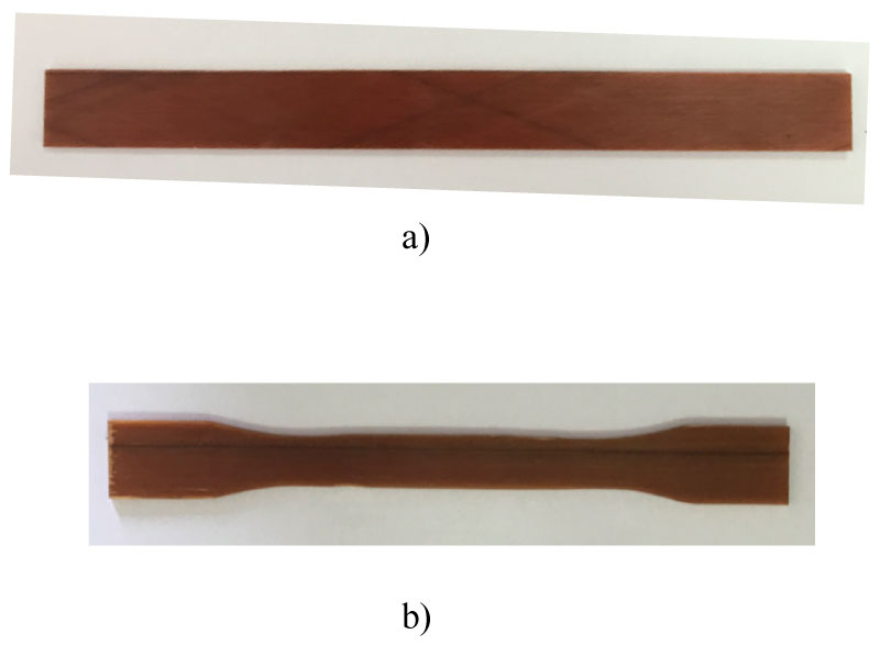
Figure 1: Test specimens used for a) The vibrating....
Test specimens used for a) The vibrating beam technique: and b) The tensile test.
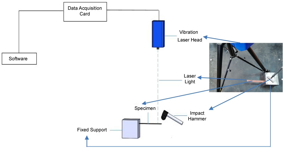
Figure 2: The vibrating beam set-up for the specimens....
The vibrating beam set-up for the specimens with the clamped-free end conditions.
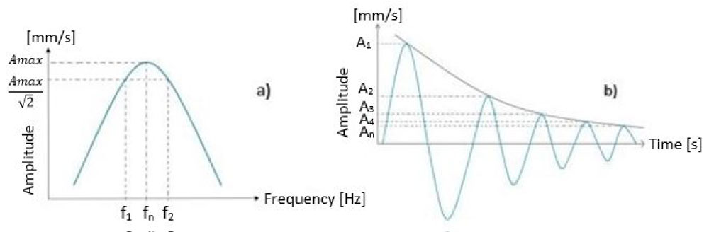
Figure 3: Schematic representations of the definitions....
Schematic representations of the definitions of: a) The half-power bandwidth method; and b) The logarithmic free decay method.
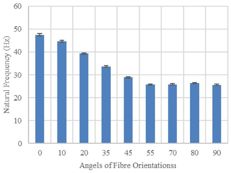
Figure 4: Variation of the natural frequency of the...
Variation of the natural frequency of the composite specimens with the different angles of the fibre orientations.
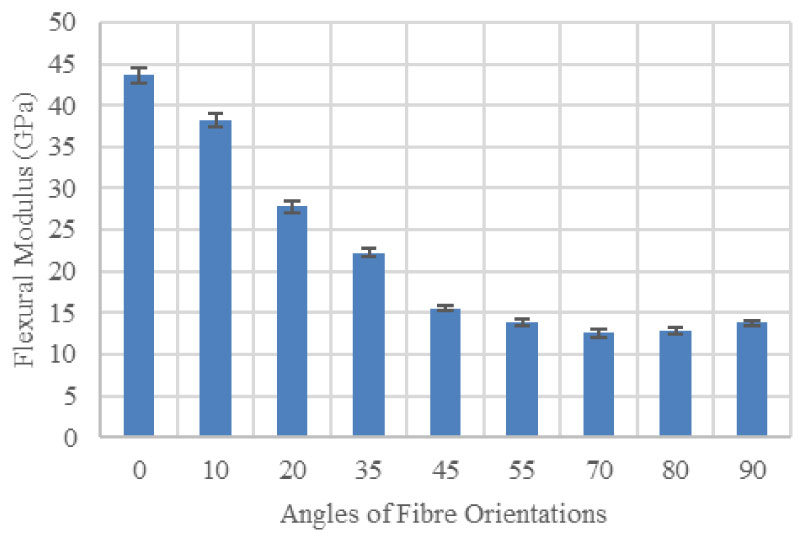
Figure 5: Variation of the flexural modulus of the...
Variation of the flexural modulus of the composite specimens with the different angles of the fibre orientations.
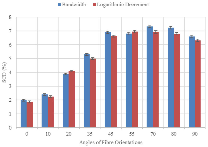
Figure 6: Variation of Specific Damping Capacity (SDC)....
Variation of Specific Damping Capacity (SDC) with the angles of the fibre orientations from the two methods.
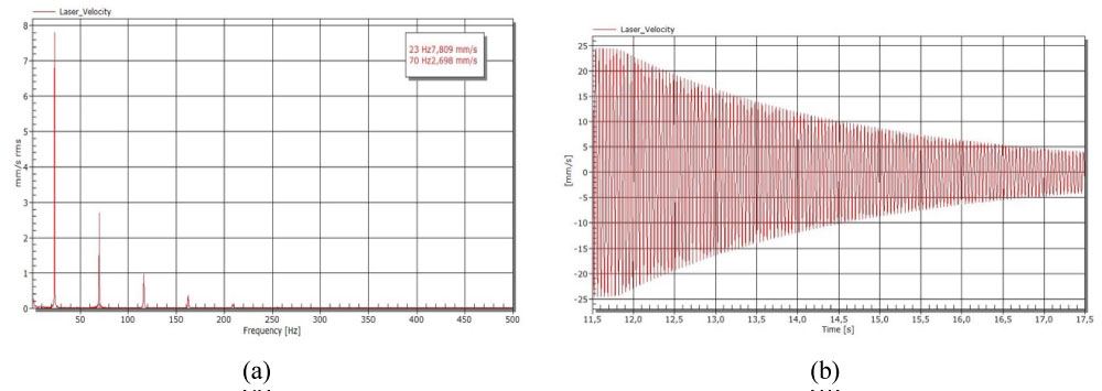
Figure 7: The response from the impacted specimens....
The response from the impacted specimens for the damping measurements of: a) The half-power bandwidth method; and b) The logarithmic free decay method.
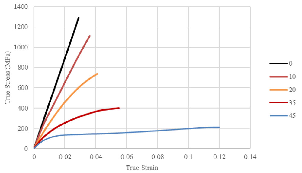
Figure 8: Typical tensile stress-strain curves....
Typical tensile stress-strain curves for the specimens with the 0°, 10°, 20°, 35° and 45° fibre orientations.
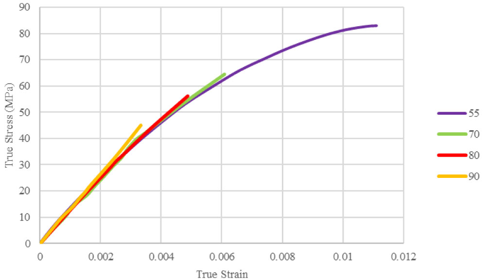
Figure 9: Typical tensile stress-strain curves for the...
Typical tensile stress-strain curves for the specimens with the 55°, 70°, 80° and 90° fibre orientations.
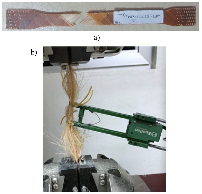
Figure 10: Typical failure modes of the specimens with....
Typical failure modes of the specimens with: a) The 45° fibre; b) The 0° fibre orientations.
Tables
References
- Zhang Z, Hartwig G (2002) Relation of damping and fatigue damage of unidirectional fibre composites. Int J Fatigue 24: 713-718.
- Audenino AL, Crupi V, Zanetti EM (2003) Correlation between thermography and internal damping in metals. Int J Fatigue 25: 343-351.
- Arunkumar MP, Pitchaimani J, Gangadharan KV, Leninbabu MC (2018) Vibro-acoustic response and sound transmission loss characteristics of truss core sandwich panel filled with foam. Aerosp Sci Technol 78: 1-11.
- Mellert V, Baumann I, Freese N, Weber R (2008) Impact of sound and vibration on health, travel comfort and performance of flight attendants and pilots. Aerosp Sci Technol 12: 18-25.
- Dewa H, Okada Y, Nagai B (1991) Damping characteristics of flexural vibration for partially covered beams with constrained viscoelastic layers. JSME Int J 34: 210-217.
- Saito H, Tani H (1990) Vibrations of bonded beams with a single lap adhesive joint. J Sound Vib 92: 299-309.
- Park TH (1997) Vibration and damping characteristics of a beam with a partially sandwiched viscoelastic layer. J Adhesion 61: 97-122.
- Douglas BE, Yang JCS (1978) Transverse compressional damping in the vibratory response of elastic-viscoelastic beams. AIAA J 16: 925-930.
- Qian GL, Hoa SV, Xiao X (1997) A vibration method for measuring mechanical properties of composite, theory and experiment. Compos Struct 39: 31-38.
- Guild FJ, Adams RD (1981) A new technique for the measurement of the specific damping capacity of beam in flexure. J Phys E Sci Instrum 14: 355-363.
- Rueppel M, Rion J, Dransfeld C, Fischer C, Masania K (2017) Damping of carbon fibre and flax fibre angle-ply composite laminates. Compos Sci Technol 146: 1-9.
- Rueppel M, Rion J, Dransfeld C, Masania K (2016) Damping of carbon fibre and flax fibre reinforced angle ply polymers. ECCM17- 17th European Conference on Composite Materials, Germany.
- Jen MHR, Kau YS, Ong CL (1994) Effect of matrix resin on the response in a centrally notched composite laminate. Compos Struct 29: 99-106.
- Manjunatha CM, Taylor AC, Kincloch AJ (2009) The effect of rubber micro- particles and silica nano-particles on the tensile fatigue behavior of a glass fibre epoxy composite. J Mater Sci 44: 342-345.
- Koratkar NA, Suhr J, Joshi A, Kane RS, Schadler LS, et al. (2005) Characterizing energy dissipation in single-walled carbon nanotube polycarbonate composites. Appl Phys Lett 87: 063102.
- Zhou X, Shin E, Wang KW, Bakis CE (2004) Interfacial damping characteristics of carbon nanotube-based composites. Compos Sci Technol 64: 2425-2437.
- Somen KB, Pavel P, Sunil CJ (2017) Enhanced vibration damping and dynamic mechanical characteristics of composites with novel pseudo-thermoset matrix system. Compos Sci Technol 179: 502-513.
- Li Y, Cai S, Huang X (2017) Multi-scaled enhancement of damping property for carbon fiber reinforced composites. Compos Sci Technol 143: 89-97.
- Adams RD, Bacon DGC (1973) Effect of fiber orientation and laminate geometry on the dynamic properties of CFRP. J Compos Mater 7: 402-408.
- Ni RG, Adams RD (1984) The damping and dynamic moduli of symmetric laminated composite beams: theoretical and experimental results. Compos Sci Technol 18: 104-121.
- Adams RD, Maheri MR (1994) Dynamic flexural properties of anisotropic fibrous composite beams. Compos Sci Technol 50: 497-514.
- Hadi AS, Ashton JN (1996) Measurement and theoretical modelling of the damping properties of a uni-directional glass/epoxy composite. Compos Struct 34: 381-385.
- Kadioglu F, Sekerci HU, Coskun T (2018) A novel method to measure dynamic properties of composite materials. AIAA SciTech Forum.
- Kadioglu F, Coskun T, Elfarra M (2018) Investigation of dynamic properties of a polymer matrix composite with different angles of fiber orientations. IOP Conf Ser: Mater Sci Eng 369: 012037.
- Machado J, Marques E, Campilho R, da Silva LFM (2016) Mode I fracture toughness of CFRP as a function of temperature and strain rate. J Compos Mater 51: 3315-3326.
- Daniel I, LaBedz R, Liber T (1981) New method for testing composites at very high strain rates. Exp Mech 21: 71-77.
- Al-Hassani S, Kaddour A (1998) Strain rate effects on GRP, KRP and CFRP composite laminates. Key Eng Mater 141-143: 427-452.
- Harding J, Welsh L (1983) A tensile testing technique for fibre-reinforced composites at impact rates of strain. J Mater Sci 18: 1810-1826.
- Taniguchi N, Nishiwaki T, Kawada H (2007) Tensile strength of unidirectional CFRP laminate under high strain rate. Adv Compos Mater 16: 167-180.
- Korber H (2010) Mechanical response of advanced composites under high strain rates. University of Porto, Portugal.
- Hou J, Ruiz C (2000) Measurement of the properties of woven CFRP T300/914 at different strain rates. Compos Sci Technol 60: 2829-2834.
- Den Hartog JP (1947) Mechanical Vibrations. McGraw-Hill Book Company Inc, New York, London.
- Singh MM (1993) Dynamic properties of fibre reinforced polymers exposed to aqueous conditions. University of Bristol, England.
Author Details
Paul O Jemitola* and Paul P Okonkwo
Department of Aerospace Engineering, Ankara Yildirim Beyazit University, Turkey
Corresponding author
Ferhat Kadioglu, Department of Aerospace Engineering, Ankara Yildirim Beyazit University, 06050, Ankara, Turkey.
Accepted: January 09, 2020 | Published Online: January 11, 2020
Citation: Kadioglu F, Coskun T (2020) Performance of Fibre-Reinforced Polymer Composite with Ply-Angle Orientations for Structural and Vibratory Applications. Int J Astronaut Aeronautical Eng 5:031.
Copyright: © 2020 Kadioglu F, et al. This is an open-access article distributed under the terms of the Creative Commons Attribution License, which permits unrestricted use, distribution, and reproduction in any medium, provided the original author and source are credited.
Abstract
In designing polymer composites, while their basic mechanical properties are seen as the primary interest for safety concern, their inherent damping values are seen as the secondary for human being comfort, safety and health. However, in today's advanced aerial and land vehicles, comport and health of passengers are as important as their safety. The aim of this work is to investigate the dynamic and also quasi-static behaviors of a glass fibre-reinforced polymer matrix composite, Hexply 913/33%/UD280, to be considered for structural as well as vibratory conditions. The specimens with different angles of fibre orientations (0, ± 10°, ± 20°, ± 35°, ± 45°, ± 55°, ± 70°, ± 80° and 90°) were manufactured from the composite prepreg and subjected to a vibrating beam test with the clamped-free boundary conditions. Two different methods, the half power bandwidth and the logarithmic free decay, were used to measure the damping values to be able to compare the results. A universal testing machine was used to obtain the stress-strain behaviors of the specimens. It has been revealed that the specimens with the ± 20°, ± 35° and ± 45° fibre orientations are able to produce high damping values with reasonable high maximum stresses. Especially the one with the ± 45 orientation is seen the best as it provides a high damping value and high strains to failure with an acceptable high stress. It is believed that such specimens are suitable for structural, vibratory and also impacted conditions, which is desired by many designers.
Keywords
Polymer matrix, Composites vibrating beam technique, Dynamic properties, Damping, Quasi-static behavior
Introduction
The fibre-reinforced polymer composites are preferred to be used in aerospace, automotive and many other industries due to their high specific density, stiffness and strength. Another important property of these materials is their damping values, related to their energy dissipation capabilities, desirable for vibration and noise control. Investigations carried out so far have shown that the inherent damping in materials has a positive impact on their fatigue life [1,2] and also on human being comfort, safety and health [3]. While basic mechanical properties of the composites mentioned above are seen as primary interest for design considerations, damping performance is seen as the secondary. However, in today's advanced aerial and land vehicles, comport and health of passengers are as important as their safety. For example, Mellert, et al. [4] found out that the impact of sound and vibration on health, travel comfort and performance of flight attendants and pilots have been proven to be significant. In this context, researchers' interest in damping value is increasing, and therefore correct measurement of this value is important for design considerations. It is believed that the most critical points for the reliable measurements are the selection of experimental set-up and its instrumentation. There are different types of transducers used for experimental studies to vibrate the specimen and to measure its response. For example, Dewa, et al. [5] investigated the partial cover effect on simply supported beams using an electromagnetic exciter and eddy current type gas sensors as transducers, whilst Rao and Crocker [6] employed an impact hammer with an attached force transducer to excite the single lap joint configurations with the same end conditions, the response being measured by a mini-accelerometer. For the clamped-free end conditions, Park [7], and Douglas and Yang [8] used similar instrumentation to investigate the constrained layer treatment while Qian, et al. [9] studied the same with plates. An alternative free-free beam method was improved by Guild and Adams [10], in which flat coils attached to each end of a beam were placed within the fields of permanent magnets. An alternating current through one coil caused the beam to vibrate, and the corresponding motion of the other coil induced a voltage proportional to its velocity. Due to its useful contribution to the structures, there are many efforts to increase the damping value in the composite materials using a aforementioned techniques and instrumentations [11-16]. Their points of interest mainly focus on matrix, interfacial between fibre and matrix, inter-laminar effects and stacking sequences [12,13]. Koratkar, et al. [15] measured more than 1000% increases in the loss modulus but a little reduction in the storage modulus when polycarbonate was enhanced by 2% weight fraction of single-walled carbon nanotubes (SWNTs). It was believed that frictional sliding at the SWNT interfaces was the reason for the enhanced energy dissipation. This was supported by the analysis of Zhou, et al. [16], who developed a model for the frictional sliding damping mechanism based on interfacial frictional motion between the nanotubes and the polymer matrix. Somen, et al. [17] used a novel liquid Methylmethacrylate (MMA) thermoplastic resin to enhance vibration damping of a composite made up of thick and thin plies of carbon fibres. After developing the novel composite system, the liquid MMA was found to be 27% more efficient in improving the structural damping compared to the epoxy resin. In another work [11], the damping behavior of continuous carbon fibre and flax fibre reinforced polymer (CFRP and FFRP) composites was studied by comparing angle-ply laminates. The results showed that about 2-3 times better damping of FFRP compared to CFRP at low frequency and low strain, and that the damping of both materials increases with increasing angle-ply orientation below 300 Hz. In a similar works [18], a multi-scaled methodology by using flax fibres and carbon nanotubes (CNTs) was proposed to enhance the damping property of carbon fibre reinforced epoxy composites. The damping property was measured by free vibration test and the strength and modulus were obtained by tensile and flexural tests. Effects of stacking sequences of flax fibres and the addition of CNTs on both the damping property and the mechanical properties of carbon fibre reinforced composites were investigated. Results clearly showed that the damping property of carbon fibre reinforced composites was improved greatly by laying flax fibres on the outmost layers of the composites. With the addition of CNTs, the damping property was further enhanced.
Another way to find out high damping values of the composite materials is to investigate their effects of fibre orientations. For instance, Adams and Bacon [19] obtained a maximum value of damping at 35° fibre orientation for carbon fibre-reinforced composite, but Ni and Adams [20] found the maximum value at the 60°. A similar work was carried out by Adams and Maheri [21], which yielded the maximum value at 75° fibre orientation. Glass fibre-reinforced epoxy matrix composites with different fibre orientations were experimentally studied by Hadi and Ashton [22], and the maximum value was found at the 300 orientation. In a different work, the value was obtained at the 90° [11]. However, when a non-contact measurement systems [23,24] were introduced to the experimental set-up, it was found that it was not possible to obtain the maximum value in the specimens with the angles smaller than the 45°.
Fibre-reinforced polymer composites have also been subjected to the destructive tests under different strain rates to evaluate their mechanical response [25-27]. It was found that while the tensile properties of unidirectional composites, dominated by the fibre, were not affected by the strain rate, the opposite was the case for the transverse direction, dominated by the matrix, [28-30]. In another work [31], it was concluded the properties dominated by the matrix are: Compression strength, Poisson's ratio, shear modulus and shear strength, and the properties dominated by the fibres are: Tensile modulus and strength which are virtually rate independent. The way to assess such composite materials for structural applications is to subject them to the tensile, compression and bending tests.
The aim of this study is to investigate the dynamic and quasi-static properties of a glass fibre-reinforced polymer matrix composite, to be considered for both vibratory and also structural applications. This will be done by altering the orientation angles of fibres, balanced and symmetric. The dynamic properties were found via a vibrating beam technique with an instrumented impact hammer and a vibration laser head. A non-contact response from the impacted specimens with clamped-free end conditions was measured, thanks to the laser head. Two different methods, the half power bandwidth and the logarithmic free decay, were used to measure the damping values to be able to see repeatable and comparable results. The composite specimens with different angles of fibre orientations was also subjected to the quasi-static tensile test to measure their basic mechanical properties. The results from the quasi-static and the vibrating beam tests were evaluated with a special interest in the high damping and also high maximum stress values so that the data obtained from this study could help the researchers with structural and modal designs.
The Experimental Works
The specimens
The material used in this study was a glass fibre-reinforced polymer matrix composite, Hexply 913/33%/UD280, produced by Hexcel, and the cure conditions for the prepreg of the composite was 130 °C for 120 minutes under a pressure of 5 bars. The specimens with 0°, ± 10°, ± 20°, ± 35°, ± 45°, ± 55°, ± 70°, ± 80° and 90° fibre orientations were machined from the cured plates with 10 layers, and the details of the specimens for the vibration test are shown in Table 1. After the specimens were vibrated non-destructively, the same ones as shown in Figure 1a, were machined to the ASTM D638 dimensions as shown in Figure 1b, and then subjected to the quasi-static tensile test. The two tests were carried out under a controlled environment, at room temperature (23 °C) and 50% relative humidity, to avoid environmental effects on the specimens, and about four specimens of each type were tested to see if the results are repeatable.
The test set-up
For the dynamic measurements of the specimens, a vibrating beam technique shown in Figure 2 was used. The experimental set-up includes an instrumented impact hammer, 8206 Bruel & Kjaer, to generate impulse and a non-contact laser head, Optomet NOVA-Series: SWIR Digital Laser Vibrometer, to pick up the response from the specimen. The impacted specimen is aimed to give its natural frequencies within a required frequency domain, via some distinguished peak values of the amplitude, depending on the mode shapes. A sophisticated data acquisition card, HBM QuantumX MX410B, was used to collect the digital values of velocity (amplitude) versus time, provided by the laser head which is also able to give displacement values. The set-up is supported by a software, HBM Catman data acquisition software (DAQ), to process the data according to the required output format for visualization and analysis. The natural frequency, elastic modulus and damping values of the specimens could be measured easily via the technique. For the damping values, two different methods, the half power bandwidth and the logarithmic free decay, were used, and more details about the methods are explained below. It is important to note that the specimens with the clamped-free end conditions were placed into the fixed support properly and the clamped part was tightened firmly, which is crucial for reliable measurements of the damping values.
Also, the specimens prepared according to the ASTM D638 standard specifications were subjected to the quasi-static tensile test. For this purpose, an universal tensile testing machine, BESMAK BMT-E 100 kN, was used with a constant crosshead speed of 2 min/mm. For actual measurements of strains, an axial extensometer, Model 3442 Epsilon, was applied to the specimen surface, and then true tensile stress-strain curves of each specimen were obtained through the software of the test machine.
Theory
Measurement of flexural modulus
For every solid obeying Hook's Law, there is a specific natural frequency which is a function of its elastic modulus, geometry, density and the mode number. The natural frequency of a beam, is found as [32]:
Where 1.875 is the 1st eigenvalue for clamped-free end conditions, n is the mode number, E is the flexural modulus, I is the second moment of area, l is the length, is the mass density, t is the thickness, and b is the width of the beam. The flexural modulus of the specimen was measured using equation (1), and only the first (fundamental) mode was taken into account for all the measurements.
Measurement of damping
For an elastic solid structure, damping is defined as the conversion of mechanical energy into thermal energy, and it is defined in a number of different, yet related ways [33]. In this study, the half-power bandwidth method and the free decay method were used for measuring the damping values, and the results were compared to see if they are in agreement.
The half-power bandwidth method
This is determined from the curve of velocity amplitude against frequency, obtained when the specimen is impacted by the hammer. The 'half-power bandwidth' is (f2-f1) where f2, f1 are the frequencies at which the amplitude falls to 1/√2 of its maximum value, reached at fn, the resonant frequency. The loss factor, η is defined as,
A schematic representation of the definition is illustrated in Figure 3a).
The logarithmic free decay method
This is found by observing the decay of free vibrations (a 'free decay' method). The specimen is vibrated using the hammer, and a trace obtained of vibration amplitude against time, as illustrated in Figure 3b), is obtained. The logarithmic decrement, δ is then given by:
Where A1 is the amplitude of the first cycle, and An+1 is the amplitude of the (n+1)th cycle.
For convenience, damping is usually presented in Specific Damping Capacity (SDC), , which is defined as the ratio of the energy dissipated per cycle to the maximum elastic energy stored per cycle, per unit volume [21]. This ratio is usually expressed as a percentage.
For small damping, it is known there is relationship as follows [33],
Results and Discussion
The variation of natural frequencies of the specimens with the different angles of fibre orientation is shown in Figure 4. It is seen from the figure that the natural frequency is greatly dependent on the fibre orientations, and that small angles of fibres result in relatively high natural frequencies. From Equation (1), it is clear that the frequency is affected by the dimensions of the specimens, to eliminate this, the specimens tested have almost the same dimensions (see Table 1), which implies the change in the frequency is only attributed to the different angles of the orientation. While the maximum natural frequency is about 47 Hz for the specimens with the ° orientation, the minimum value is around 25 Hz for those with the 90°. The figure clearly shows that there is a linear decrease in the frequency for the specimens with from the 0° up to the 55° orientations, and then it levels up for those with the fibre orientation angles bigger than the 55°.
The variation of flexural modulus with the fibre orientations is shown in Figure 5, the response is similar to that shown in Figure 4. A maximum value of the modulus, about 45 GPa, is found for the specimens with the 0° orientations, and the minimum value was about 13 GPa for those above the 45° orientations.
As explained above, for the damping measurements of the specimens, two different methods, the logarithmic free decay and half power bandwidth, were used, and the results are presented in Figure 6, which is the variation of SDC against the different angles of the fibre orientation. The figure shows that the results are totally opposite to those shown in Figure 5; while the maximum values of the SDC are about 7% for the specimens with the higher angles, 45°, 55°, 70°, 80° and 90°, the minimum value is about 2% for those with the 0°. These results are directly related to the mechanical properties of the fibre and the matrix forming the content of the composite material. It is clear that the matrix as a polymer has a high damping value, but a low value of elastic modulus, however, the specimens controlled by the behavior of the fibres should give low damping, but high elastic modulus. It is seen that the damping results obtained from the two methods are comparable, in general. Typical responses of the specimens measured by the laser head, after impacted by the hammer, are shown in Figure 7a) and Figure 7b), the cases for the bandwidth and for the free decay methods, respectively. It should be noted that the first Figure (Figure 7a)) indicates the natural frequencies between 1st and 4th modes, and that only the 1st mode was used for the measurements. The damping values of the specimens were obtained by using Equations (2) and (3), and then converted into SDC by using Equation (4).
To get a clear idea about their stress-strain behaviors, the true stress-strain curves of the composite specimens with the different fibre orientations are shown in Figure 8 and Figure 9 separately. While the former indicates those with the 0°, 10°, 20°, 35° and 45° angles, the latter is for those with the 55°, 70°, 80° and 90° ones. It is clear that the former represents considerable high stresses with high strains to failure, which implies high potential for structural applications. However, the letter has relatively low stresses as well as low strains to failure, implying poor performance. The specimens with 0° and 10° angles represent the best structural performance but have relatively low damping values which is not desired by designers for vibratory conditions. On the other hand, those with the 55°, 70°, 80°and 90° orientations have remarkable high damping values, but their structural performance is too low for load bearing capacity. It is believed that those with the 20°, 35° and 45° fibre orientations can be considered for structural as well as vibratory applications as they possess both high stress levels and also high damping values. The main reason for this, as explained above, is because the specimens with over 45° angles are controlled by the matrix material which possess usually low strength but high damping values, yet, those with 0° and 10° ones are mainly controlled by the fibres having low damping but high strength values. However, those with the 20°, 35° and 45° represent the properties of the both the matrix and the fibres as well, so it is possible to obtain a high value of damping with desirable stress levels.
Table 2 shows the data obtained from the both tests, the non-destructive vibrating beam technique and the quasi-static tensile test applied to the specimens to failure. From the table, it is seen that the maximum tensile stress is about 1290 MPa obtained from the specimen with the 0° fibre orientation, but the minimum stress, 45 MPa, is from the one with the 90°. The other values are somewhere between these two orientations depending on the fibre angles. The values of the elastic modulus obtained from two different tests seem reasonably comparable although one test was in flexure (vibration) the other one was in quasi-static tensile. The maximum value of the strain to failure obtained from the tensile test is about 0.12 for the specimen with the 45° angle while the minimum value is from the one with the 90° angle, about 0.003. The strain values above and below the 45° angle tend to decrease implying the most useful specimens could be the one with this angle (45°) in terms of producing large displacements. The specific damping capacity (SDC) values of the specimens obtained from the low stress levels using the vibration test are seen in the last column of the table and the necessary assessment about the SCD was made above.
From all the assessments made so far, it would be fair to say that the 45° specimens is unique for both structural as well as vibratory applications as it is able to produce a high damping value, about 7% SDC, with a reasonable high stress level, about 210 MPa and also with high strain value to failure, about 0.12. Such specimens yielding large displacement under the applied load can also be considered for crashworthiness as it is able to absorb impacted energy effectively.
In general, the failure mechanisms of the specimens were dominated by the fibre orientation, which can be seen in Figure 10a for those with the 45° orientation. While nearly all the specimens failed with respect to their relevant fibre angles, those with the 0° ones failed in chaotic way due to the highly stressed fibres under the applied load, shown in Figure 10b.
Conclusions
In today's advanced aerial and land vehicles, comport and health of passengers are as important as their safety. Therefore, it is important to be selective about the materials to be used as components of such vehicles. The polymer composites considered as one of the best choices for such applications have a good potential to provide both high strength due to their abilities of fibres and also high damping performance due to its matrix constituent. In this study, suitable parameters of such a composite material are sought through different angle of fibre orientations. For this purpose, the composite specimens with the 0°, ± 10°, ± 20°, ± 35°, ± 45°, ± 55°, ± 70°, ± 80° and 90° orientations were investigated to be able to see their potentials for structural as well as for vibratory applications. These were assessed by using a non-destructive vibrating beam technique and a destructive quasi-static tensile test.
The results show that the specimens with the ± 20°, ± 35° and ± 45° fibre orientations can be used for both structural as well as vibratory applications as they possess high maximum stresses and also high damping values. While those with the 0° and 10° angles produce a maximum amount of stresses, those with the ± 55°, ± 70°, ± 80° and ± 90° ones have desirable high damping values but drastically low amount of stresses, which can cause some safety problems if to be used for structural purposes. On the other hand, the specimen with the ± 45° orientation presents exceptional dynamic and quasi-static behaviors, which can be considered for structural, vibratory and also impacted applications due to its high stress, damping value and large strains to failure.
Acknowledgments
We would like to thank to the Turkish Aerospace Industry for supporting the current work.