
International Journal of Astronautics and Aeronautical Engineering
(ISSN: 2631-5009)
Volume 5, Issue 2
Original Article
DOI: 10.35840/2631-5009/7540

Article Formats
Cooling of Electromechanical Actuator Motors by Air Recirculation
Table of Content
Figures
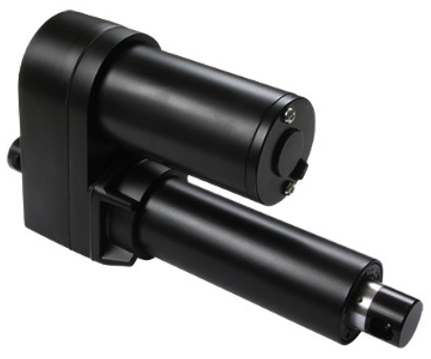
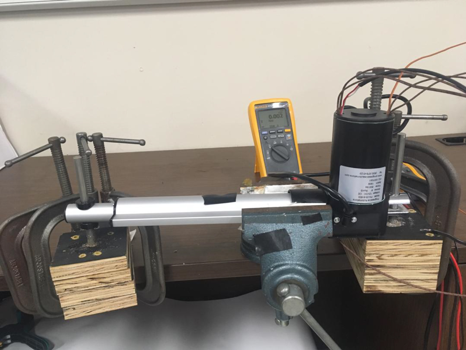
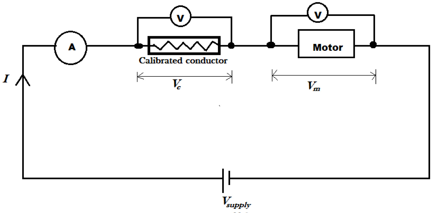
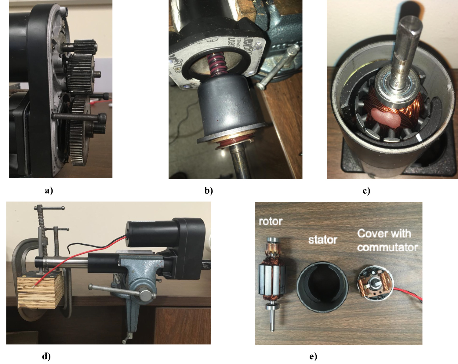
Figure 4: DMA-24-5-B-IP65 motor parts and experimental....
DMA-24-5-B-IP65 motor parts and experimental set up: (a) DMA-24 Gear arrangement; (b) Ball screw in actuator; (c) Rotor and stator assembly; (d) EMA in a jammed position; (e) Internal components within housing of EMA.
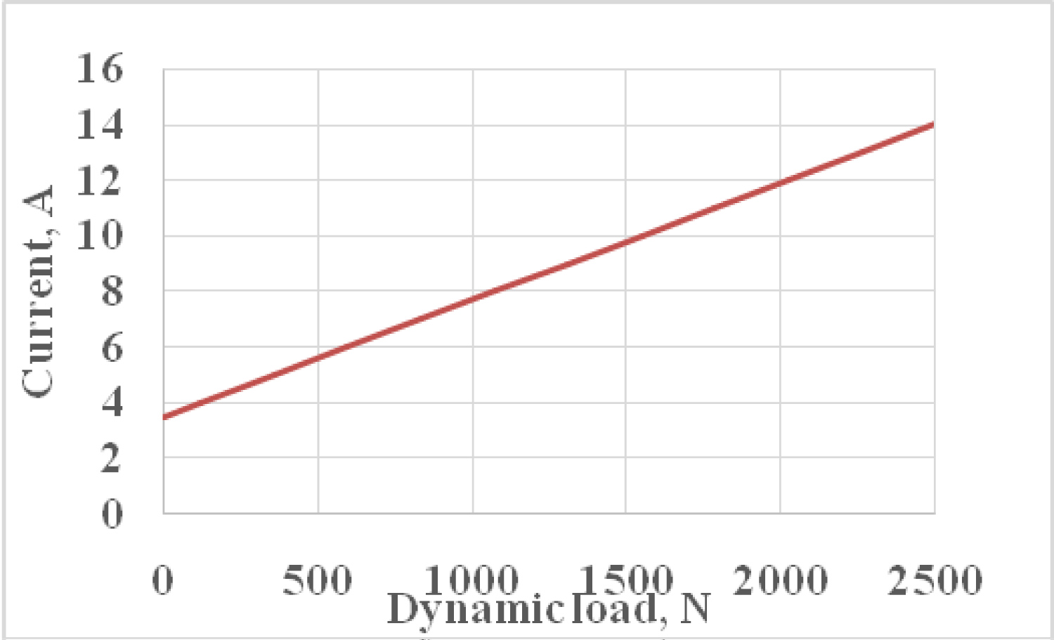
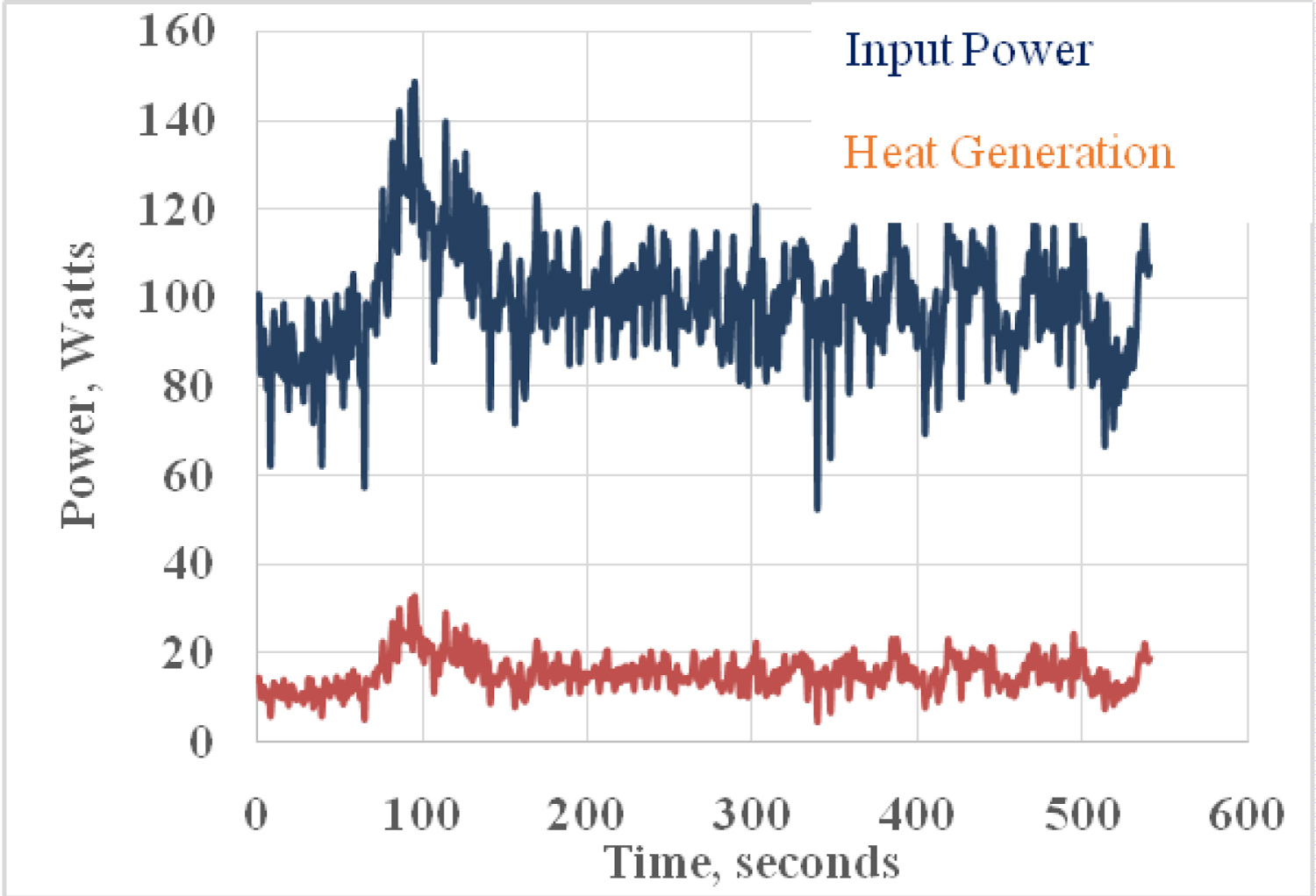
Figure 6: Power consumption and dissipation profile....
Power consumption and dissipation profile at no external load.
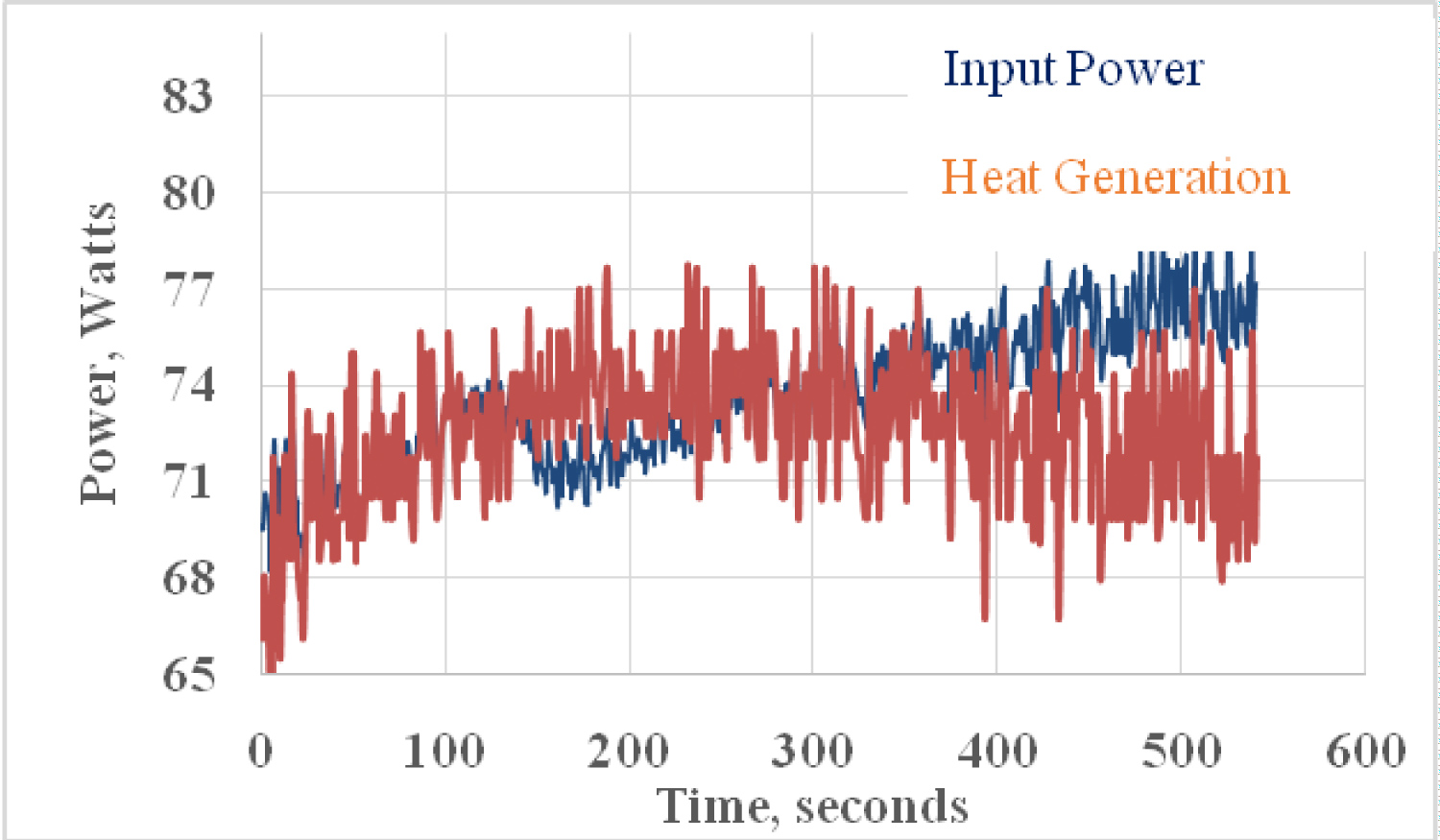
Figure 7: Power consumption and dissipation...
Power consumption and dissipation at full static load.
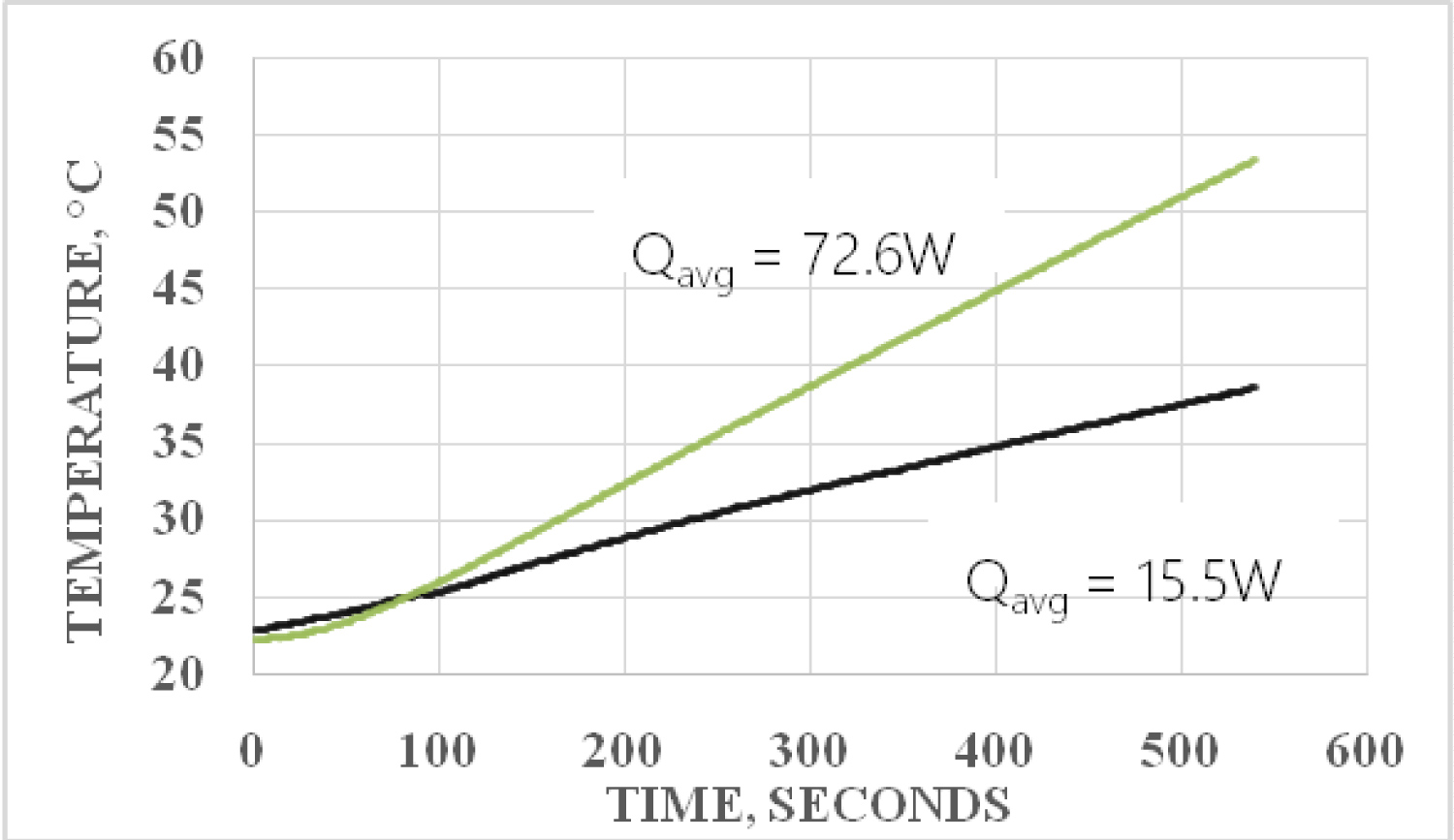
Figure 8: Air temperature inside DMA24 motor housing...
Air temperature inside DMA24 motor housing at full static load and no load (free spinning conditions).
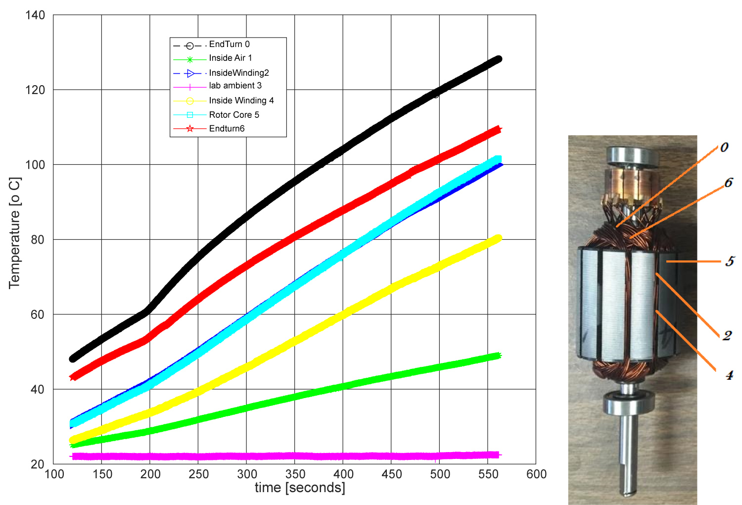
Figure 9: Transient temperature profile of PA-003 at....
Transient temperature profile of PA-003 at Q = 60.12 W and temperature probe locations.
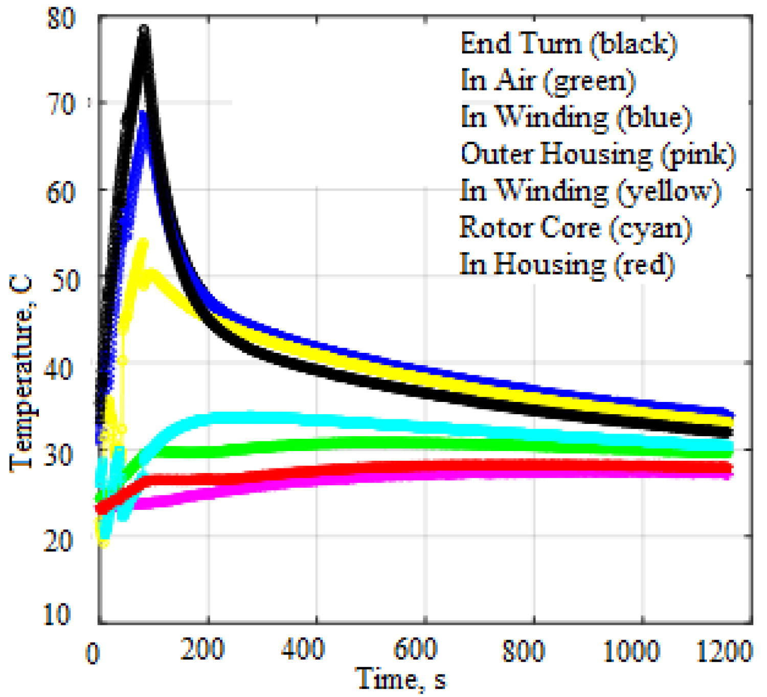
Figure 10: Temporal temperature profiles at Q = 66 W...
Temporal temperature profiles at Q = 66 W for 80 s followed by cooling by natural convection.
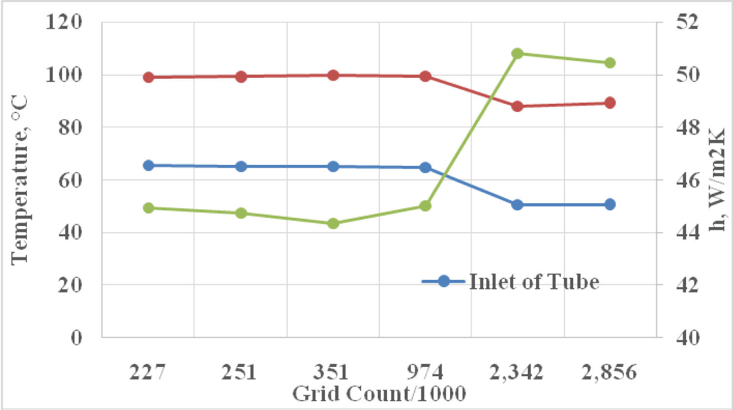
Figure 11: Grid independent analysis of the computational...
Grid independent analysis of the computational model.
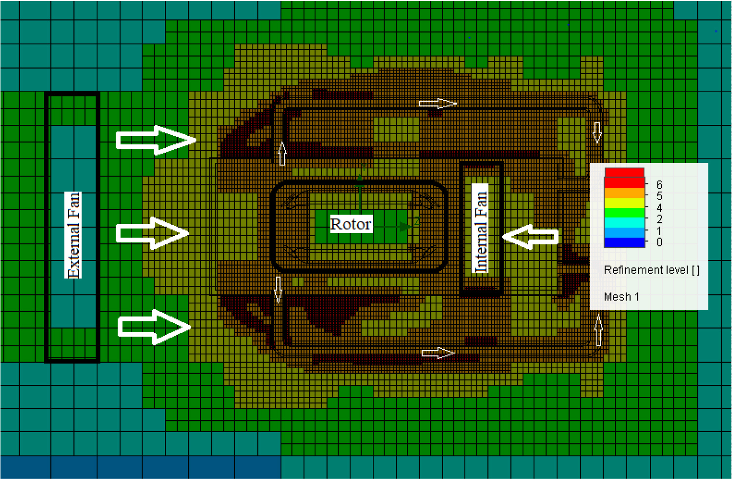
Figure 12: Grid used to calculate the results demonstrated...
Grid used to calculate the results demonstrated in the results section.
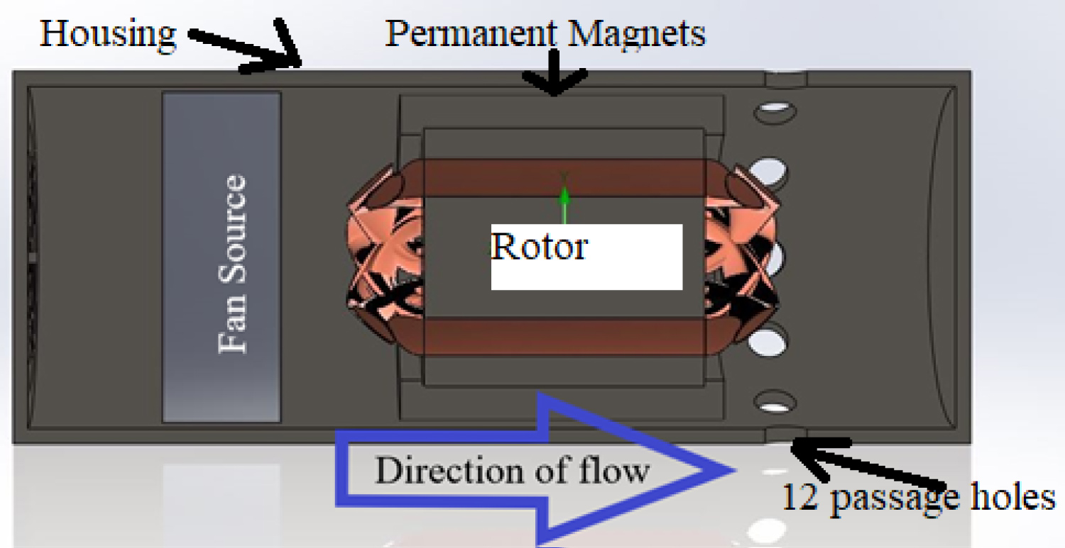
Figure 13: Section view through the midplane of the....
Section view through the midplane of the EMA housing.
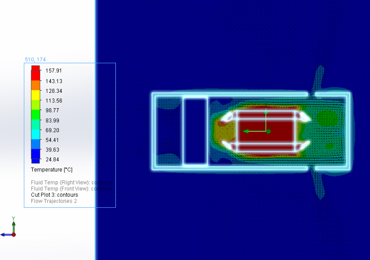
Figure 14: Temperature contours using the ETRI Fan...
Temperature contours using the ETRI Fan at steady state conditions.
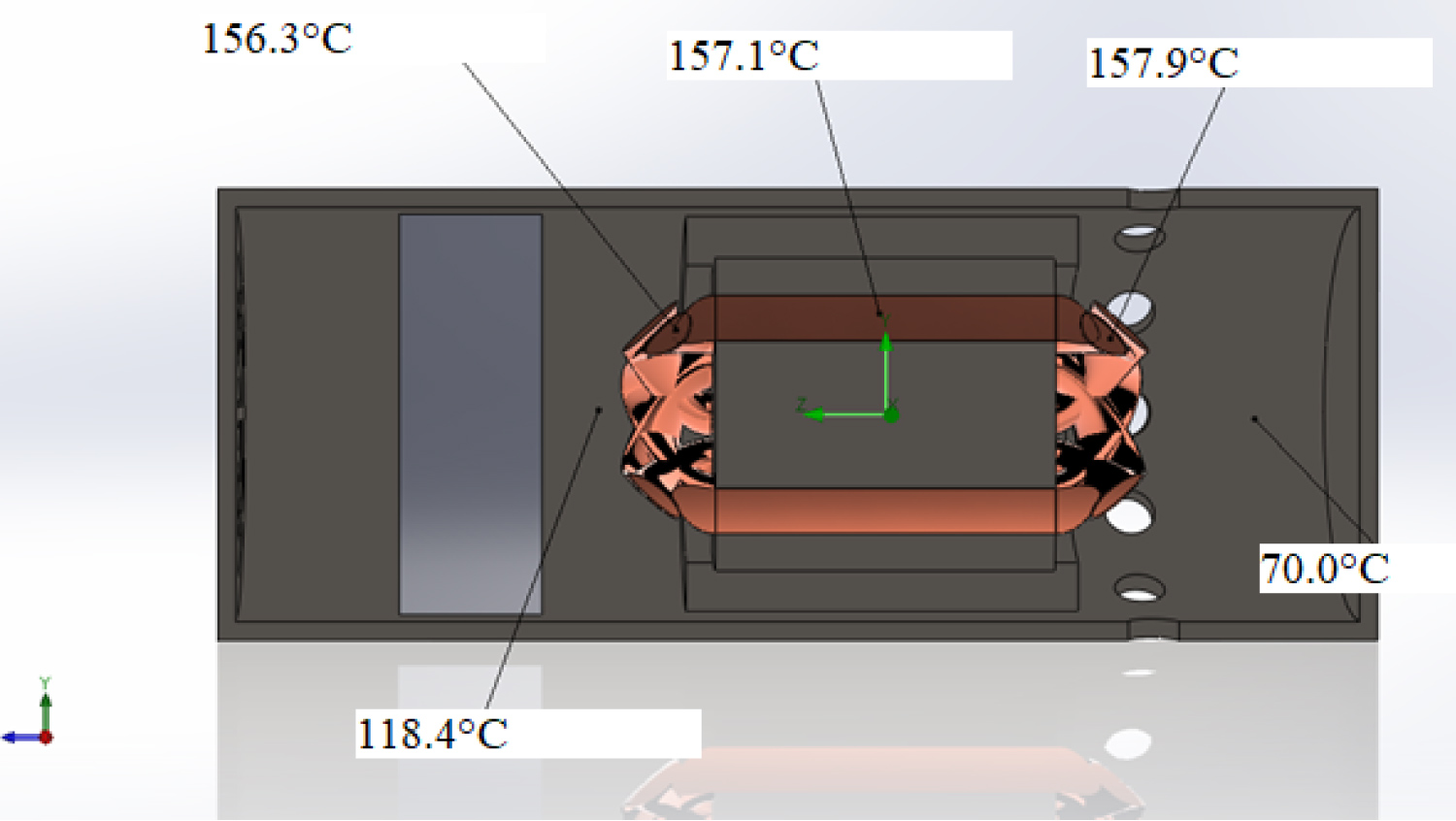
Figure 15: ETRI Fan temperature probes placed at and around....
ETRI Fan temperature probes placed at and around the motor at steady state.
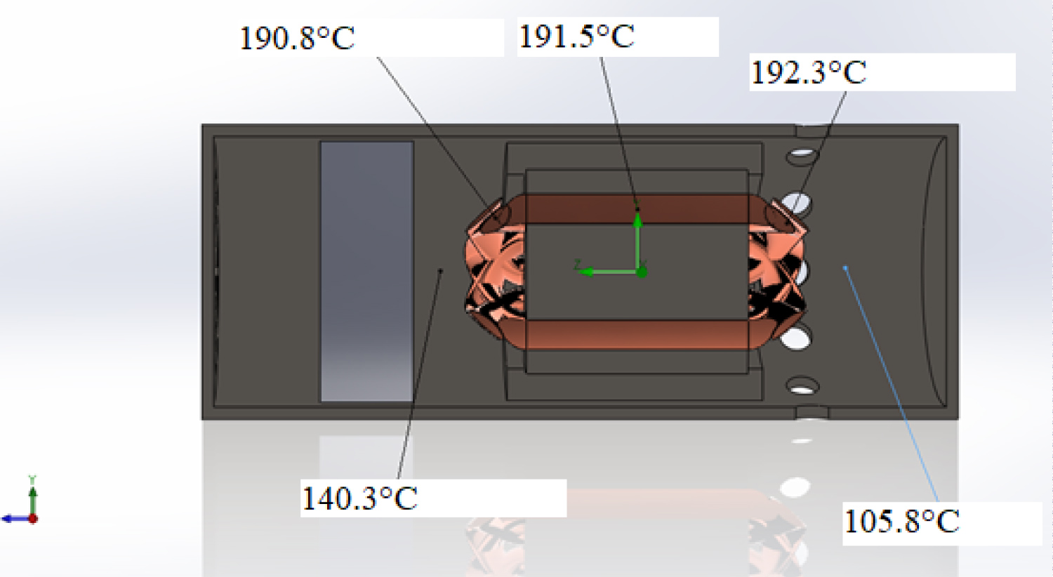
Figure 16: Temperature probe measurements at and around....
Temperature probe measurements at and around the motor using the mechatronics fan at steady state.
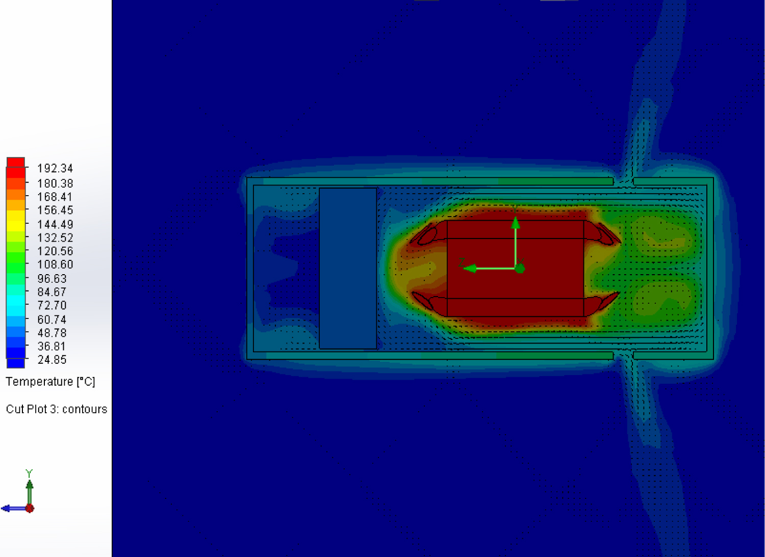
Figure 17: Temperature contour of the motor being cooled...
Temperature contour of the motor being cooled by Mechatronics Fan at steady state.
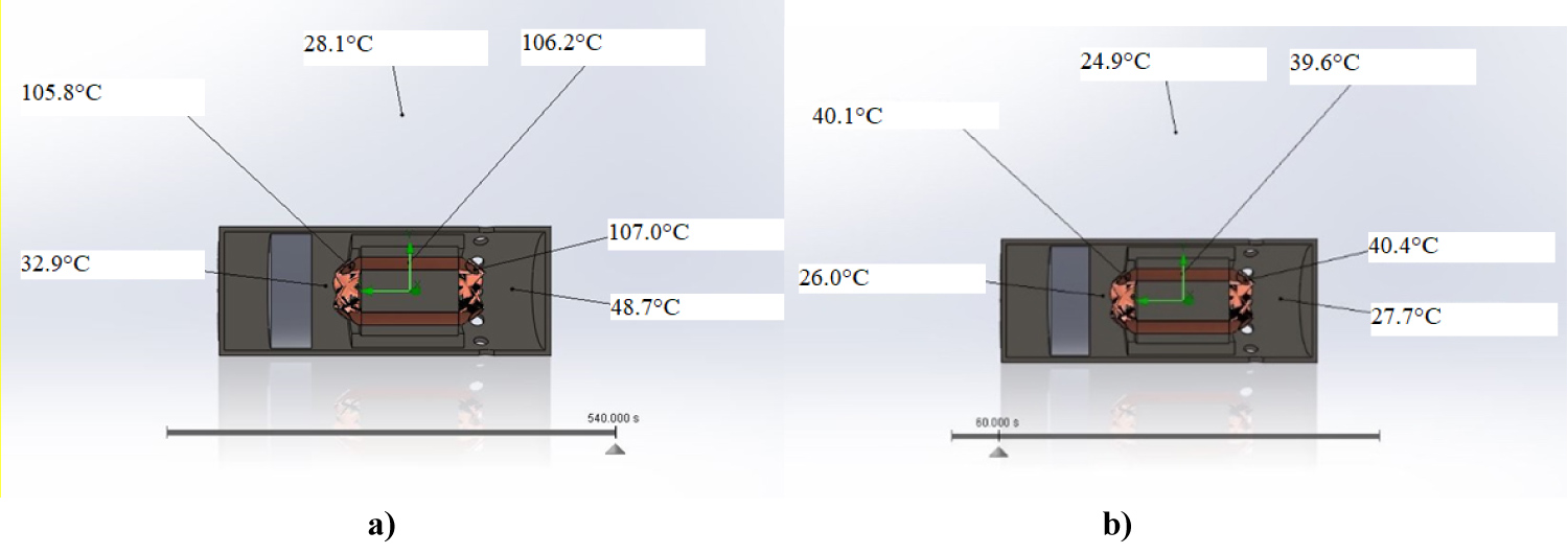
Figure 18: (a) Temperature probe measurements at t = 60 s; (b)...
(a) Temperature probe measurements at t = 60 s; (b) Temperature probe measurements at t = 540 s.
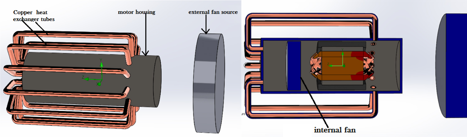
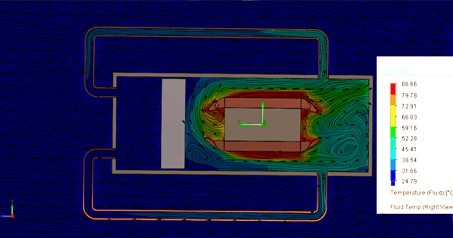
Figure 20: Temperature contours with velocity streamlines...
Temperature contours with velocity streamlines and quiver plots.
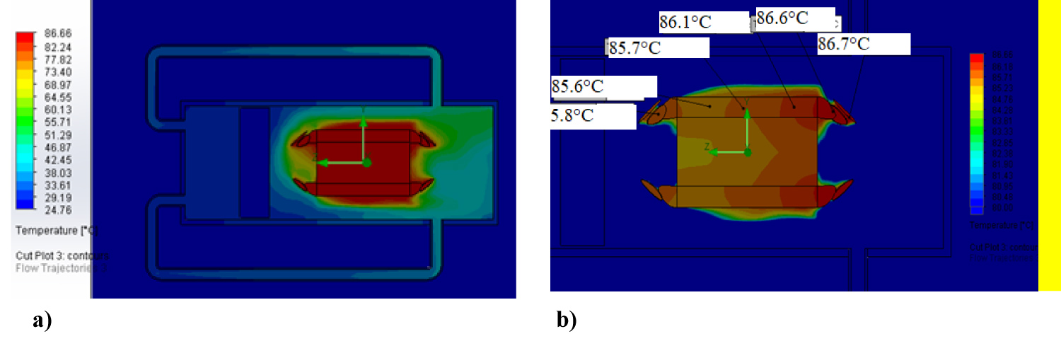
Figure 21: (a) Temperature contours at 300 s with...
(a) Temperature contours at 300 s with demonstrating maximum and minimum temperatures; (b) Temperature contours for a narrow range of temperatures identify the temperature distribution on the rotor.
Tables
Table 1: Manufacturer supplied specifications of DMA-24-5-B-IP65 (Source product catalog: www.transmotec.com) and PA 003 (source: progressiveautomations.com).
References
- SC Jensen, GD Jenney, D Dawson (2000) Flight test experience with an electromechanical actuator on the F-18 systems research aircraft. (19th edn), Digital Avionics Systems Conference, Proceedings.
- A Garcia, I Cusido, JA Rosero, JA Ortega, L Romeral (2008) Reliable electro-mechanical actuators in aircraft. IEEE Aerospace and Electronic Systems Magazine 23: 19-25.
- J Fu, JC Mare, YL Fu ( 2017) Modelling and simulation of flight control electromechanical actuators with special focus on model architecting, multidisciplinary effects and power flows. Chinese Journal of Aeronautics 30: 47-65.
- X Yu, Y Zhang (2015) Design of passive fault-tolerant flight controller against actuator failures. Chinese Journal of Aeronautics 28: 180-190.
- DH Lim, SC Kim (2014) Thermal performance of oil spray cooling system for in-wheel motor in electric vehicles. Applied Thermal Engineering 63: 577-587.
- T Davin, J Pelle, S Harmand, R Yu (2015) Experimental study of oil cooling systems for electric motors. Applied Thermal Engineering 75: 1-13.
- AS Fawzal, RM Cirstea, TJ Woolmer, M Dickison, M Blundell, et al. (2018) Air inlet/outlet arrangement for rotor cooling application of axial flux PM machines. Applied Thermal Engineering 130: 1520-1529.
- DP Kothari, IJ Nagrath (2004) Electric machines. Tata McGraw-Hill.
- W Tong (2014) Mechanical design of electric motors. CRC Press, Taylor & Francis Group, Boca Raton, 702.
- S Wang, Y Li, YZ Li, J Wang, X Xiao, et al. (2016) Transient cooling effect analyses for a permanent-magnet synchronous motor with phase-change-material packaging. Applied Thermal Engineering 109: 251-260.
- Y Sun, S Zhang, W Yuan, Y Tang, J Li, et al. (2019) Applicability study of the potting material based thermal management strategy for permanent magnet synchronous motors. Applied Thermal Engineering 149: 1370-1378.
- H Wang, P Bai, H Zhou, N Li, H Liao, et al. (2019) An integrated heat pipe coupling the vapor chamber and two cylindrical heat pipes with high anti-gravity thermal performance. Applied Thermal Engineering 159: 113816.
- M Arik, J Petroski, S Weaver (2002) Thermal challenges in the future generation solid state lighting applications: Light emitting diodes. Eighth Intersociety Conference on Thermal and Thermomechanical Phenomena in Electronic Systems, Cat. No.02CH37258, 113-120.
- VV Zhirnov, RK Cavin, JA Hutchby, GI Bourianoff (2003) Limits to binary logic switch scaling- a gedanken model. Proceedings of the IEEE 9: 1934-1939.
- L Zhu, H Tan, J Yu (2013) Analysis on optimal heat exchanger size of thermoelectric cooler for electronic cooling applications. Energy Conversion and Management 76: 685-690.
- R Kabir, K Kaddoura, P McCluskey, JP Kizito (2018) Investigation of a cooling system for a hybrid airplane. AIAA/IEEE Electric Aircraft Technologies Symposium.
- X Chen, H Ye, X Fan, T Ren, G Zhang (2016) A review of small heat pipes for electronics. Applied Thermal Engineering 96: 1-17.
- OYWA Kamal Kaddoura, JP Kizito (2018) Effect of screen layers and orientations on mesh wicked heat pipes. (18th edn), Annual Early Career Technical Conference, University of Alabama Birmingham, USA.
- N Putra, WN Septiadi (2017) Improvement of heat pipe performance through integration of a coral biomaterial wick structure into the heat pipe of a CPU cooling system. Heat and Mass Transfer 53: 1163-1174.
- N Putra, R Saleh, WN Septiadi, A Okta, Z Hamid (2014) Thermal performance of biomaterial wick loop heat pipes with water-base Al2O3 nanofluids. International Journal of Thermal Sciences 76: 128-136.
- N Putra, WN Septiadi, H Rahman, R Irwansyah (2012) Thermal performance of screen mesh wick heat pipes with nanofluids. Experimental Thermal and Fluid Science 40: 10-17.
- N Putra, B Ariantara (2017) Electric motor thermal management system using l-shaped flat heat pipes. Applied Thermal Engineering 126: 1156-1163.
- W Wu, YR Lin, LC Chow, Q Leland (2014) Fan performance characteristics at various rotational speeds and ambient pressures. Presented at the SAE Technical Paper Series.
- JJJ Corona, AA Kwarteng, G Warwick, K Kaddoura, O Mesalhy, et al. (2018) Testing of a cooling fan for wing-bay electro-mechanical actuators. ASME 2018 5th Joint US-European Fluids Engineering Division Summer Meeting, V002T14A016.
- O Mesalhy, C Rath, D Rini, J Kizito, Q Leland, et al. (2019) A parametric fin structure design studys for cooling aerospace electro-mechanical actuators with high-speed axial fans. Heat and Mass Transfer.
- A Hughes, B Drury (2013) Electric motors and drives. (4th edn), Fundamentals, Types and Applications.
Author Details
JJ Corona, A Akuoko Kwarteng, Kamal A Kaddoura and JP Kizito*
Department of Mechanical Engineering, North Carolina Agricultural and Technological State University, USA
Corresponding author
JP Kizito, Department of Mechanical Engineering, North Carolina Agricultural and Technological State University, Greensboro, NC 27411, USA.
Accepted: September 19, 2020 | Published Online: September 21, 2020
Citation: Corona JJ, Kwarteng AA, Kaddoura KA, Kizito JP (2020) Cooling of Electromechanical Actuator Motors by Air Recirculation. Int J Astronaut Aeronautical Eng 5:040.
Copyright: © 2020 Corona JJ, et al. This is an open-access article distributed under the terms of the Creative Commons Attribution License, which permits unrestricted use, distribution, and reproduction in any medium, provided the original author and source are credited.
Abstract
In this study, two generic electromechanical actuators were thermally investigated whilst resisting a steady load for nine minutes. The EMA's represent flap actuators that will be housed in the aircraft wing bay. The research aimed to identify temperature hotspots and overheating concerns followed by proposing cooling methods. The motors driving the EMA's have windings on the rotor separated from the stator and housing by an airgap clearance. The airgap imposed high thermal resistance and formed insulation around the stationary rotor; thus, containing high heat and temperature variations that needed to be managed. The study employed two modifications to the original structure of the motor to numerically evaluate viable cooling options. The first design option extends the housing of the EMA motor, embed an ETRI fan that draws air from the wing through the motor housing, and runs independently of the EMA rotor shaft. An alternative design had the same internally housed ETRI fan but cuts the motor air off from the wing bay by introducing copper heat exchanger tubes for recirculation.
Experimental work was done to identify the areas of concern for EMAs. The end windings reached 129 ℃ whilst the embedded portion of the windings stayed at 81 ℃. All scenarios were simulated in SOLIDWORKS Flow Simulation. Results revealed that the air passage cooling, and the copper tube heat exchanger encounter the highest temperature spot by 40.5 ℃ and 37.5 ℃, respectively. The cooling performances of both systems are practical cooling schemes. The open-air passage system draws air from the environment that can potentially contaminate the internal motor components. The copper tube heat exchanger preserves the original ingress protection of the EMA but requires greater design modifications and slightly decreased cooling capabilities.
Introduction
EMA's form the backbone of reliable power-by-wire actuation systems for both aerospace applications and they present a formidable alternative to eliminate hydraulic systems from aircraft and spacecraft [1]. The benefits include improved safety, efficiency, reliability, and maintainability as well as overall weight reduction. Power by wire in "More Electric Aircraft" (MEA) concepts seeks to systematically substitute hydraulic actuators by EMA's [2].
EMAs eliminate the necessity for central and local hydraulic circuits because it transmits motor power to the load via mechanical reducers such gearbox and nut-screw mechanisms [3]. Nevertheless, EMAs are yet to replace conventional hydraulic servo-actuators (HSA) in normal mode for safety-critical functions such as flight controls due to technical challenges such as weight and size constraints for integration, voltage spikes and current transients effects on stability of electrical networks, heat rejection for actuator thermal balance [3,4].
Thermal management of motor windings has been the focus ongoing research in recent years. This effort is commensurate with the need for a well-controlled temperature for the performance and safety of the motors. High temperatures beyond the insulation class limit of the windings cause the enamel to melt away leading to a shorting of the wires. The suitable mode of cooling depends on the motor capacity [5] as well as the duty cycle, whether continuous or short cycle duty. In general, the cooling methods for a motor can be divided into air-cooling and liquid-cooling. In this current study for instance, it was observed that proven cooling methods that were effective for continuously rotating motors would not necessarily work for the EMA's operating on short duty by default. The method of air-cooling mainly dissipates heat by fins on the surface of the casing and it is typical for low power machines, presenting the advantages of simple structure, low cost and easy maintenance [6,7]. The operating temperature of an electrical machine such as EMA's is a balance between heat generation and removal rates, thus a good thermal management scheme is required to boost performance and enhance reliability [8,9].
Wang, et al. [10] proposed a novel thermal management approach with phase change material (PCM) for a permanent magnet synchronous motor (PMSM) applied in the actuator systems of aircraft using a numerical approach. They were able to show that when the conventional motor casing was replaced by a paraffin-based enclosure, the effective time for the PMSM temperature control could be prolonged by approximate 32.7% when the motor works under a continuous mode and dissipating 270 W. The peak temperature of the PMSM could be decreased by 7.82 ℃ when the PMSM operates under a duty cycle of 0.67. Sun, et al. [11] applied a potting silicone gelatin to reduce the end windings temperature of a 53 kW permanent magnet synchronous motor, a modification which also altered the temperature distribution of the windings. For the original motor, the lowest temperature of the windings situated in the middle part of the windings which contacts with the stator through the slot paper directly. The lowest temperature however moved towards the end when potting silicone gelatin was applied to the windings. They explained that the potting material enhance the heat transfer from the end windings because it offered a solid contact to the casing. The peak operating temperature of the windings reduced by 27.3 ℃.
However, the incorporating electric, and hybrid methods into aerospace technologies means the addition of heat generating sources. As these methods become more intensive in a system, the reliability and lifetime of the technology are affected [12-15]. Heat pipes have been an attractive technique for thermal managers who aimed to cool hybrid technologies [16]. For instance, Faghri emphasized the simplicity of designing, controlling, and integrating heat pipes as a passive cooling mechanism for aerospace applications. Heat pipes are good thermal conductors that can carry excessive amount of waste heat energy through a small cross-sectional area and then releases the latent heat energy of the fluid to the ambient [17]. Heat pipes vary in their shape, working fluid, transport mechanism, and other aspect depending on their application. In aerospace application, capillarity driven heat pipes showed better performance than gravity driven heat pipes because of their independence of gravity [18]. Moreover, the thermal performance of a heat pipe could be enhanced in different manners as well. Heat pipes' performance could be enhanced on the interior level; Putra, et al. showed that the usage of biomaterial wicks and nanofluid particles enhance the performance of heat pipes [19-21]. On the exterior level, improvements could also be done by adding fins and forced convection [22].
Although heat pipes have been proven to be viable cooling options for EMAs, the current work is focused on using forced convection to provide the necessary cooling to the EMA. Due to the configuration of the EMA, the rotor is the component that experiences the hot spots; Therefore, passive cooling techniques (i.e. heat pipes) is not a viable option for cooling this type of EMA. Although heat pipes have been proven to be viable cooling options for EMAs, the current work is focused on using forced convection to provide the necessary cooling to the EMA. Due to the configuration of the EMA, the rotor is the component that experiences the hot spots; therefore, passive cooling techniques (i.e. heat pipes) are not a viable option for cooling this type of EMA. Work has been conducted in using fans for EMA cooling specifically for aerospace applications. In [23,24] scaling analysis was conducted to determine the effects of fans at variable pressure for cooling EMAs in aerospace. Also combined cooling techniques by using fans and finned structures yield desirable results to maintain EMAs at operable temperatures [25]. The EMAs simulated in [25] can be cooled using finned structures since the heat buildup is seen at the wall. Direct contact to the fins allows the EMA to be cooled; nonetheless, the EMAs studied in the current work are the reverse and finned structures would not provide the necessary heat transfer.
The road map of this current study was to establish the temperature distribution inside the motor via experimental measurements and to device an effective means of managing temperature hotspots in the windings. It is worth stating that motors used in this research have permanent magnet stator and windings on the rotor. This design (having air gap around the rotor) presents a high thermal resistance thus trapping heat generated in the rotor windings and sending it out via the casing. In the current work a proposed innovative cooling technique is proposed for an EMA with high heat loads seen at the rotor that is unlike conventional EMAs.
Experimental Procedure
The main purpose of the experimental procedure was to determine the power consumption, heat dissipation and temperature profile of the original EMA's at specified operating conditions. This was followed by systematic efforts to manage the temperature hotspots inside the equipment by introducing design modifications.
Two EMA's from different manufacturers were procured for initial testing. The models used are transmotec DMA-24-5-B-102-IP65 and Progressive Automation PA-003. The two models are shown respectively in Figure 1 and Figure 2. Measurements were made to determine temperature at specific points inside the motor and housing using k-type thermocouples and were plotted over a nine-minute period. At the early phase of the study it was sought to test the motors for nine-minute duration to follow the typical aircraft landing cycle time, but the rated duty cycle of the motor meant that the nine minutes continuous run demanding on the motors. Thus, subsequent experiments are reverted to a limit of five minutes based on the manufacturer recommended duty cycle for the two motors (Table 1).
The DMA24-5B is a brushed, two-pole 12-slot permanent magnet motor rated for 24 V and 14 A at peak dynamic load of 2500 N. It has a duty cycle of 25%, which stipulates that for every five minutes of continuous use it must be allowed to idle for not less than 15 minutes in order to get the temperature back within safe operating limits. The motor has a linear actuator which simultaneously spins about its axis as it extends or retracts. This motion is executed by a ball screw gearing set (Figure 2c). When the motor is powered, and the actuator is held in a static position as in Figure 2d, the dependent rotatory/linear motion of the actuator shaft is stopped, the motor shaft as well as the associated gearing shown in Figure 2a also stays at rest without rotating. Hence the stopping mechanism which simulates a static load provides a breaking force for the electrical motor. The PA-003 is a brushed, two-pole 10-slot configuration motor having a permanent magnet stator and the windings on the rotor. It is rated for 2670 N at 12 VDC.
The circuit was wired as show in Figure 3. The voltage readings across a calibrated conductor and motor were logged on the data acquisition system for the duration of the experiment simultaneously with the temperature of air inside the motor housing. The calibrated conductor had been previously calibrated to obtain a current voltage curve before being used in the circuit in Figure 4. The voltage Vc was used to calculate the instantaneous current going through the motor.
Results and Discussion
Power consumption and thermal dissipation and transient temperature profile
At no load conditions, the DMA24 extends to full stroke actuator continues to spin at full stroke without extending, which means it keeps delivering a mechanical work output drawing an average of 4.66 A at 21.3 V over a nine-minute duration. According to [26], the current drawn by the motor has a linear relationship with the force it delivers at stationary conditions or steady velocity, a trend which is also confirm by plots from other manufacturers. Even though the manufacturers catalog for this very motor (DMA 24-5B) does not provide such a plot, it gives the current and force at peak dynamic load which was used together with the values measured in this study to produce the plot in Figure 3.
When the actuator is in motion, a portion of the power supplied to the motor is used to provide motional emf E whilst the rest is dissipated as heat in driving currents through the coils as seen in Figure 5. From the energy balance on the motor the electrical input power is equivalent to the summation of the rate of heat dissipation in the windings and mechanical power output, Eq. (1). The following set of equations are directly associated in motor studies [26],
Where the heat generation is given by the product of current I and internal resistance of the motor R given by Eq. (2); is the electrical input to the motor determined by the voltage applied V and current in Eq. (3); The product EI which represents the power required to deliver the mechanical output is equal to Force × linear velocity for a linear motion or Torque × angular velocity for rotation shown as Eq. (4). In Eq. (5) the overall efficiency of the EMA is determined by amount of useful work derived from the EMA divided by the input power to the EMA; Moreover, the numerator is demonstrated to be mechanical output power Eq. (4) divided by input power Eq. (3). At stationary conditions no motional emf is required, and the applied voltage only is what the circuit requires to drive current through the circuit to provide static equilibrium between the motor and the mechanical load. The result of the latter is that all the electrical power supplied to the motor is comes off as heat when the EMA is held in static equilibrium as illustrated by the plot in Figure 6. The effect of having all the supplied power going to heat in a stationary case is results in rapidly rising temperature inside the motor as illustrated in Figure 7.
The measured electrical resistance of the DMA24 motor is 0.65 Ohms. Efficiency at no Load with actuator freely spinning the efficiency averaged at 84.7% and the remaining 15.3% was dissipated as heat. At maximum dynamic load approximately dissipated as heat would be 127.4 W representing approximately 37.9% of the rated power. At static loading situations, the motor shaft and gearing mechanisms do not spin. Approximately 95-100% of the power drawn is dissipated as heat (up to 77 W). This represents 22.9% of the motor's rated power. PA-003 also gave plots of a similar trend of heat and power characteristics. With a rated power of 91.2 W and measured electrical resistance of 0.6 Ω, the maximum dissipation is 34.6 W which evaluates as 38% of its rated 91.2 W power. Hence a design to manage the heat dissipation of this motor should target about 38% of the rated power input as possible heat dissipation during peak operation.
Temperature profile for heating conditions
As expected, the loading situation that resulted in higher energy dissipation resulted in in higher temperature rise as seen in Figure 8. The temperature measured in this setup gives indicative values for simulating the model in solid works especially when modelling the effect of the air trapped inside the housing. The design of the DMA-24-5B motor and housing makes it highly inaccessible (IP 65) for the windings to be reached by thermocouples or directly via the infrared camera. It was only possible to pass one thermocouple lead through to measure the inside air temperature. In order to be able to present a real time temperature plot of the windings and other internal components of the motor as, the experimental procedure is repeated with PA-003 which appears more accessible with an ingress protection of IP54.
The temperature profile for the PA-003 at an average heating rate of 60.12 W is show in Figure 8. A seen from Figure 8, the temperature at the two points on the end turns were the highest, reaching 129 ℃ point 0 and 100 ℃ for point 6 in nine minutes. The temperature of the embedded turns ranged between 80 and 100 ℃, whilst the air trapped inside the motor housing warmed up to 50 ℃. Figure 9 shows this transient plot as well as the corresponding temperature probe locations.
In order to ascertain the effective heat transfer path from the windings to the ambient via the enclosure the plot in Figure 10 was produced by including the stainless housing in the measurements. PA-003 was run at an average I2R value of 66 W for 80 seconds and observed as it cooled over a 20-minute period. The high temperature difference between the windings and inside air gives an indication of the high resistance to heat transfer to and across the air to the housing wall. Noting that the rotor becomes stationary when the EMA is holding a load in position implies that air trapped inside the housing remains stationary at this instant, making conduction the only effective means of heat transfer. The temperature of the housing however stayed very low - a few degrees above the ambient.
The high local thermal resistance posed by the air space between the rotor and the housing implies that an effective means of cooling the rotor must deal with removal of heat from the windings. In effect a local cooling that removes heat from the windings becomes a prerequisite before a global cooling (removal to the surroundings) becomes effective for this configuration of motors.
At peak load, the motor draws 336 W power and dissipates whilst moving against a dynamic load of 2500 N (this takes place within 2.2 s). At holding position, the motor draws a maximum 77 W and dissipates all of it at heat whilst resisting a static load. Thus, in a design to manage the heat generated by this EMA, we must consider a heat spike approximately 40% of maximum rating and a then to constant dissipation of 23% whilst holding on to the load.
Numerical Model Simulations
In the current work, two design modifications are proposed for cooling the EMA at the full static loading condition. The experimental results demonstrated in the previous section demonstrate that the power input is transferred to heat and the EMA is not efficient in transferring the input power to useful work; thus, leading to high heat load concentrations in the rotor component at the location of the end windings. CFD is used as the tool to develop and test viable cooling strategies to combat the issue of EMA overheating problems.
Grid Independent Analysis
To ensure for accuracy in the results, a grid independent analysis was conducted. In Figure 11, the results are demonstrated for the three parameters that are closely analyzed among the six grids tested. The highest grid is 2.8 million cells, followed by a grid 2.3 million cells that demonstrates the results to be within 2% of the highest grid analyzed. The 2.3 million grids are used in further analysis to reduce computation time without compromising the accuracy of the results.
Figure 11 indicates a five-level refinement technique used to determine the best grid using the solution adaptive meshing techniques implemented by the software. In Figure 12, the grid at 2.3 million cells is shown. Solid works Flow Simulation package contains advanced algorithms that determine the optimum locations to place a tighter grid based upon the gradients calculated within the domain. The software concentrates cells around the tubes where there are regions of complex geometries. The airflow is given by the white arrows. The smaller arrow is within the housing of the air recirculation setup. The larger white arrows are found outside of the assembly providing convective cooling to dissipate the hot air through the 12 tubed structures. In the following section the tube motor fan system is explained in greater detail.
Design Modifications
Option A: Extending the housing and installing a fan inside motor
In Figure 1 the new design of the outer casing is seen such that a ducted fan can be introduced into the case. The flow direction is indicated by the blue arrow and the fan source term is a circular cylinder that contains the fan curve used for the simulations. On the left-hand side of Figure 1, an opening has been designed such that air can enter the housing, and past the motor 12 circular holes of equal sized diameters of 0.28 inches to allow for the air to exit the housing into the wing bay.
A carbon-based stainless steel was assigned for the outer housing and for the interlamination material of the motor itself. The windings are assigned a pure copper property. In Figure 2, using compressed air as a method for cooling the EMA was proposed at various inlet pressures. The 12 outlets were kept at the same location as are shown in Figure 13.
From Figure 4, the ETRI fan demonstrates that at transient state the highest temperatures are approximately 157 ℃ at the copper windings. Introducing the fan into the casing, the temperatures are highest at the backside of the motor since the fan is not directly blowing that surface. The temperatures increase the farther that you move away from the fan. Figure 14 demonstrates the temperature contours and from the figure we can see that the motor temperature is higher than the rated temperature of the motor. Figure 14 and Figure 15 are both at steady state results.
Figure 16 and Figure 17 demonstrate the same results of temperature probe measurements and temperature contours for the Mechatronics fan, respectively. The results of this fan are not as beneficial for cooling the EMA as that of the ETRI fan. Using the Mechatronics fan, the results demonstrate that the maximum temperature seen within the motor is that of 192 ℃.
The normal operation of the EMA at the fully loaded condition is for a few minutes. Therefore, a transient study of the EMA was carefully studied when the ETRI fan is being used to cool the motor. The temperature probe measurements are seen in Figure 18a and Figure 18b. At 9 minutes of operation, the maximum temperature at the copper windings is seen to reach temperatures of 106 ℃.
The cells at the boundaries were given higher level of refinement in order to capture the physics of the flow at the boundaries. Solid works flow simulation is software that uses finite volume method. It can the ETRI fan demonstrated a better performance for cooling the motor than the Mechatronics fan.
Option B: Incorporating internal recirculation through heat exchanger pipes
An alternative design having the same internally housed ETRI fan but cuts the motor air off from the wing bay by introducing copper heat exchanger tubes for recirculation (referred to as option B). An external fan blows air over the heat exchanger tubes as the motor housing air circulates in it shown in Figure 19.
Figure 20 show flow streamlines, and velocity quivers plotted on temperature contours of the air in and around the motor. In Figure 20, the quivers and fluid streamlines demonstrate regions of recirculation on the posterior of the rotor. That fluid is able to return and eventually enter the copper tubes. Once in the copper tubes the high temperature fluid is cooled by passing low temperature exterior air via the external fan. The results presented in Figure 20 and Figure 21 are for the 300 seconds run. The highest temperature drops to 86.6 ℃ compared to 98.9 ℃ for the original case.
Figure 20 demonstrates the fluid temperatures inside and outside of the motor fan assembly. In Figure 21a and Figure 21b, the fluid and solid temperatures at 300 s are shown. In Figure 21a, the scale ranges from the maximum and minimum temperature of the entire domain. The large temperature scale provides an indication of the extrema among the external low temperature air and the high temperature experienced on the rotor. Figure 21b demonstrates a much smaller range of temperatures, T = (80-86.6) ℃ Narrowing the scale down to within 7 ℃ the temperature across the rotor is highlighted; moreover, the side facing the fan has a lower temperature of 0.89 ℃. The spread of temperatures among the rotor is within 1 ℃ and indicates that the temperature is spread uniformly.
Concluding Remarks
Two viable designs have been proposed to solve the heating problem of the motors under study. The design using an internal recirculating fan and an external fan is preferred since it preserved the ingress protection of the motor against intrusion by moisture and particulates whilst having a performance comparable with the other option A using through air cooling.
The design concepts as well as the original motor were simulated in Solid works flow simulation software. The studies revealed that option A reduced the highest temperature spot by 40.5 ℃ whilst option B brings a reduction of 37.5 ℃. In conclusion, the cooling performance of both systems are good and in a comparable range. Option A introduces fewer modifications to the original motor design which would have been desirable but introduces a draw of air from which can potentially contaminate the internal motor components. Option B however, preserves the original ingress protection of the EMA even though it requires extra components. Subsequent simulations will be run to optimize the design and to ascertain its reliability by checking the thermal performance in case one of the fans is off.
Acknowledgments
We would like to thank Dr. Louis Chow, Dr. Osama Mesalhy, and Dr. Leland Quinn for their continued support throughout this work. They have been an integral part of the current work.