
International Journal of Astronautics and Aeronautical Engineering
(ISSN: 2631-5009)
Volume 6, Issue 1
Original Article
DOI: 10.35840/2631-5009/7551

Article Formats
Controlling Climate Change from Space-Initial Steps
Table of Content
Figures
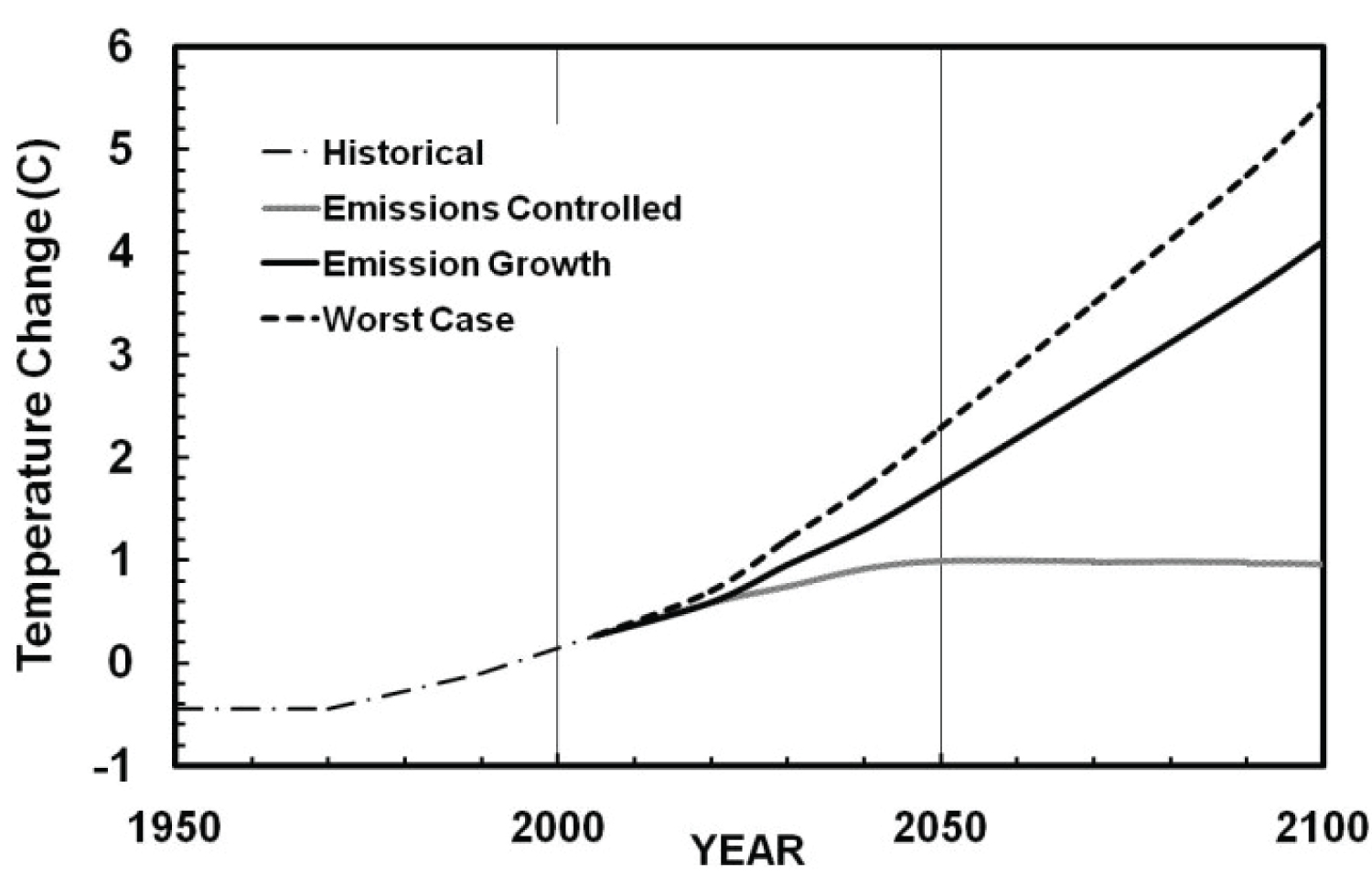
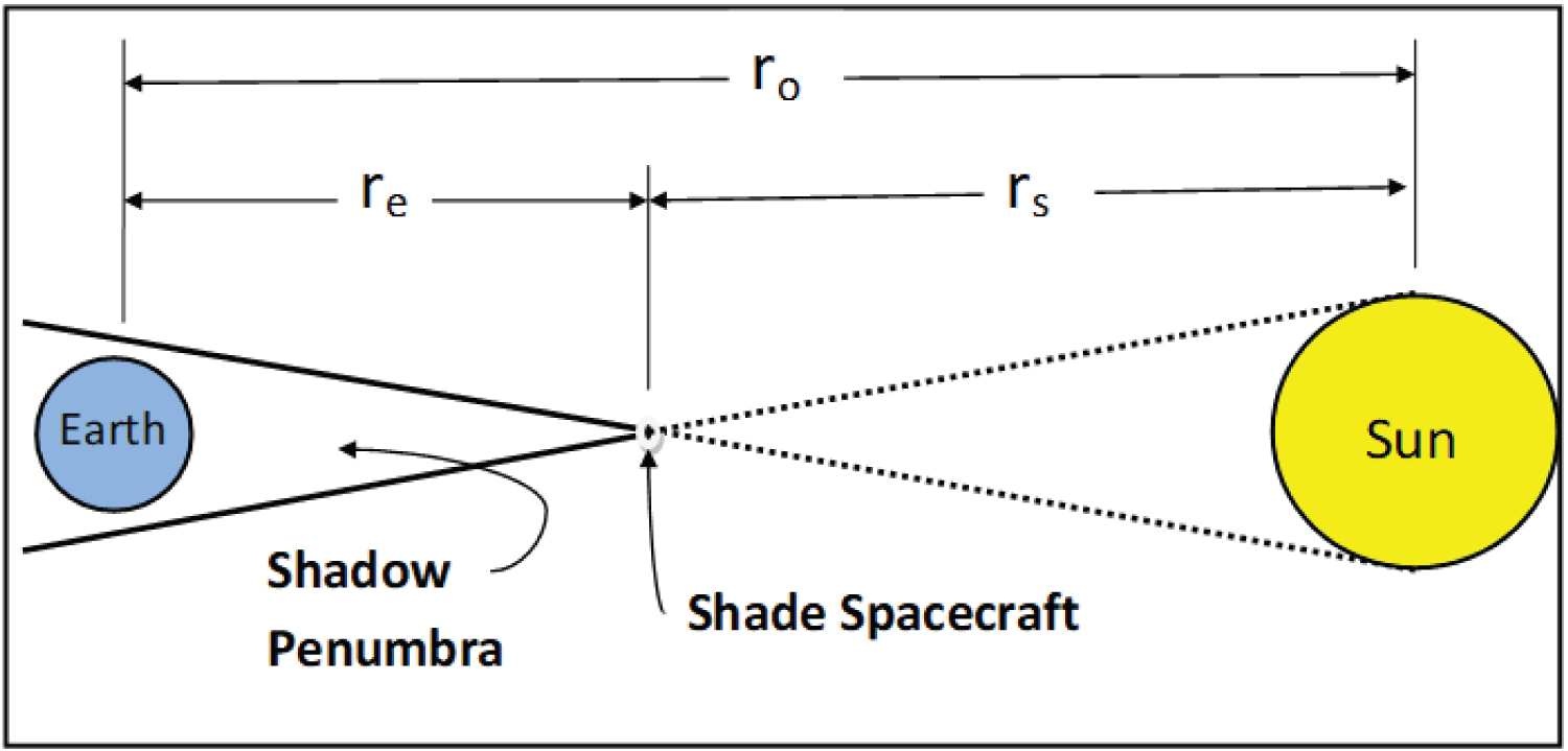
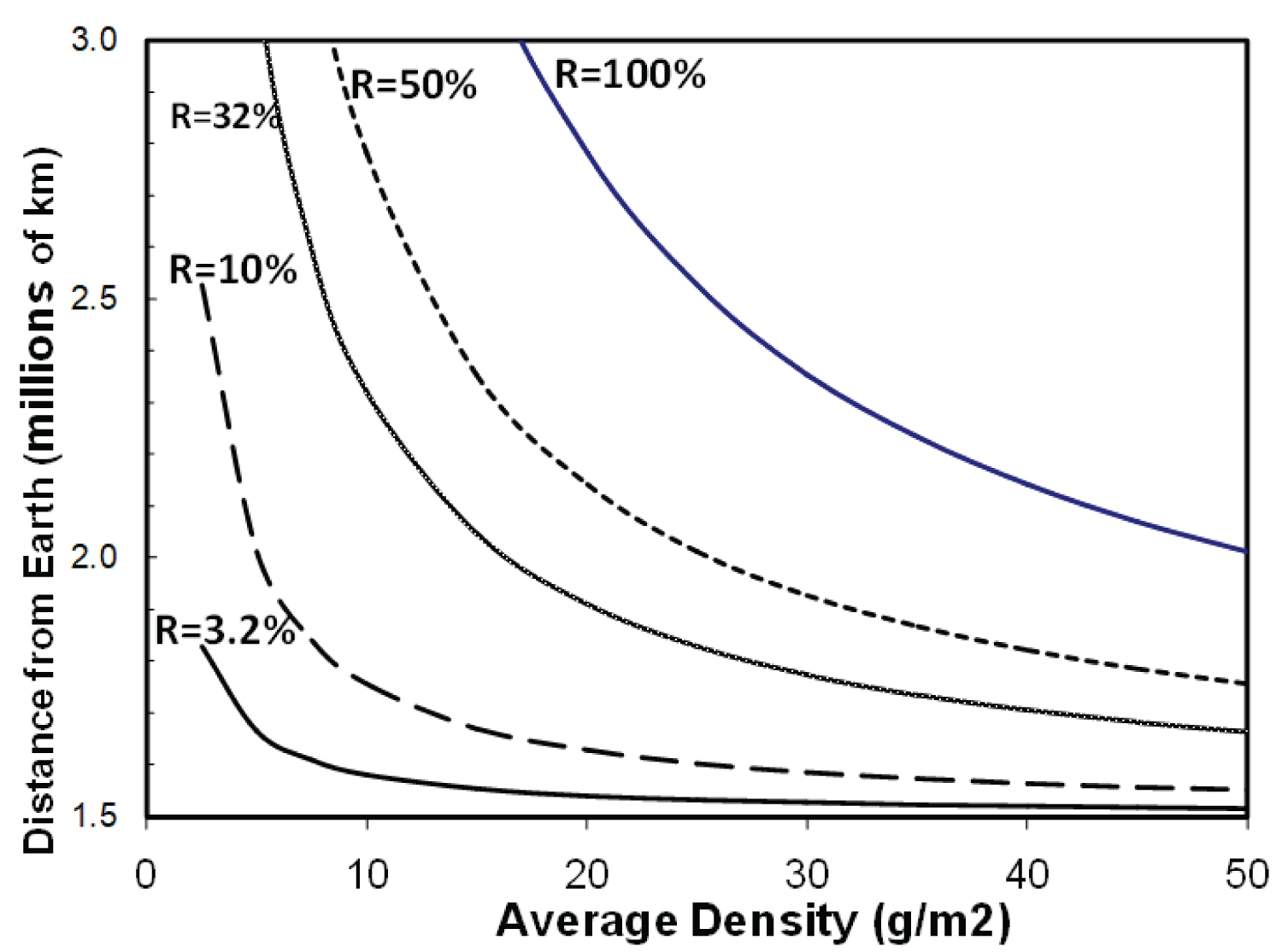
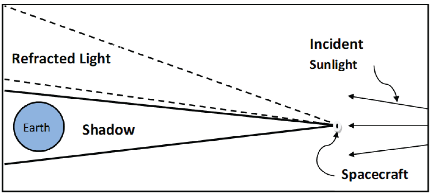
Figure 4: Transparent shade (Vertical scale...
Transparent shade (Vertical scale expanded by ~20x); Light is refracted rather than absorbed or reflected to minimize photon pressure.
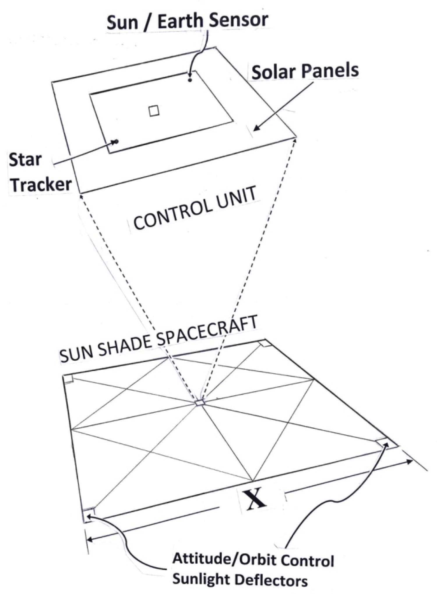
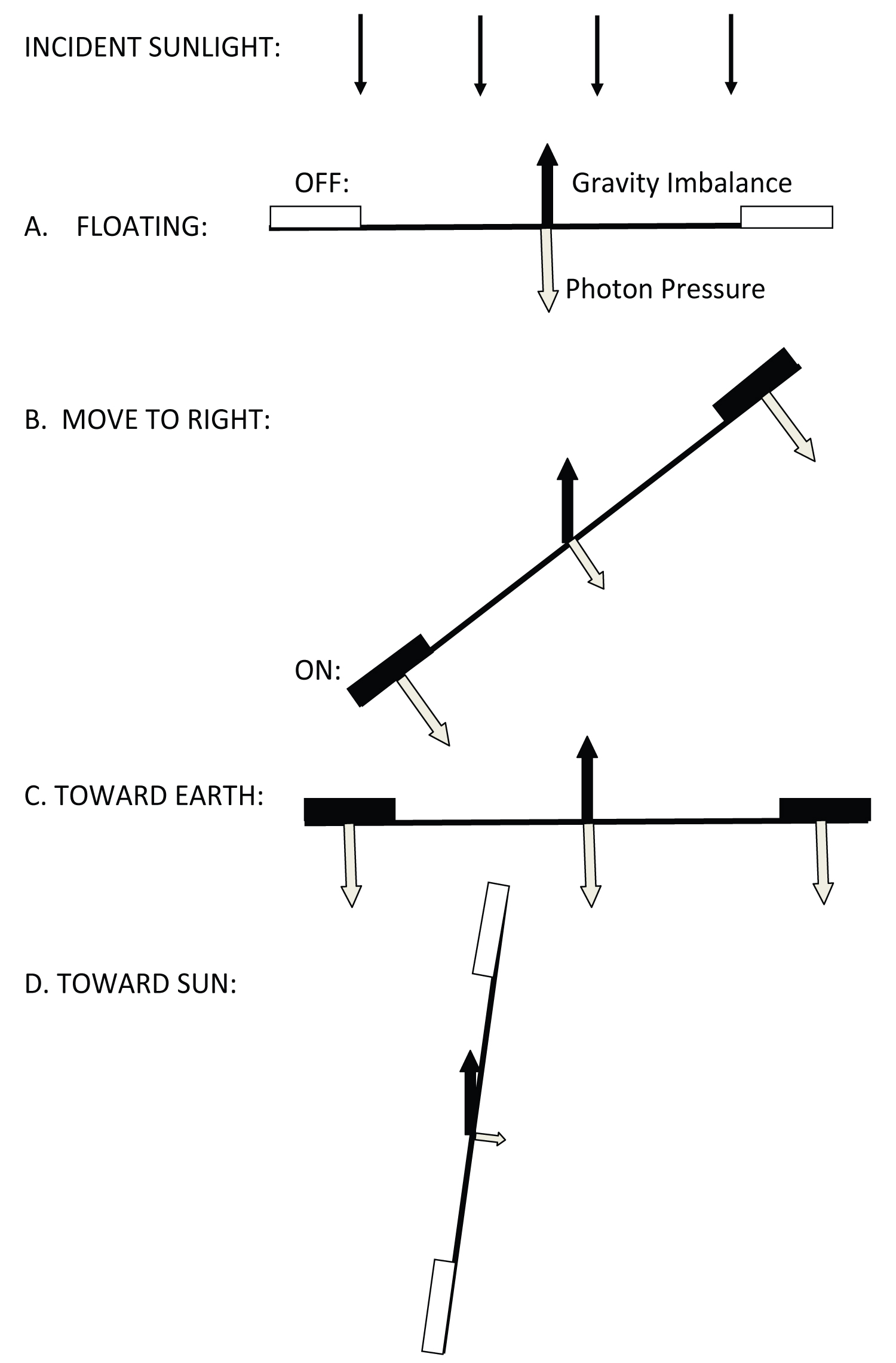
Figure 6: Attitude and velocity control using....
Attitude and velocity control using gravity and reflected sunlight: Velocity changes can be introduced in any direction by changing the balance between photon pressure and the fixed gravity bias.
References
- (2014) IPCC fifth assessment report (AR5).
- (2019) IPCC special report on the impacts of global warming of 1.5 °C.
- Muntean M, Guizzardi D, Schaaf E, Crippa M, Solazzo E, et al. (2018) Fossil CO2 emissions of all world countries - 2018 Report. EUR 29433 EN, Publications Office of the European Union, Luxembourg.
- (2016) The paris agreement. UNFCCC.
- Stavins RN, Stowe RC (2016) The Paris agreement and beyond: International climate change policy post-2020. Harvard Project on Climate Agreements, Cambridge Mass, Middlesex.
- Keith D (2017) Toward a responsible solar geoengineering research program. Issues in Science and Technology, 33.
- Teller E, Wood L, Hyde R (1997) Global warming and ice ages: I prospects for physics-based modulation of global change. UCRL-JC-128715, Lawrence Livermore National Laboratory, USA, 29.
- Seifritz W (1989) Mirrors to halt global warming? Nature-Scientific Correspondence, 340.
- Kosugi T (2010) Role of sunshades in space as a climate control option. Acta Astronaut 67: 241-253.
- Eddy JA (1976) The maunder minimum. Science, 192.
- Scafetta N, Willson RC (2014) ACRIM total solar irradiance satellite composite validation versus TSI proxy models. Astrophysics and Space Science, 350.
- Early JT (1989) Space-based solar shield to offset greenhouse effect. Journal of the British Interplanetary Society 42: 567-569.
- McInnes CR (2002) Minimum mass solar shield for terrestrial climate control. Journal of the British Interplanetary Society 55: 307-311.
- Angel R (2006) Feasibility of cooling the earth with a cloud of small spacecraft near the inner Lagrange Point (L1). Proceedings of the National Academy of Sciences of the USA 103: 17184-17189.
- (2011) Climate engineering: Technical status, future directions and potential responses. USA Government Accounting Office (GAO), Center for Science, Technology and Engineering.
- Keith D, Morton O, Shyur Y, Worden P, Wordsworth R (2020) Reflections on a meeting about space-based solar geoengineering. Harvard's solar Geoengineering Research Group, USA.
- Friedman LD, Sohn RL, Moore JW (1972) Navigation requirements for advanced deep space missions. Institute of Navigation National Space Meeting, USA 19: 266-280.
- Stanton RH, Ohtakay H, Miller JA, Voge CC (1975) Demonstrating optical navigation measurements on mariner 10. AIAA 13th Aerospace Sciences Meeting, 75-86.
- Stanton RH, Alexander JW, Dennison EW, Glavich TA, Hoveland LF (1987) Optical tracking using charge coupled devices. Optical Engineering 26: 930-938.
- Mori (2010) Small solar power sail demonstrator ‘IKAROS' successful attitude control by liquid crystal device. Japan Aerospace Exploration Agency, Japan.
- Zheng F, Chen M, He J (2012) Analyses of a huge space shield to weaken the global warming. AIAA SPACE 2012 Conference and Exposition.
- He J, Zheng F (2017) Structural feasibility and orbital stability of a proposed huge space shield for mitigating global warming. Advances in Mechanical Engineering 9: 1-8.
- Berger E (2018) The falcon heavy is an absurdly low-cost heavy lift rocket. Ars Technica.
- Mendell W (1985) Lunar bases and space activities of the 21st Lunar and Planetary Institute, Houston, USA.
- Augustine NR, Austin WM, Chyba C, Kennel CG, Bejmuk BI, et al. (2009) Seeking a human spaceflight program worthy of a great nation. Review of US Human Spaceflight Plans Committee.
- Watson-Morgan L, Chavers G, Connolly J, Dwyer-Cianciolo A, Garcia CP, et al. (2020) NASA's human lunar landing strategy. 71st International Astronautical Congress, IAC-20-B3.1.11.58416.
- Andrews D (2020) VIPER: Pathfinder in-situ resource utilization. 71st International Astronautical Congress, IAC-20-2A-1.
- Mankins JC, Mankins WM (2020) Biological Requirements for a Sustainable Settlement on Earth's Moon. 71st International Astronautical Congress, IAC-20-A1.7.5.
- Sanders G (2019) NASA lunar ISRU strategy, what next for space utilization? Workshop, Luxembourg.
- Pereira A, Vaccaro D, Chung S, Rajagopalan R, Biddington B, et al. (2020) Artemis: Perspectives from Australia, Japan, South Korea and India. 71st International Astronautical Congress, IAC-20-D4.2.9x59642.
- McNab IR (2003) Launch to space with an electromagnetic railgun. IEEE Trans Magnetics 39: 295-304.
- Doyle MR, Samuel DJ, Conway T, Klimowski RR (1994) Electromagnetic aircraft launch system. IEEE Trans Magnetics 31: 258.
- Wright MR, Kuznetsov SB, Kloesel KJ (2011) A lunar electromagnetic launch system for in-situ resource utilization. IEE Trans on Plasma Science 39: 521-528.
- Randers J, Goluke U (2020) An earth system model shows self-sustained thawing of permafrost even if all man-made GHG emissions stop in 2020. Sci Rep 10: 18456.
Author Details
Richard H Stanton*
Nikolaev Institute of Inorganic Chemistry, SB RAS, Novosibirsk, Russia
Corresponding author
Richard H Stanton, Jet Propulsion Laboratory (retired), Big Bear City, CA 92314, USA, E-mail: rhstanton@gmail.com
Accepted: May 13, 2021 | Published Online: May 15, 2021
Citation: Stanton RH (2021) Controlling Climate Change from Space-Initial Steps. Int J Astronaut Aeronautical Eng 6:051.
Copyright: © 2021 Stanton RH. This is an open-access article distributed under the terms of the Creative Commons Attribution License, which permits unrestricted use, distribution, and reproduction in any medium, provided the original author and source are credited.
Abstract
Reducing the solar irradiance falling on Earth using structures at the Sun-Earth inner Lagrange point (L1) could decrease global warming even if all other methods prove inadequate. This solution is certainly feasible, but its scale requires long-term planning and investment. This paper explores ideas for building a swarm of spacecraft shades to provide the required sunlight reduction. Each member of this swarm autonomously measures and controls its orbit, ensuring durability of the swarm over many decades. Two possible implementations are discussed: A "small" swarm that could be launched from Earth, and a longer-term approach using material from the Moon (or asteroids), needed if greater reductions of solar irradiance are required.
Keywords
Small sunshades at L1, Control of climate change, Spacecraft swarm, Autonomous station-keeping, Research and development program
Introduction
Motivation
Current projections from the Intergovernmental Panel on Climate Change (IPCC) [1,2] suggest that the world is likely to continue warming through the rest of this century, principally because of the global use of fossil fuels. The degree of warming predicted depends strongly on the amount of greenhouse gas (GHG) released into the atmosphere (Figure 1). If the use of fossil fuels can be restricted sufficiently, the warming predicted should be relatively mild (lower curve). The more extreme scenarios resulting from less control (upper curves) predict warming that could do serious harm to both the environment and humanity. Many countries have made progress reducing emissions [3], but much remains to be done. The Paris Agreement and subsequent accords [4,5] document this worldwide effort of GHG control.
Many scientists today believe that even the complete cessation of GHG emissions may not produce adequate cooling of Earth. Because of a number of factors "there is a small but significant chance that the world will continue to warm for more than a century after emissions stop [6]." This possibility has led to the pursuit of other means of cooling Earth in addition to controlling GHG emissions. These additional means include (1) Removing CO2 from the atmosphere, (2) Increasing the reflectance of the Earth atmosphere, clouds or surface, and (3) Shading some incident sunlight in space before it reaches Earth. Only the last of these ideas is addressed here, an approach that avoids some of the risks and uncertainties of other methods.
How much shading might be needed?
Some early calculations have suggested that reductions in Total Solar Irradiance (TSI) as much as 1% [7] up to 3.5% [8] might be needed if global warming continues unabated. A much smaller figure (0.8 W/m2 = 0.06%) has been proposed by Kosugi [9] based on modeled scenarios of future emissions. A shading of this level beginning in the year 2075 and lasting a century could compensate for his modeled GHG emission profile.
The efficacy of such a small TSI reduction is also suggested by historical data, including the cooling experienced in Europe in the late 17th century Maunder Little Ice Age. A decrease of 0.1% in solar irradiance was likely an important contributor to the cold winters and significant crop failures of this time. This cooling has been correlated with the almost complete absence of sunspots during this period [10]. Thirty-five years of satellite radiometer data have shown that the variation in solar irradiance between periods of high and low sunspot activity is on the order of 0.1% [11].
All of this suggests that any system designed to shade sunlight from Earth should be capable of providing a reduction in TSI over a range of at least 0.06% to 3%, a factor of 50. The approach suggested here provides this level of scalability.
Shade location
One can imagine shade structures orbiting either close to Earth or fixed on the Earth-Sun line at L1. In Earth orbit, a 0.06% TSI reduction would require an area Ae = 0.0006 π (6371)2 = 76,500 km2. This area would have to be increased to compensate for the fact that each shade casts a shadow on Earth for only part of its orbit. For circular orbits the required shade area would need to be increased by more than a factor of two, but a smaller factor should be possible with a well-designed elliptical orbit.
The geometry at L1 is illustrated in Figure 2. In this case the shade is located 1.6 × 10⁶ km from Earth, a value biased somewhat toward the sun to offset the effect of photon pressure. As can be seen from the figure, a small shade casts a penumbral shadow on Earth of diameter.
d = ds (re/rs), (1)
re is the distance from the shade to Earth, rs the distance from the shade to the Sun and ds the diameter of the Sun. For re = 1.6 × 10⁶ km, d = 14,900 km. Because this more than covers Earth (de = 12,742 km) the shade is only de2/d2 = 73% efficient. More generally, the shade area required for a 0.06% TSI reduction at L1 is
AL1 = Ae (rs/ro)2 (d/de)2 (2)
ro being the mean distance between the Earth and Sun. The first factor accounts for sunlight being slightly more intense at L1 than in Earth orbit. For the case under consideration (re = 1.6 × 10⁶ km, 0.06% TSI reduction), AL1 = 102,000 km2. This coverage could be achieved using a single square shade ~ 320 km on a side.
Benefits of shades at L1
In addition to being the only location in the solar system where an object continuously casts its shadow on Earth, there are other significant advantages at L1:
1. Shades at L1 pose no risk to the Earth atmosphere or environment. If a shade produces undesirable effects, it can easily be moved to an orbit that does not cast its shadow on Earth,
2. All changes in solar irradiance would be imperceptible to humans. There would be no visible reflections lighting up the day or night sky,
3. Shading would be generally uniform over the entire sunlit hemisphere, ignoring the small effects of limb darkening and sunspot images,
4. Shading will cool Earth whether warming is caused by excess GHG; Heat generated by cars, planes and nuclear power plants; or variability in the Sun itself.
A way forward
It is clear that even a small reduction of the TSI reaching Earth requires a huge shade area, whether shading is done from Earth orbit or L1. Starting with a discussion of the general problem of locating shades at L1, a conceptual spacecraft configuration is proposed, including a method for autonomous station-keeping to insure long-term survival of the shade spacecraft. Two separate implementations are considered to address the range of shading that might be needed. Recognizing the huge challenges facing either option, a number of near-term research and development activities are proposed that could bring this concept closer to reality.
Sunshades at L1
Effect of photon pressure
Seifritz [8] proposed reflecting 3.5% of the Sun's energy at L1 with a metallic shade covering an area of 4.5 × 10⁶ km2. Early [12] showed that pressure from sunlight falling on the shade can be significant for the low-density shade structures envisioned. Fortunately, this force can be counterbalanced by moving the shade closer to the Sun than the nominal L1 point, producing a gravity imbalance that offsets the force of photons pushing the shade earthward.
With no radiation pressure, the gravity balance keeping the shade orbiting with the same angular frequency as Earth (ωe) can be written:
mcrsωe2 = GmcMs/rs2 - GmcMe/re2 (3)
Where, Ms, Me and mc are the masses of the Sun, Earth and spacecraft, and G the gravitational constant. The photon force adds a term pushing toward Earth,
rsωe2 = GMs/rs2 - GMe/re2 - CeR(ro/rs)2 (A/mc) (4)
Where Ce = 9.08 × 10⁻⁶ N/m2 (the force of reflected sunlight at Earth distance), A is the shade area, R = fr + 0.5fa (fr is the fraction of incident light reflected and fa the fraction absorbed).
Equation (4) can be solved for re, the distance of the shade from Earth as a function of R and average spacecraft density (mc/A). For relatively dense scientific spacecraft, the effect of photon pressure is negligible. But for low-density shade spacecraft it can be very significant. Figure 3 shows that the orbit displacement required can be several hundred thousand kilometers, depending on the mass density and optical reflectivity of the shade.
Early [12] also proposed reducing photon pressure by making the shade a transparent Fresnel lens to deflect incident sunlight (Figure 4). In addition to lowering photon pressure on the structure, this design could be used to focus additional light on Earth should warming ever be needed. In that case each spacecraft would be moved so its shadow completely missed Earth while the refracted sunlight projected onto it. Subsequent authors proposed other light-deflecting materials to lower shade mass [7,13,14].
Potential show-stopper
In 2011 the United States Government Accountability Office (GAO) Center for Science, Technology and Engineering evaluated many of the proposals for solar radiation management, ranging from injecting material into the atmosphere to placing huge structures at L1 [15]. Ideas in the latter category were rejected with a single sentence: "[These] technologies are impractical at this time because they require manufacturing capabilities in space." One should also add that the difficulty of controlling such huge lightweight structures could be daunting-we simply have no experience with controlling thousand-kilometer light weight structures in space. A recent meeting of concerned experts [16] concluded that little has changed in this picture in the last decade.
New Approach
Swarm of smaller shades
Rather than using structures hundreds or thousands of kilometers across, the required shading could be provided by a swarm of much smaller shades. An example in this direction was Angel's proposal to use 16 trillion shades, each 0.6 m in diameter [14]. This may have been optimal in some sense, but certainly many other configurations are possible. A more general approach treats the size of individual spacecraft as the adjustable parameter with the number needed determined by the total shade area required. The size ultimately selected would reflect the requirements and constraints of all elements in the design, including the launch system.
Breaking the shade area into many smaller pieces has important advantages:
1. The development and testing program can include flying full-size test models to address design issues well in advance of swarm deployment,
2. The total shade area will gradually increase as individual spacecraft are added, enabling fine tuning of the climate effects on Earth,
3. If individual shades are small enough, it may be possible to avoid any in-space assembly,
4. The system vulnerability to individual failures or to malicious attacks is greatly reduced.
Shade spacecraft concept
A conceptual design for a shade spacecraft is shown in Figure 5. Each consists of a large structure supporting the transparent panels that deflect incident sunlight by a small angle. A square shape is illustrated although the final shape of the spacecraft and the details of the support structure are undefined at this point. The overall size (marked "X" in the figure) is the key parameter that will be determined by detailed design tradeoffs and analyses of all relevant elements.
Sunlight modulators shown at each corner are used for attitude and orbit control. All solar panels, electronics, optical sensors, and antennas could be integrated into the smaller control unit at the center of the structure. The small size and mass of this module should allow it to be fabricated and tested as a unit before being integrated, possibly in orbit, with the much larger shade structure. Each spacecraft will autonomously control its attitude and orbit (next paragraphs). The capability of monitoring and commanding individual members of the swarm from Earth will be available but not required during nominal operations.
Autonomous station-keeping
Navigating optically: The unstable equilibrium at L1 implies that orbit control (station-keeping) is required to keep any object in orbit for an extended period of time. For a scientific spacecraft, orbit maintenance normally is accomplished using radio tracking and commanding for needed orbit corrections. A swarm of millions or billions of shades might be difficult to control in this manner. If each spacecraft autonomously maintains its orbit relative to L1, operational complexity and risk are greatly reduced.
To accomplish this, three essential onboard functions are needed: First, position and velocity must be measured relative to L1. Second, onboard algorithms are needed to translate these measurements into orbit-correction maneuvers and determine when these should be executed. Third, the control system must have the ability to autonomously execute maneuvers of the required magnitude in any direction. The following paragraphs describe how the first and third functions can be performed using only optical measurements and reflected sunlight. The onboard intelligence required for the second function is considered achievable with current technology.
Onboard orbit measurement: The continuous measurement of the spacecraft orbit relative to L1 can be accomplished using “optical navigation” techniques developed for the Voyager flyby of Jupiter in 1979 [17]. This navigation method relies on accurately measuring the direction to a target body relative to background stars [18]. The advent of solid-state imaging arrays that replaced the vidicons used on Voyager has dramatically increased the accuracy of these measurements [19].
How could this technique be used for station-keeping at L1? First, one measures the apparent size of Earth and its position relative to known background stars. Earth's apparent diameter from 1.6 × 10⁶ km is 0.456° = 1642 arcsec. Measuring center coordinates to 1/1000 of the diameter of this image and simultaneously measuring coordinates of identified background stars will accurately determine the spacecraft-to-Earth direction. The same camera can be used to measure Earth's apparent diameter to one part in 10,000. Since the direction from Earth to L1 is always known on the spacecraft, the (x,y) coordinates of the spacecraft relative to L1 can be calculated to better than 15 km (2 arcsec at 1.6 × 10⁶ km) and the range to 160 km (1.6 × 10⁶/10000). With all three coordinates continuously measured with respect to the desired orbit, the onboard executive has all it needs to decide when station-keeping maneuvers are needed and calculate their magnitude and direction.
Attitude and orbit control: Each spacecraft can control its attitude and orbit using a combination of gravity imbalance and controlled sunlight reflection. Unlike most “solar sail” missions, the existence of the gravity imbalance used to counteract photon pressure provides the ability to sail (tack) toward the sun as needed. This concept is illustrated in Figure 6. The rectangular boxes at the ends of the shade represent electro-optic devices that reflect light when powered (ON = solid black in figure). Similar technology has been demonstrated during the flight of IKAROS, using only reflected sunlight to control a rotating 20m solar sail [20]. Figure 6A illustrates the nominal orientation that is maintained in three axes based on star sensor data. Modern star sensors can autonomously identify star fields and provide attitude information for every possible orientation. Rotation about the spin axis (nominally pointed toward the Sun) must also be controlled, requiring additional reflectors (not shown). Also not shown are any reflectors needed to escape from an edge-to-sun orientation.
If the onboard executive determines that a velocity correction is needed, Figure 6B to Figure 6D illustrate how motion toward the side, toward Earth or toward the Sun can be introduced. The main requirement is that the actuators have sufficient authority to recover from any worst-case motion or orientation.
Collision avoidance
One might think that orbiting millions or billions of spacecraft in the relatively small area constrained to cast a shadow on Earth would risk collisions. But as is clear in Figure 3, the individual spacecraft can be distributed over radial distances from Earth over a range of 100,000 km or more by adjusting reflectivity and mass density. Spreading the spacecraft out in this way gives the cluster on the order of 2 trillion cubic kilometers in which to roam, greatly reducing any chance of collision.
Two Implementations
Minimal system
First consider a swarm of shades launched from Earth. This approach has the significant advantage that everything could be manufactured on Earth using existing ground and launch technology. In this way Kosugi's 0.06% shading requirement could be met by the year 2075. Each sun shade spacecraft could be deployable similar to the design proposed by Zheng, et al. [21,22]. Given current capability, a SpaceX Falcon Heavy launch vehicle could lift two such spacecraft to low earth orbit (LEO) with a single launch. Two 1.4 km-diameter shades would provide 3.08 km2 shade area per launch. A shading of 0.06% would then be achieved with 102,000/3.08 = 33,000 launches, costing some $ 5T in today's prices [23].
This cost estimate must be considered a lower limit because each shade still must be lifted from LEO to L1. Moreover, 0.06% shading is almost certainly a lower bound of what might be needed. Despite these limitations, this case illustrates what might be possible in the next 50 years using only resources available on Earth.
One percent system
Many estimates call for deflecting a much larger portion of sunlight than 0.06%. In the following discussion a 1% shading level is assumed. The one fact that seems inescapable for systems of this magnitude is that most of the material needed cannot reasonably be launched from Earth.
Mass required: A 1% reduction in TSI requires a total shade area 16.6 times larger than for the 0.06% system. Assuming a density of 20 g/m2 the total mass will be 3.41 × 10¹⁰ kg. Launching this much material to LEO would require 534,000 Falcon Heavy launches. Even if the world could afford this level of launch activity, the environmental impact might well prove unacceptable.
Material from the moon: The number of launches from Earth could be dramatically reduced using material from the Moon (or asteroids) for most shade components. The two major costs associated with reaching L1 are dramatically reduced by this approach: First, it would no longer be necessary to launch massive rockets to carry relatively small payloads through the Earth atmosphere. The Falcon Heavy weighs over 1.42 × 10⁶ kg at liftoff, 22 times the maximum payload it can deliver to LEO. In contrast, spacecraft could be launched electromagnetically from the airless Moon with very little structural overhead. Second, reaching interplanetary space (L1) requires 22 times less energy from the Moon than from Earth (2.8 vs. 62.5 MJ/kg). These two factors of 22 make heavy missions launched from Earth to interplanetary space difficult and costly, whether they are swarms of sunshades or human missions to the planets.
Of course, major developments must occur before any manufacturing and launch from the Moon can be achieved. An important lesson from the Apollo program is that strong and sustained popular support can achieve miracles, even using 1960s technology! This support was sustained all during the Apollo development, but faded rapidly once the landings were accomplished. There was no lack of ideas for future lunar exploration [24], simply an absence of political will to proceed. As the report of the Augustine committee [25] points out:
"Planning a human spaceflight program should start with agreement about the goals to be accomplished by that program-that is, agreement about its raison d'etre, not about which space object to visit. Too often in the past, planning the human spaceflight program has begun with 'where' rather than 'why'."
Perhaps the goal of "saving Earth from climate change" will motivate the lunar exploration and technology development that we know are possible.
Research and Development Program
The two implementations outlined above require spacecraft designs that are different. An Earth-launched system would need to fit within existing or future launch vehicle shrouds. Spacecraft designed to be launched electromagnetically from the Moon might well be configured very differently. But both approaches could make use of deployable structures to avoid assembly in space, implement autonomous orbit control using reflected sunlight and both would need similar membrane material. These commonalities suggest that a near-term design, test and flight development program could significantly accelerate the technology required for swarm deployment, whether that deployment is from Earth or the lunar surface.
Transparent panel material
Several ideas have been proposed for the light-weight membranes needed to refract incident sunlight away from Earth. These include 10 µ thick glass panels using Fresnel prisms for deflection [12], diaphanous metallic mesh gratings [7], and a layered silicon nitride structure to diffract sunlight with low reflectivity [14]. The fabrication and testing of these and other candidates should be a near-term priority. Which of these materials can be successfully attached to deployable structures and survive decades in space after deployment?
Electro-optic sunlight reflector
The capability for electrically controlling the intensity, and possibly direction, of reflected sunlight may well be a key for long-term orbit and attitude control. Devices appropriate for this application should be developed and their performance and durability measured during long exposure to the environments expected at L1.
Deployable structures
A number of initial designs and some flight tests have been performed addressing the general problem of light-weight deployable space structures [20-22]. Extending these efforts to the detailed design, fabrication and testing of a large deployable structure with appropriate membrane material would be a tremendous step forward.
Flight tests
One of the most important advantages of breaking 1000 km shades into smaller units is the ability to test in flight all aspects of the design prior to any commitment to deploy the full-size system. Initial flights could be conducted in LEO to evaluate deployment designs and test the ruggedness of candidate membranes. Once these flights are successful, larger more ambitious designs might be pursued. Transporting various test models to L1 should be straightforward, enabling extended testing that includes all aspects of autonomous attitude and orbit control. The durability of all components of the design in the L1 environment would also be evaluated.
Lunar mining, fabrication and launch
At present humanity is a long way from being able to mine needed material on the Moon (or asteroids) and convert this material into spacecraft. The lunar surface provides abundant sources of aluminum and glass, likely to be major components of the shades. In 2017 NASA announced the Artemis program, an ambitious plan to return astronauts to the surface of the Moon as early as 2024 [26]. Further exploration includes measuring water ice deposits buried in permanently shaded craters [27] and establishing a permanent base near the lunar South Pole [28]. International interest and participation in lunar exploration have grown in recent years, inspired in part by NASA's aggressive plans for In-Situ Resource Utilization [29] and the apparent economic viability of extracting materials such as Rare Earth Metals from the Moon [30].
Electromagnetic launchers have fully demonstrated the ability to accelerate small payloads to speeds of several kilometers per second [31]. Systems been developed to replace steam-powered catapults for aircraft takeoff [32]. Possible configurations for launching payloads from the lunar surface to lunar orbit have been developed [33]. Designs for launching larger payloads from the Moon will need to be developed.
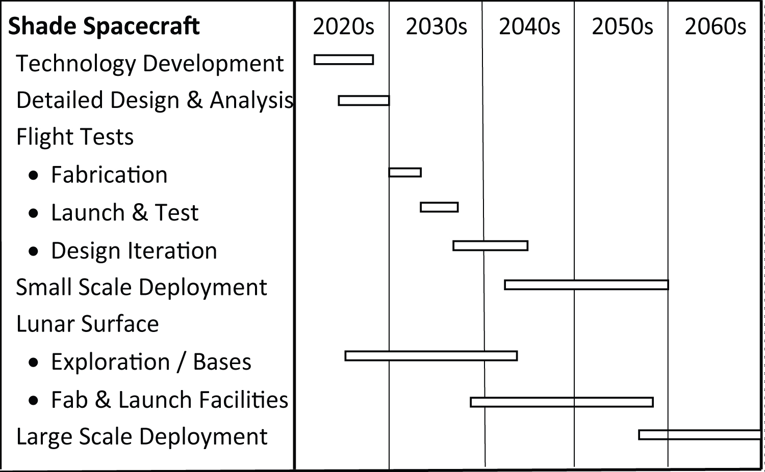
Strawman schedule
It is anyone's guess as to if or when these steps will be taken. Figure 7 presents one guess of when they could happen, given sufficient motivation.
Summary
If eliminating anthropogenic GHG emission does not reverse global warming [34], additional steps must be taken. Blocking a small portion of incoming sunlight from space can safely provide the needed cooling. Specifics of the shading approach described here can be summarized as follows:
1. L1 is the ideal location for shade structures to reduce the solar irradiance on Earth. This is the only location in the solar system where a spacecraft can continuously cast a shadow on Earth.
2. Photon pressure pushing a spacecraft toward Earth at L1 can be offset by a constant gravity imbalance. This imbalance also makes it possible to maintain orbit control using only reflected sunlight.
3. A huge area of sunlight must be intercepted whether the shading structures are located at L1 or in Earth orbit. This is the fundamental challange that must be addressed.
4. Shading Earth using a "swarm" of small spacecraft has significant advantages compared to flying shade structures hundreds or thousands of kilometers across.
5. Deployment of limited shading is possible using spacecraft built and launched from Earth. This approach will be constrained by how many thousands of heavy launches are feasible. More substantial reductions in solar irradiance seem likely only by using material available in space, such as from the Moon.
There is much that can and should be done in the next years to make cooling of Earth from space a realistic option. While there is little doubt that success could be achieved, it is less certain that humanity will respond soon enough should the warming of our planet continue.
Acknowledgement
The author thanks Dr. Yomay Shyur for her very helpful comments and suggestions on issues important to the solar geoengineering community. He is indebted to Darle Tilly for her important editorial suggestions.