
International Journal of Magnetics and Electromagnetism
(ISSN: 2631-5068)
Volume 5, Issue 1
Research Article
DOI: 10.35840/2631-5068/6519

Article Formats
Electrodynamic Concentration of Non-ferrous Metallic Particles in the Moving Gas-powder Stream: Mathematical Modeling and Analysis
Table of Content
Figures
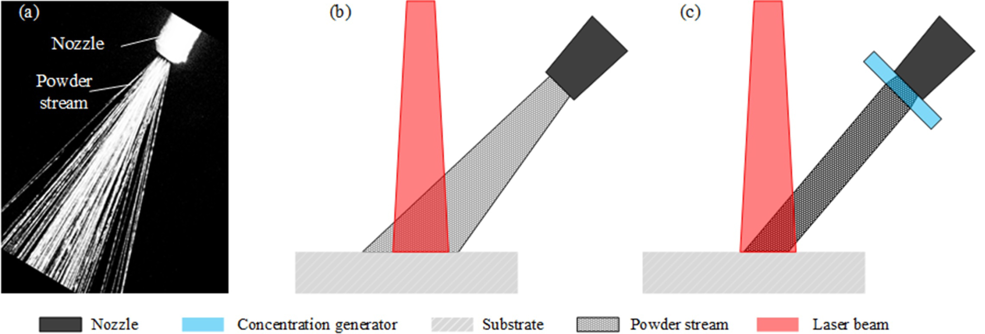
Figure 1: Powder stream of a lateral laser powder-fed...
Powder stream of a lateral laser powder-fed process a) Powder stream image; b) Schematic of the divergent powder stream and laser beam; c) Schematic of the concentrated powder stream and laser beam.
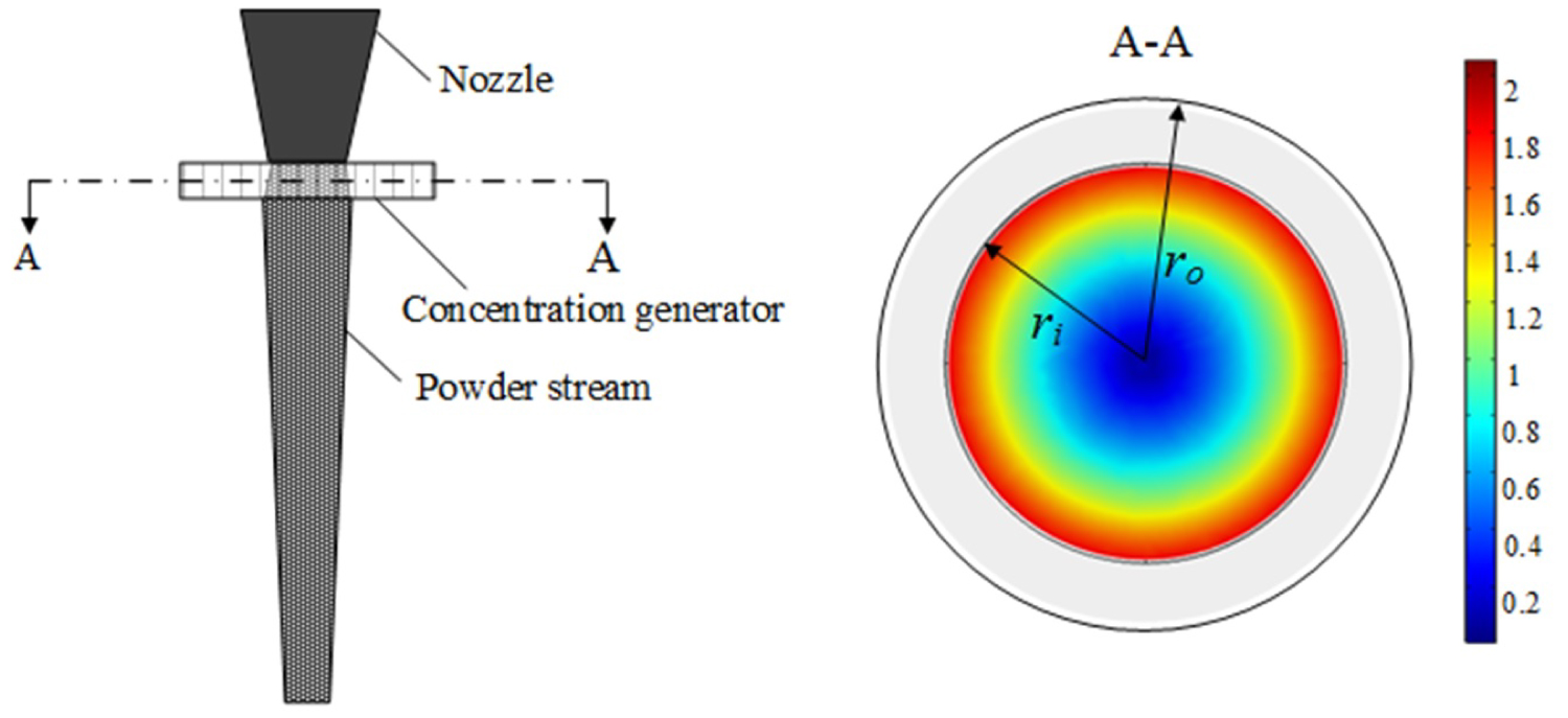
Figure 2: Schematic diagram for the proposed...
Schematic diagram for the proposed magnetic concentration approach. The magnitude of the field intensity in the transverse cross-section were marked with the color bar (the scale bar shows the relative values), decreasing from the circumferential region towards to the center region from red color to blue color. Inner radius ri and outer radius .
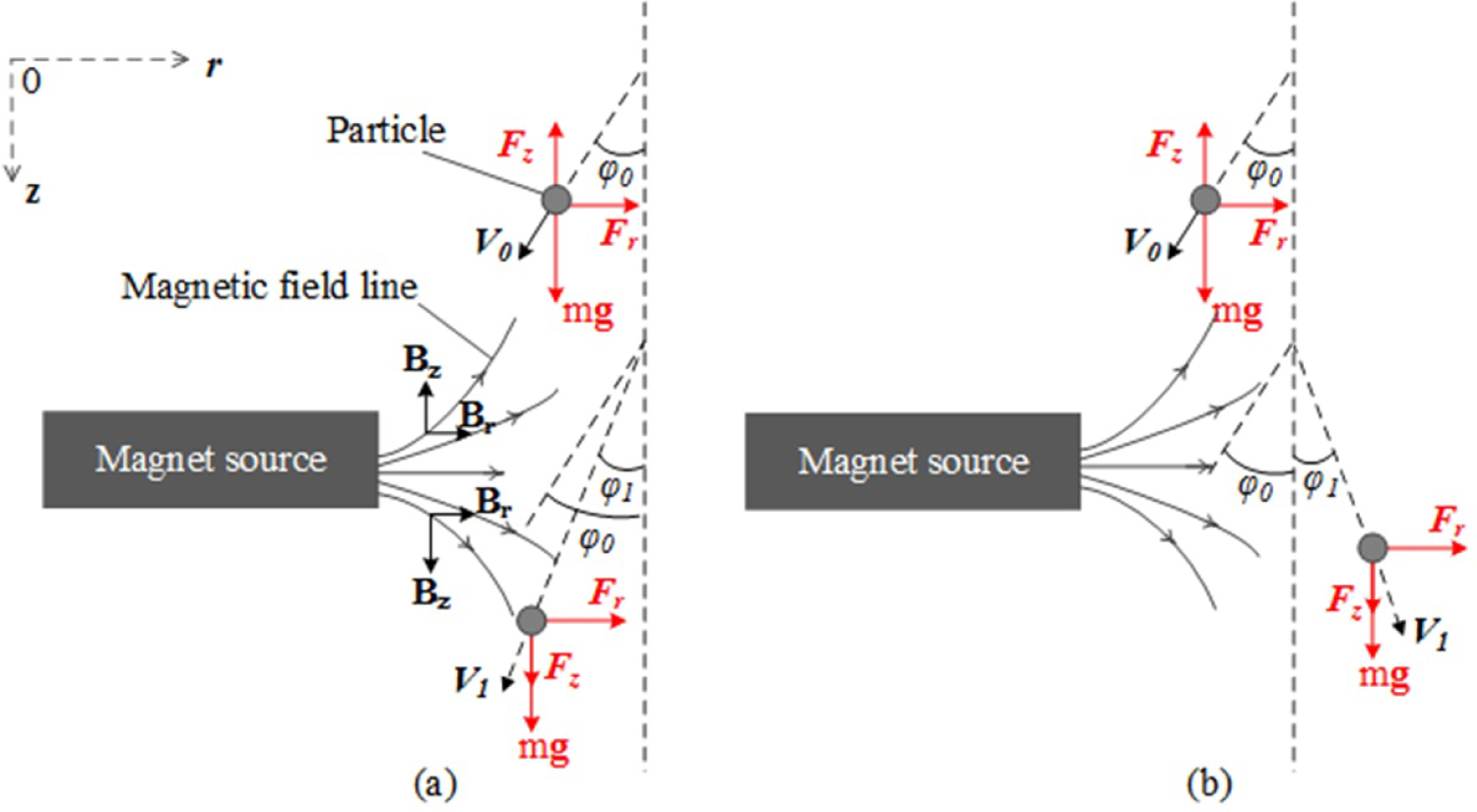
Figure 3: Force analysis of the moving particle...
Force analysis of the moving particle in the longitudinal cross-section when the particle travels through the proposed concentration generator. a) Radial velocity of the particle keeps centrifugal direction; b) Radial velocity of the particle changes to centripetal direction. Initial velocity and divergence angle . Final velocity V1 and divergence angle .
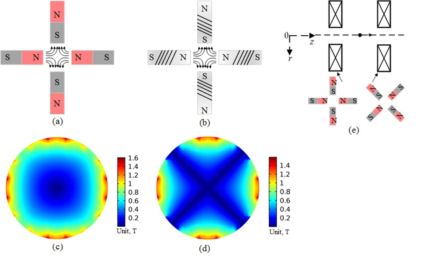
Figure 4: Schematic illustration of the...
Schematic illustration of the quadrupole-based concentration generator. a) Permanent-magnet-based quadrupoles; b) Electro-magnet-based quadrupoles; c) and d) Represent the norm and radial (Br) magnetic field intensity in the transverse cross-section quadrupoles, respectively. Composed by neodymium N52 magnets with residual magnetic intensity ; e) Doublet-quadrupoles arrangement.
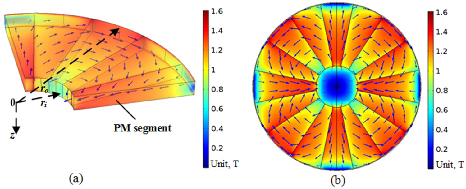
Figure 5: Schematic illustration of the proposed...
Schematic illustration of the proposed magnetic concentration generator with Halbach PM configuration. a) 3D view of the quarter segment and b) Magnetic field intensity norm for the inner region ( ) of the Halbach PMQs array. Composed by neodymium N52 magnets with residual magnetic intensity . The blue arrows represent the magnetic field direction.
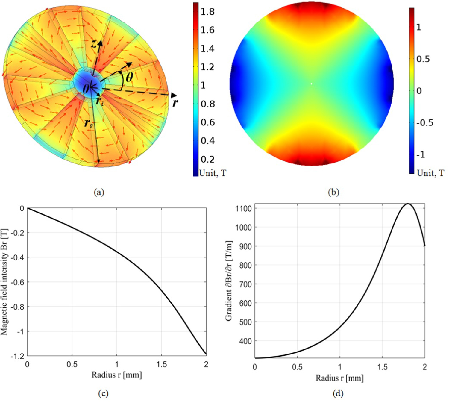
Figure 6: Simulated magnetic field of the concentration...
Simulated magnetic field of the concentration generator with Halbach-PMQs configuration. a) Magnetization configuration 3D view with magnetic field intensity norm ( T ), the red arrows represent the magnetic field direction; b) Magnetic field intensity Br 2D distribution in the transverse cross-section (); c) Magnetic field intensity Br variation along and z = 0; d) Magnetic field gradient variation along and z = 0. Inner radius , outer radius .
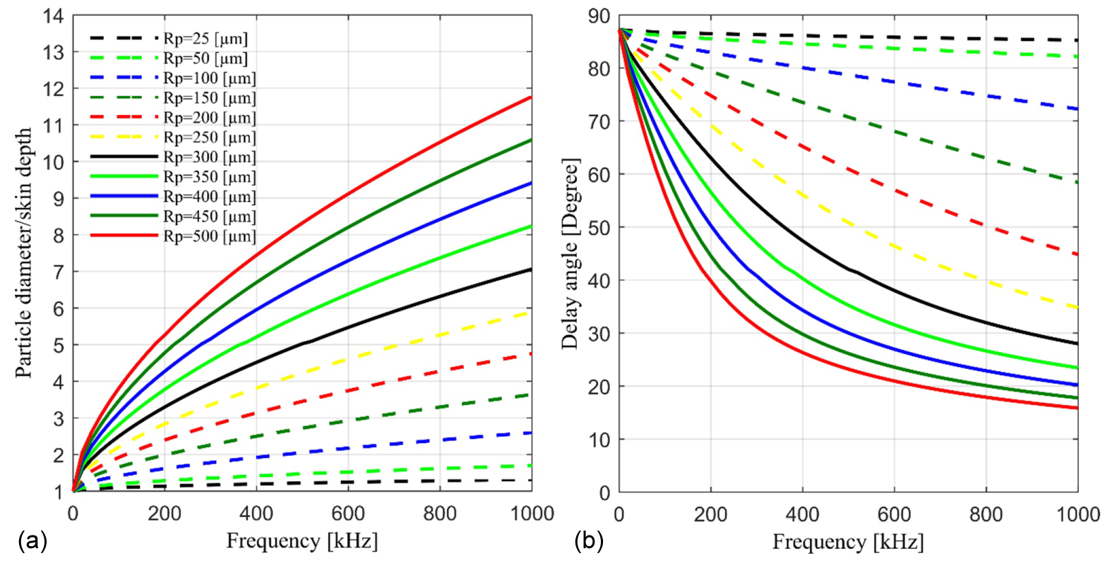
Figure 7: Particle size effect simulation with the...
Particle size effect simulation with the dependence of the magnetic field frequency a) Ratio of particle diameter to skin depth and b) Phase delay angle.
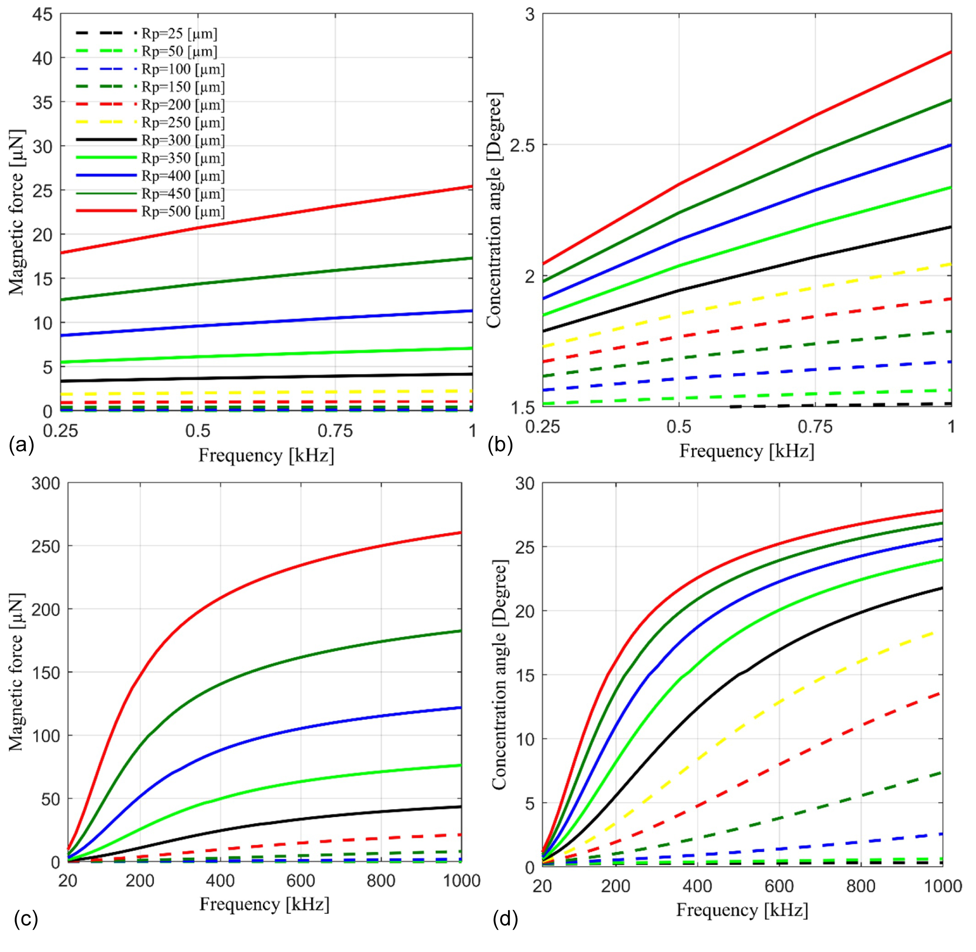
Figure 8: Simulated a) Force and b) Concentration...
Simulated a) Force and b) Concentration angle of the concentration generator with doublet-Halbach-PMQs configuration; c) Force and d) Concentration angle of the concentration generator with doublet-EMQs configuration.
References
- Y Huang, MB Khamesee, E Toyserkani (2016) A comprehensive analytical model for laser powder-fed additive manufacturing. Addit Manuf 12: 90-99.
- J Lin (1999) Simple model of powder catchment in coaxial laser cladding. Opt Laser Technol 31: 233-238.
- John E Brockmann, John R Torczynski, Ronald C Dykhuizen, Richard A Neiser, JE Brockmann, et al. (2002) Aerodynamic beam generator for large particles. US Patent 6,348,687.
- MJ Anderson, RS Budwig, KS Line, JG Frankel (2002) Use of acoustic radiation pressure to concentrate small particles in an air flow. Ultrasonics.
- R Imani, E Robert (2015) Acoustic separation of submicron solid particles in air. Ultrasonics 63: 135-140.
- M Lungu, P Rem (2003) Eddy-current separation of small nonferrous particles by a single-disk separator with permanent magnets. IEEE Trans Magn 39: 2062-2067.
- JR Nagel (2018) Induced Eddy currents in simple conductive geometries: Mathematical formalism describes the excitation of electrical Eddy currents in a time-varying magnetic field. IEEE Antennas Propag Mag 60: 81-88.
- YR Smith, JR Nagel, RK Rajamani (2019) Eddy current separation for recovery of non-ferrous metallic particles: A comprehensive review. Miner Eng 133: 149-159.
- VI Dyadin, VYV Kozhevnikov, AV Kozyrev, NS Sochugov, VG Podkovyrov, et al. (2008) Pulsed electrodynamic separation of small conducting particles. Tech Phys Lett 34: 91-93.
- N Dholu, JR Nagel, D Cohrs, RK Rajamani (2017) Eddy current separation of nonferrous metals using a variable-frequency electromagnet. KONA Powder Part J 34: 241-247.
- F Yu, W Chen, D Zhang (2016) The research of simulation on Eddy current separation process based on MATLAB and COMSOL. Procedia CIRP 56: 520-523.
- JD Jackson (1998) Classical electrodynamics. (3rd edn), John Wiley, New York.
- JD Ray, JR Nagel, D Cohrs, RK Rajamani (2018) Forces on particles in time-varying magnetic fields. KONA Powder Part J 35: 251-257.
- JR Nagel (2018) An analytic model for eddy current separation. Miner Eng 127: 277-285.
- S Elgwel, A Harmer, SW Bowring, NJ Yin (2012) Resolution of multiple concealed threat objects using electromagnetic pulse induction. Prog Electromagn Res 26: 55-68.
- F Morrison (2013) An introduction to fluid mechanics. Cambridge University Press.
- V Saveliev (1998) System and method for separating electrically conductive particles. US Patent 5,772,043.
- H Naidu (2010) Electrodynamic separation of metallic granules from mixed waste stream. The University of Utah.
- SM Wentworth, ME Baginski, DL Faircloth, SM Rao, LS Riggs (2006) Calculating effective skin depth for thin conductive sheets. 2006 IEEE Antennas Propag Soc Int Symp 4845-4848.
- F Marteau, A Ghaith, P N'Gotta, C Benabderrahmane, M Valléau, et al. (2017) Variable high gradient permanent magnet quadrupole (QUAPEVA). Appl Phys Lett 111: 253503.
- S Becker, M Bussmann, S Raith, M Fuchs, R Weingartner, et al. (2009) Characterization and tuning of ultrahigh gradient permanent magnet quadrupoles. Phys Rev Spec Top - Accel Beams 12: 102801.
- K Halbach (1980) Design of permanent multipole magnets with oriented rare earth cobalt material. Nucl Instruments Methods 169: 1-10.
- JK Lim, P Frigola, G Travish, JB Rosenzweig, SG Anderson, et al. (2005) Adjustable, short focal length permanent-magnet quadrupole-based electron beam final focus system. Phys Rev Spec Top - Accel Beams 8: 1-17.
- E Schlömann (1975) Separation of nonmagnetic metals from solid waste by permanent magnets. I. Theory. J Appl Phys 46: 5012-5021.
- SV Kulkarni, SA Khaparde (2004) Transformer engineering: Design and practice. CRC press.
- DW Green, RH Perry (2008) Perry's chemical engineers' handbook. (8th edn), McGraw Hill, New York.
Author Details
Yuze Huang, Mir Behrad Khamesee* and Ehsan Toyserkani
Department of Mechanical and Mechatronics Engineering, University of Waterloo, Waterloo, Ontario N2L 3G1, Canada
Corresponding author
Mir Behrad Khamesee, Department of Mechanical and Mechatronics Engineering, University of Waterloo, Waterloo, Ontario N2L 3G1, Canada.
Accepted: March 07, 2019 | Published Online: March 09, 2019
Citation: Huang Y, Khamesee MB, Toyserkani E (2019) Electrodynamic Concentration of Non-ferrous Metallic Particles in the Moving Gas-powder Stream: Mathematical Modeling and Analysis. Int J Magnetics Electromagnetism 5:019.
Copyright: © 2019 Huang Y, et al. This is an open-access article distributed under the terms of the Creative Commons Attribution License, which permits unrestricted use, distribution, and reproduction in any medium, provided the original author and source are credited.
Abstract
This paper presents theory, modeling, and analysis of a novel electrodynamic concentration approach for submillimeter-sized conductive metal particles focusing in moving gas-powder stream. Such method is of particular interest in blown-powder feeding fabrication industry (e.g., powder-fed additive manufacturing) to generate a tightly focused powder stream. Conceptual design of a concentration generator is proposed with two different configurations: The doublet Halbach permanent magnet quadrupoles (doublet-Halbach-PMQs) and the doublet electromagnet quadrupoles (doublet-EMQs). Analytical models for magnetic forces and concentration angles were built. Numerical calculations were conducted for pure aluminum particles with a radius of . It was found that the magnetic force and the concentration angle increase with an increase of the particle size. The numerical results indicate that the proposed concentration generator with doublet-Halbach-PMQs configuration cannot be effectively used for small-size particle concentration. By contrast, the concentration generator with doublet-EMQs configuration under high frequency is capable to concentrate particles with a radius of . The particles with a radius of can be concentrated with more than angle at the frequency of . Therefore, the proposed doublet-EMQs configuration has a great potential to generate a narrowed and finely focused powder stream in the blown-powder feeding fabrication process.
Keywords
Electrodynamic concentration, Powder-stream focusing, Magnetic force, Eddy current, Halbach quadrupole array, Blown-powder feeding
Introduction
A major challenge in the blown-powder feeding fabrication techniques (e.g., powder-fed additive manufacturing [1]) is to deliver the powder to precise spatial point to satisfy geometric precision. However, current powder feeding methods generally lead to a wide and divergent powder stream, resulting in low powder catchment as well as undesirable geometric accuracy. As shown in Figure 1a and Figure 1b of a lateral blown-powder feeding process, where the powder stream spreads much wider than the laser beam, and the particles that do not impinge onto the laser beam area might not be effectively deposited by a solid-solid surface impact ricochet [2]. Therefore, it is highly desirable to narrow down the diverging powder stream for improving fabrication precision and powder catchment as shown in Figure 1c.
Currently, highly active techniques for small-size particle concentration or separation in gas medium might be categorized as aerodynamics concentration [3], acoustic concentration [4] or separation [5] and eddy current separation (ECS) [6]. One of these promising techniques, the ECS, has been successfully used for non-ferrous metallic particle deflection with a high response efficiency. Basically, ECS utilizes the induced circulating currents in conducting particles to react back on external applied magnetic field by a magnetic force [7,8]. The generated magnetic force has a specific direction that deflects the particles towards to the magnetic field strength decreasing direction. In addition, the generated magnetic force has been shown to be capable of deflecting the particles with size ranging from submillimeter [9] to millimeter [10]. Therefore, with a proper magnetic system setup (e.g., high radial magnetic field gradient), the induced magnetic force may be utilized for non-ferrous metallic particle concentration.
A large number of ECS models have been built to explore this complex process. In the recent review work, Smith, et al. [8] summarized the theoretical models for the magnetic force calculation. Based on their work, the force models can be roughly categorized as numerical and analytical. For the numerical models, the Faraday's law was first utilized to solve the induced electrical field by the external magnetic field B (all vectors are set as bold font in this paper). Ohm's law was then used to calculate the generated eddy current J . Thereafter, the magnetic force F over the particle volume can be calculated as by Finite Element Method with applying fine domain discretization or mesh. For instance, Fengjie, et al. [11] built a new numerical model of the magnetic force by a joint simulation of COMSOL and MATLAB, leading to an efficient calculation for the particle deflection distance. By contrast, a closed-form analytical solution of the magnetic force can be achieved under the linear magnetic field case. The force can be approximated by the magnetic dipole moment model ( [12]), where the magnetic moment M is analytically solved. Ray, et al. [13] and Nagel [14] reported that the analytical models possess a high accuracy in force calculation for systems equipped with the time-variant electromagnetic field source or the permanent magnet source.
Inspired by the ECS technique and the associated magnetic force models, this paper investigates an innovative magnetic concentration approach to focus non-ferrous metallic particles in gas medium. More specifically, the proposed magnetic concentration approach is designed to concentrate the diverging powder stream by directionally deflecting particles in the blown-powder feeding fabrication process. Conceptual designs of the concentration generator were proposed with both permanent magnet (PM) and electromagnet (EM) sources. Numerical simulations were performed to investigate effective magnetic forces and concentration angles as the particles travelling though the proposed concentration generator while considering the particle size effect.
Theory
A few ideal conditions should be assumed in this research. First, as the particles travel through the concentration generator, the powder stream will thin out (e.g. larger diameter 2 ~ 3mm) and the particles will not be substantially impeded by the presence of other particles. Second, the particles' rotation angles tend to be zero during the induced magnetic force action time, which can be explained by the fact that the response time of the eddy current ( , calculated based on reference [15]) is quite small compared with that of the particle rotation period. Third, the effect of the gas drag force on the particle's movement can be ignored. The drag force on the moving particles were calculated based on the fluid mechanics [16] as elaborated in Appendix A. It was found that the magnitude of the drag force is insignificant as it is roughly to that of the effective magnetic force.
Principle of the magnetic concentration approach
Schematic diagram of the proposed concentration approach is shown in Figure 2, where the concentration generator was designed with an annulus shape. This special arrangement provides a magnetic field with high radial gradient that the field intensity decreases significantly from the outer circumferential layer to the inner center region in the transverse cross-section.
According to the Faraday's law of induction, eddy current can be induced in the conducting particles as the particles travel through the alternating magnetic field. Subsequently, the induced eddy current will react back to the applied field by generating a magnetic force that drags the particles towards to the field intensity decreasing direction. Therefore, the outer-layer particles may be driven by the radial magnetic force towards to the inner region of the powder stream.
Magnetic force
As the conducting particles travel through the varying magnetic field of the concentration generator as shown in Figure 3, the induced magnetic force can be expressed as [12],
Where z, r and are the coordinates in the axial-radial-tangential coordinate system. Here should be noted that the displacement current is assumed as zero in the present research, accordingly, in the above Equation 1.
The effective magnetic moment may be derived as [17],
Where α is the magnetic polarization coefficient, μ the magnetic permeability and is the particle volume with radius .
The coefficient α is a complex variable and can be calculated as [18],
Where is a coefficient and is the effective skin depth. The induced eddy current has a non-uniform distribution in depth direction (known as skin effect), the skin depth describes the distance from the surface that the current density reduces to of the surface value. The conventional skin depth can be calculated as,
Where σ is the electrical conductivity and f is the magnetic field frequency. With refer to the small-scale thickness (thickness ) of the particles, the effective skin depth may be expressed as [19],
Therefore, the transient magnetic force on the particle might be calculated as,
Based on the above Equations (3-6), the magnetic force component changes direction as the particle passing through the magnetic field as shown in Figure 3. Consequently, the time-averaged vertical force will be equal to zero. In addition, when the magnetic field frequency is relatively low that the skin depth δ is comparable with the particle size, the magnetic polarization coefficient α will be nearly imaginary. Subsequently, the phase of the induced magnetic moment M will approximately lag the magnetic field B by and the time-averaged magnetic force applied on the particle will be equal to zero. Therefore, the time-averaged radial magnetic force applied on the particle might be approximated as,
Where is the couple coefficient. The couple coefficient k is derived based on the phase delay angle of the magnetic moment and the external magnetic field.
Concentration angle
According to the force derivation elaborated in the above Section 2.1, it is reasonable to assume that the particles will be only affected by the gravity force (mg, g is the gravitational acceleration) and the concentration force () as the particles travel through the concentration generator. The mass of each particle is calculated as , and is the particle density. Thereafter, the particle acceleration time t of the concentration system under length L can be expressed as,
Where and are the initial velocity and divergence angle (shown in Figure 3) when particles enter the concentration generator, respectively. Correspondingly, the final divergence angle and velocity when the particles exit the concentration generator are represented by and , respectively. According to the momentum theorem, simultaneous equations can be derived as,
Subsequently, the concentration angle as the particles travel through the magnetic field can be solved as,
Conceptual Design of the Concentration Generator
To achieve the magnetization configuration of the designed annulus-shaped concentration generator as discussed in Section 2.1, two possible quadrupole-based configuration systems are sketched out in Figure 4a and Figure 4b, where the permanent magnet (PM) and electromagnet (EM) are used as the magnetic sources for these two systems, respectively. The permanent-magnet-based quadrupoles (PMQs) can access to high gradient field, which can reach up to in a typical 10mm bore diameter structure [20]. However, the induced field frequency is limited by the relative motion between the PM source and the particle. By contrast, the conventional electromagnet-based quadrupoles (EMQs) could only achieve due to comparably larger aperture requirement [21]. Nevertheless, the EM source can be easily extended to a high magnetic field frequency.
The norm and radial magnetic field intensity for these two quadrupole-based configurations were shown in Figure 4c and Figure 4d, respectively. As seen, the field intensity is not constant in the same radial layer. To compensate the inconsistent distribution of , a doublet-quadrupoles arrangement is proposed as shown in Figure 4e, where the later quadrupole will have a magnetization with angle difference compared with that of the former one.
Indeed, extremely high gradient fields can be achieved for the PMQs with Halbach array configuration [22], which may produce over under a bore diameter arrangement [23]. To fully explore the Halbach array configuration, a Halbach PMQs array (consisting 16 sections of PM with magnetization oriented at , , in transverse plane, as shown in Figure 5) were investigated here. As presented in Figure 5b, the magnetic field intensity of the Halbach PMQs array decreases rapidly in the radial direction, leading to a high gradient, accordingly, large radial magnetic force can be produced by this configuration. Similarly, the non-uniform field intensity along each radius layer for the inner region ( ) may be compensated by the doublet-quadrupoles arrangement (shown in Figure 4e). Meanwhile, the doublet-Halbach PMQs array can be extended to an alternately N-S and S-N magnetization configuration in the z-axis direction by changing the magnetization distribution of each Halbach PMQs array. Thereafter, a higher field frequency may be generated for the doublet-Halbach PMQs design.
Results and Discussion
Neodymium N52 magnets with residual magnetic intensity 1.45T are incorporated into the designed doublet-Halbach-PMQs. As the nozzle diameter of the powder feeding process is typically smaller than 2mm [1], the Halbach PMQs is built with a compact geometry where the inner radius, outer radius and thickness are set as , and , respectively. Accordingly, the magnet period λ of the designed doublet-Halbach-PMQs may be evaluated by . The equivalent field frequency f can be calculated as .
The magnetic field distribution of the proposed Halbach-PMQs was simulated by COMSOL Multiphysics® software and the averaged field density ( ) and gradient ( ) over the radius zone ( ) were used to evaluate effective concentration forces and concentration angles. Strong field intensity ( ) and high field gradient ( ) [21] were assumed in the EM-quadrupole simulation. The process parameters of both doublet-Halbach-PMQs and doublet-EM-quadrupole configurations are listed in Table 1. Spherical aluminum particles were used in the numerical calculation and the corresponding material properties are listed in Table 2.
Figure 6 shows the simulated magnetic field for the concentration generator with Halbach-PMQs configuration. The field distribution is clearly shown in Figure 6a and the induced radial field intensity within the inner region ( ) of the Halbach PMQs is shown in Figure 6b. As seen, the radial magnetic field intensity increases from the center layer to the circumferential layer within the Halbach PMQs inner region. Figure 6c depicts the magnitude of the rises rapidly towards to the outer circumferential layer along the radius direction, and the magnitude of the corresponding gradient is presented in Figure 6d. Based on the force derivation elaborated in Section 2.2, it can be concluded that the concentration force will be much larger for the particles located in the outer layer of the powder stream than that located in the inner layer, which is desirable since the outer layer particles have a larger divergence than that of the inner region particles.
Figure 7a shows that the ratio of particle diameter to the skin depth increases with an increase of the magnetic field frequency. In addition, the increasing rate of the diameter/skin depth ratio declines with the shrinking of the particle size. For the small-size particles (), the ratio is nearly to one even at the high field frequency (e.g., ). Based on the physical model developed in Section 2.2, lower ratios of diameter/skin depth will lead to higher phase delay angles, which is clearly shown in Figure 7b. This phenomenon can also be explained by the theory that the induced eddy currents are restricted by the lack of space or high resistivity [25]. As seen, the delay angles approach to at the low field frequency case and decreases with the increasing of the field frequency.
Figure 8 demonstrates the calculated magnetic forces and the concentration angles over a wide range of particle sizes for the proposed concentration generators. The simulation results shown in Figure 8a, Figure 8b, Figure 8c and Figure 8d indicate that the effective magnetic force and the concentration angle increase with the enlarging of the field frequency as well as the increasing of the particle size. From Figure 8a and Figure 8b it can be seen that the doublet-Halbach-PMQs configuration cannot be effectively used for small-size particle () concentration and the maximum concentration angle is smaller than for large-size particles . The reason may be attributed to the relatively low field frequency that the induced skin depth is comparable with respect to the particle size. Based on the process parameters listed in Table 1, the equivalent magnetic field frequency of the doublet-Halbach-PMQs configuration is calculated as small as . By contrast, the EM-quadrupole configuration can be easily set with a high-level frequency, which is capable of delivering high magnetic forces and large concentration angles as shown in Figure 8c and Figure 8d. However, for particles with radius , the magnetic force will be insufficient even with high field frequency (e.g., ) as illustrated in Figure 8c. The reason may be explained by the fact that the small-size particles will lead to a low ratio of diameter/skin depth and a large phase delay angle as shown in Figure 7.
Conclusion
A new magnetic approach for non-ferrous metallic particle concentration was proposed and tested while considering the particle size effect. Two different conceptual designs of the proposed concentration generator were analyzed. Effective magnetic forces and the associated concentration angles of the proposed configurations in particle focusing was predicted based on the built analytical model. According to the calculated results obtained in present research, the following conclusions can be drawn:
(1) The proposed concentration generator with doublet-EMQs configuration under high frequency is capable to concentrate aluminum particles with a radius of can be concentrated with more than at the field frequency of . Therefore, the doublet-EMQs configuration possesses a great potential to generate tightly focused powder streams in the blown-powder feeding fabrication technologies.
(2) The proposed concentration generator with doublet-Halbach-PMQs configuration might not effectively be used for small-size particle () concentration. The maximum concentration angle is smaller than even for the large-size particles ().
(3) Particle size has a strong effect on the effective magnetic concentration force as well as the concentration angle. To achieve an effective concentration, the magnetic field frequency should be large enough that the induced skin depth is much smaller than the particle size.
Acknowledgements
The authors would like to acknowledge the financial support of the Natural Sciences and Engineering Research Council of Canada and the China Scholarship Council.