
International Journal of Astronautics and Aeronautical Engineering
(ISSN: 2631-5009)
Volume 4, Issue 1
Research Article
DOI: 10.35840/2631-5009/7524

Article Formats
Radial Turbine Performance Prediction and Design Optimization Whit Matlab Tool
Table of Content
Figures

Tables
Table 1: Turbine VINCI engine.
Table 2: Input data.
Table 3: Rotor geometry.
Table 4: VINCI: Loss models.
Table 5: Results comparison: Radial turbine - VINCI engine impulse turbine.
References
- Rohlik HE (1968) Analytical determination of radial inflow turbine design geometry for maximum efficiency. NASA TN D-4384.
- https://www.snecm.com/.
- Alexander Ponomarenko (2015) RPA: Tool for Rocket Propulsion Analysis.
- Leto A, Bonfiglioli A, Votta R (2016) Preliminary design method of a turbopump feed system for liquid rocket engine expander cycle. Energy Procedia 101: 614-621.
- Leto A, Bonfiglioli A (2017) Preliminary design of a radial turbine for methane expander rocket engine. Energy Procedia 126: 738-745.
- Aungier RH (2005) Turbine aerodynamics: Axial-flow and radial-inflow turbine design and analysis. The American Society of Mechanical Engineers Press, New York.
- Baines NC (1996) Low development in radial turbine rotors. The American Society of Mechanical Engineers, New York.
- Glassman AJ (1976) Computer program for design analysis of radial-inflow turbines. NASA TN D-8164.
- Wasserbauer CA, Glassman AJ (1975) Fortran program for predicting off-design performance of radial-inflow turbines. NASA TN D-8063.
- Moustapha H, Zelesky MF, Baines NC, Japikse D (2003) Axial and radial turbines. Concepts NREC.
- Spraker WA (1987) Contour clearance losses in radial inflow turbines for turbocharges. ASME.
- Ghosh SK, Sahoo RK, Sarangi SK (2011) Mathematical analysis for off-design performance of cryogenic turboexpander trans. ASME Journal of Fluids Eng 133: 031001.
- Leto A (2018) Development and implementation of an engineering tool for the preliminary design of the radial turbine of the turbopump feed system of an expander-cycle rocket-engines fuelled by liquid methane. PhD Thesis, University of Basilicata, Italy.
Author Details
A Leto*
CIRA, Italian Aerospace Research Center, Italy
Corresponding author
A Leto, CIRA, Italian Aerospace Research Center, via Maiorise, 81043 Capua (CE), Italy.
Accepted: February 09, 2019 | Published Online: February 11, 2019
Citation: Leto A (2019) Radial Turbine Performance Prediction and Design Optimization Whit Matlab Tool. Int J Astronaut Aeronautical Eng 4:024.
Copyright: © 2019 Leto A. This is an open-access article distributed under the terms of the Creative Commons Attribution License, which permits unrestricted use, distribution, and reproduction in any medium, provided the original author and source are credited.
Abstract
This work deals with the design of radial turbines, in place of the more commonly used axial ones, to drive the turbo-pumps that supply both the fuel and the oxidizer to the thrust chamber of an expander-cycle rocket-engine.
The present work aims to show a methodology for estimating the compact radial turbine performance prediction for expander cycle rocket engine application, avoiding a detailed fluid dynamics analysis. The Radial Turbine Global Design RTGD code according to the type of fuel, hydrogen, methane or kerosene, determines the optimal velocity triangles, on the mean line, to minimize the overall dimensions, the losses, the flow rate and the pressure ratio, in order to maximize turbine performance for liquid rocket engine application.
The model developed have the objective to estimate the efficiency and optimization of the parameters related to it, and losses prediction.
Keywords
Radial turbine, Rocket engine, Feed system
Nomenclature
A: Area; c: Absolute Velocity; c0: Spouting Velocity; M: Mach Number; P: Pressure; r: Radius; T: Temperature; u: Impeller Tangential Velocity; w: Relative Velocity; z: Number Blades; Δh0: Total Enthalpy Drop; Δhloss: Total Enthalpy Loss; Δp0: Relative Pressure Loss; α: Flow Angle; β1_opt: Inlet Optimum Blade Angle; ω: Angular Velocity
Subscripts
1. Inlet 2. Outlet
Introduction
Radial turbines find nowadays-widespread use in turbochargers for automotive applications, but their use in aerospace applications has not so frequently been reported. Nonetheless, radial turbines have been extensively investigated, both experimentally and numerically, at NASA Lewis Research Centre, starting in the mid-1960s.
Radial turbines have higher efficiency and a high angle of incidence with respect to axial flow turbines [1], thus providing the following advantages: Low expansion ratios, compactness and high reliability at low cost, good performance even with unsteady flows.
The RTGD code features loss models and also allows to account for trailing edge blockage and to compute flow conditions for low pressure ratios at or beyond stator and/or rotor chocking.
In this framework, the data reported by the literature for the axial turbine of the VINCI [1] engine has been used as a test case. In particular, a compare is made between the radial turbine designed by the RTGD tool and the axial impulse turbine used for the VINCI engine, in order to demonstrate the best performance of the radial turbine.
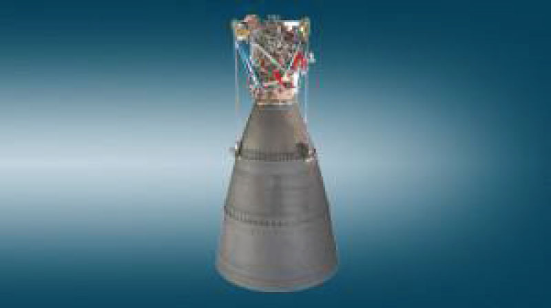
VINCI Engine
VINCI [2] is a new-generation upper-stage, cryogenic rocket engine for launch vehicles, see Figure 1.
VINCI is being developed by Snecma and other European partners as part of a European Space Agency (ESA) program. Firing tests started in April 2005 on a test stand run by the German Aerospace Center (DLR). The Vinci is the upper stage of the Ariane 5. It has a design thrust of 180 [kN], a design Isp of 465 [s] and uses an expander cycle.
In this rocket, hot hydrogen gas, generated in the regenerative cooling passage of the thrust chamber, drives two turbines. The first turbine drives the liquid hydrogen pump, while the second turbine drives the liquid oxygen pump. The two-separate turbo-pumps, each equipped with an inducer, pressurize the propellants.
The schematic of VINCI engine is shown in Figure 2.
The Table 1 lists the primary turbine data of the VINCI engine [2].
Radial Turbine Global Design: General Information
An engineering-based design tool, namely Radial Turbine Global Design RTGD, has been written in Matlab environment to allow a preliminary design of radial turbines for expander cycle engine.
The only limit of Matlab software is that there are no thermodynamic tools already implemented, therefore it was necessary to use the Coolprop libraries [3] to calculate the thermodynamic properties of a wide variety of fluids.
This point is extremely important, because it allows RTGD to always use to real-fluid thermodynamic properties: density, cp, cv, ratio of specific heats γ and viscosity.
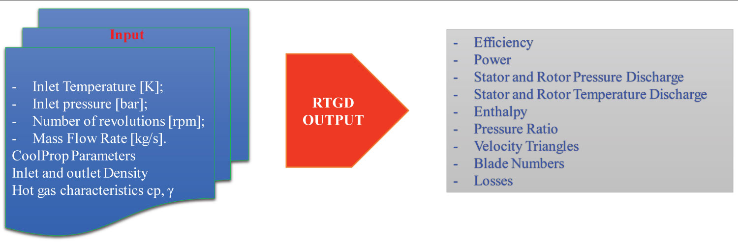
RTGD relies on a one-dimensional model that allows determining several turbine's features, including the turbine's geometry and its efficiency.
The following diagram shows the RTGD inputs and outputs (Figure 3).
The inlet temperature and pressure are defined by the outlet cooling system for expander rocket engine, while number of revolutions and diameter depending by the centrifugal pump [1,4].
The main objective is loss prediction and performance of a radial turbine.
Code Structure
The RTGD [5] code structure can be split in two different parts, in which the second is a consequence of the first and cannot be seen as a standalone code. In addition, the first requires an iterative procedure to compute some of the parameters required in the second part:
Preliminary geometric design
In this first part the turbine geometry and velocity triangles are computed.
Losses prediction
The second part will analyze, using several loss models and correlations, the efficiency that the geometry already produced in the first can achieve.
Running the code using different input parameters allows appreciating their impact on the achievable performance changes. This feature can be clearly considered one of the most important goals of this work, because it can provide an important information for a further design strategy, not only for the expander but also for the cycle parameters.
Loss prediction
In this part, the different types of losses will be analyzed.
The losses in the rotor are associated with many complex phenomena that make the extraction of power from the rotor degraded with respect to what is prescribed by the Euler equation. The losses analysed in this work are estimated in order to determine the radial turbine performance and the effective work done by the rotor blades, and therefore the developed power. We shall consider six different types of losses for VINCI engine: Incidence, passage, tip-clearance, trailing edge, windage losses and kinetic-energy loss at the rotor exit.
The rotor is the main element to be investigated, which is strongly integrated within the turbine, therefore, the radial turbine rotor design represents the most complex element to be realized. The cause of this complexity depends on the three-dimensional fluid-dynamic interactions between the stator and the rotor and between the rotor and casing, which are not entirely known.
The inlet rotor conditions depend on the outlet stator conditions, which in turn depend on the outlet conditions of the cooling system in the expander cycle rocket engine. The outlet rotor conditions depend on the inlet pressure required by the injectors. While, the rotational velocity depends on the mechanical stresses of the centrifugal pump.
The stator outlet flow enters the rotor with an absolute velocity inclined of the α angle with respect to the tangential direction of the reference system.
The rotor rotational velocity generates a dragging speed of the inlet blades which has the same direction as the tangential component of the inlet flow absolute velocity.
The inlet rotor flow relative velocity is a function of the rotor rotation velocity as well as the absolute flow velocity:
In the ideal case the rotor inlet flow has zero incidence, therefore the relative velocity is exclusively radial, so the rotor blades have a radial inlet shape. The null incidence does not allow the minimum value of losses due to the fluid-dynamic nature of the relative flow that enters radially into the blades, since a counter-rotating vortex must be generated which will restore the irrotational conditions of the absolute flow velocity.
Radial blades will be assumed in the implemented model because they have the following advantages, better response to high centrifugal loads, due to the rotational velocity, and mechanical stresses. Furthermore, radial blades are very versatile in off-design conditions because they react well to directions of the relative flow different from the design one.
In the radial blades hypothesis, the incidence will not be null, therefore an unguided component of the flow is generated, therefore the inlet relative flow will have a radial and tangential component.
The model developed RTGD estimates the optimal incidence necessary to minimize losses. The tangential velocity component generated by the non-zero incidence is:
Aungier [6] states that you have minimal losses when the average flow enters the rotor with an incidence generated by one component cu1_slip.
The number of revolutions is a parameter set by the centrifugal pump [7], since the pump is directly connected to the turbine in the expander cycle rocket engine.
Generally, in real applications, a large number of vanes is not used for several reasons, e.g. excessive flow blockage at rotor exit, a disproportionally large wetted surface causing high friction losses, and also because the weight and inertia of the rotor may become too high.
The optimum number of blades [8] in the RTGD is determined by a relationship that is a function of the rotor inlet flow angle α1.
The incidence losses refer to the losses that occur at the inlet of the radial inflow turbine rotor blade passages when the turbine is operating at a non-zero incidence and, therefore, the flow does not enter the passage in the optimum direction. Losses in the rotor blade passage are mainly due to the occurrence of secondary flows, and these are considerably affected by the flow deviation from optimum incidence.
The incidence angle is obtained from the difference between the inlet blade angle and inlet optimum blade angle β1_opt [9]. The experimentally optimum incidence should lie within the range of about -20° to -40° [10]. According Reference [7] the incidence angle value calculated is constant - 31.7 [°] in the case examined in this work.
The term passage losses include a wide spectrum of different phenomena occurring to the fluid crossing the rotor. In fact, after a rapid acceleration in the flow direction, the fluid is turned in the meridional plane along the camber line: this creates a complex pattern of secondary and cross-stream flows, which still today are not completely understood. Moreover, this causes the growth of boundary layers with loss of kinetic energy and blockage. A fully detailed model that considers separately all these loss sources, as the ones existing for the axial turbines, has not yet been developed. In fact, in axial turbine cascades, this can be done by a careful set up and measures, but this is not actually possible for radial turbines, due to the three-dimensionality of the flow pattern, which does not permit to differentiate the losses.
A passage loss model, namely the CETI model [7], was developed to estimate more realistically the losses due to the secondary flow and friction in the rotor passages.
The impeller blades mate up against the turbine housing with a small clearance to avoid mutual contact. In addition, the fluid pushes on the leading surface of each blade essentially creating a pressure difference between the leading and trailing blade surfaces i.e. across the blade. This pressure difference gives rise to a flow through the blade-housing clearance gap. This flow results in pressure dissipation and a consequent loss.
In the radial and axial turbines, the tip clearance is defined as the gap between the rotor blade and the shroud. The radial clearance contributes to generate training the secondary flow and deviation of exit flow angle. The third loss calculated in the RTGD code is the clearance loss, using two equations, the first considering Spraker [11], that considers the leakage flow rate, and the second formulated by Baines [7], model that consider the axial and radial clearances influences. The result provided by the Baines, formula for calculating the loss clearance of the engines is similar than Spraker's.
Trailing edge losses [12] arises due to mixing occurring, as the adjacent rows, of the two-blade surfaces exit the blade row. Moreover, at supersonic velocities shock losses also contribute. In the fourth step the RTGD code determine the trailing edge loss as a function of the exit Mach number, the exit pressure and temperature and relative pressure loss Δp0, as follows:
Windage losses are frictional losses occurring on the back face of the turbine disk. The windage loss [12] is calculated as a function of the Reynolds number.
The only external loss that is usually considered in radial turbine modelling is that of disk friction. This occurs because of the fluid leakage between the rotor disc and the stationary back plate, where the windage flow causes quite strong friction. Depending on the turbine, this leakage could also be recirculated into the turbine annulus or taken away.
The back face of the impeller hub is an annular disk that spins with the impeller. Either this disc may mate with a fixed surface separated from it by a small clearance or it may spin freely far from other fixed surfaces. In either case, the fluid adjacent to the disc exerts a shear on the disc with result that the fluid does unproductive work.
Finally, the rotor exit kinetic loss is expressed as:
Turbine Design
In RTGD tool two different methodologies are implemented for estimating performance, the first [6] function of the inlet and outlet rotor geometry, and by the ratio between the rotor exit velocity and spouting velocity:
This equation shows that the maximum efficiency for a radial turbine is 0.87.
In the second approach the total-to-static efficiency is calculated as a function of the total enthalpy drops and losses:
Therefore, the efficiency is obtaining by the ratio between the total enthalpy drop and total enthalpy losses in the radial inflow turbine stage. In the RTGD are used the turbine geometry thermodynamic parameters of the working fluid, as well as the velocity triangles. This data is necessary for the design procedure, with a loss correlation system, the turbine efficiency can be optimized by varying the parameters of velocity ratio or incidence to minimize the predicted losses.
The turbine exit pressure [13] can be expressed as a function of the work and the total-to-static efficiency:
Test Case Results
This section lists the input data used for the RTGD tool and the output data for radial turbine design.
The input data for RTGD model are given in Table 2.
Table 3 show the radial turbine rotor geometry results.
The radial turbine loss results are show in Table 4.
The RTGD design results and comparison with the experimental data for VINCI engine are provided in Table 5.
In this case the results show that the radial turbine is an advantage compared to the axial one.
Conclusions
The choice of a simple and, therefore, computationally inexpensive simulation tools was motivated by the fact that the RTGD Matlab tool that has been developed are going to be some of the building blocks of a Concurrent Design Facility aimed at design all different components of the entire rocket-engine.
Tools developed in this paper were used to predict the main geometrical parameters and performance characteristics of a radial turbine for a future expander-cycler rocket-engine fed with methane as the liquid fuel.
Several loss models have been incorporated into the code, which showed that the passage and tip clearance losses account for most of the overall losses compared to the other loss mechanisms such as: incidence, trailing edge, windage and exit kinetic energy.
It has been demonstrated that it is indeed possible to use single-stage radial turbines to drive the turbo-pumps that supply methane and oxygen to the thrust chamber of a rocket-engine with characteristics similar to the LM10-MIRA demonstrator that is currently being developed.