
International Journal of Astronautics and Aeronautical Engineering
(ISSN: 2631-5009)
Volume 5, Issue 1
Original Article
DOI: 10.35840/2631-5009/7533

Article Formats
Development of an Aerospike Nozzle for a High Performance Green Hybrid Propulsion (Hpghp) System for Small Satellites
Table of Content
Figures
Figure 1: Over-expanded, optimally-expanded, and under....
Over-expanded, optimally-expanded, and under expanded flow regimes for a conventional fixedgeometry bell nozzle.
Figure 2: Over-expanded, optimally-expanded, and under.....
Over-expanded, optimally-expanded, and under expanded flow regimes for an aerospike nozzle: a) 2-D schematic; b) Thrust chamber components.

Figure 4: Conventional conical nozzle design schematic....
Conventional conical nozzle design schematic.
Figure 5: Design of graphite-sleeve aerospike nozzle....
Design of graphite-sleeve aerospike nozzle.

Figure 6: Aerospike nozzle assembly integrated with.....
Aerospike nozzle assembly integrated with hybrid motor thrust chamber.
Figure 7: 3-D printed one-piece 718-inconel aerospike....
3-D printed one-piece 718-inconel aerospike nozzle and retainer.
Figure 8a: FDM printed fuel grain with ESC-terminated....
FDM printed fuel grain with ESC-terminated electrodes.

Figure 8b: FDM printed fuel grain with ESC-terminated....
FDM printed fuel grain with ESC-terminated electrodes.
Figure 9: Thrust chamber mounted to load- balance ...
Thrust chamber mounted to load- balance test sled.
Figure 10: Piping and instrumentation diagram of...
Piping and instrumentation diagram of the ambient test apparatus, Logan UT.

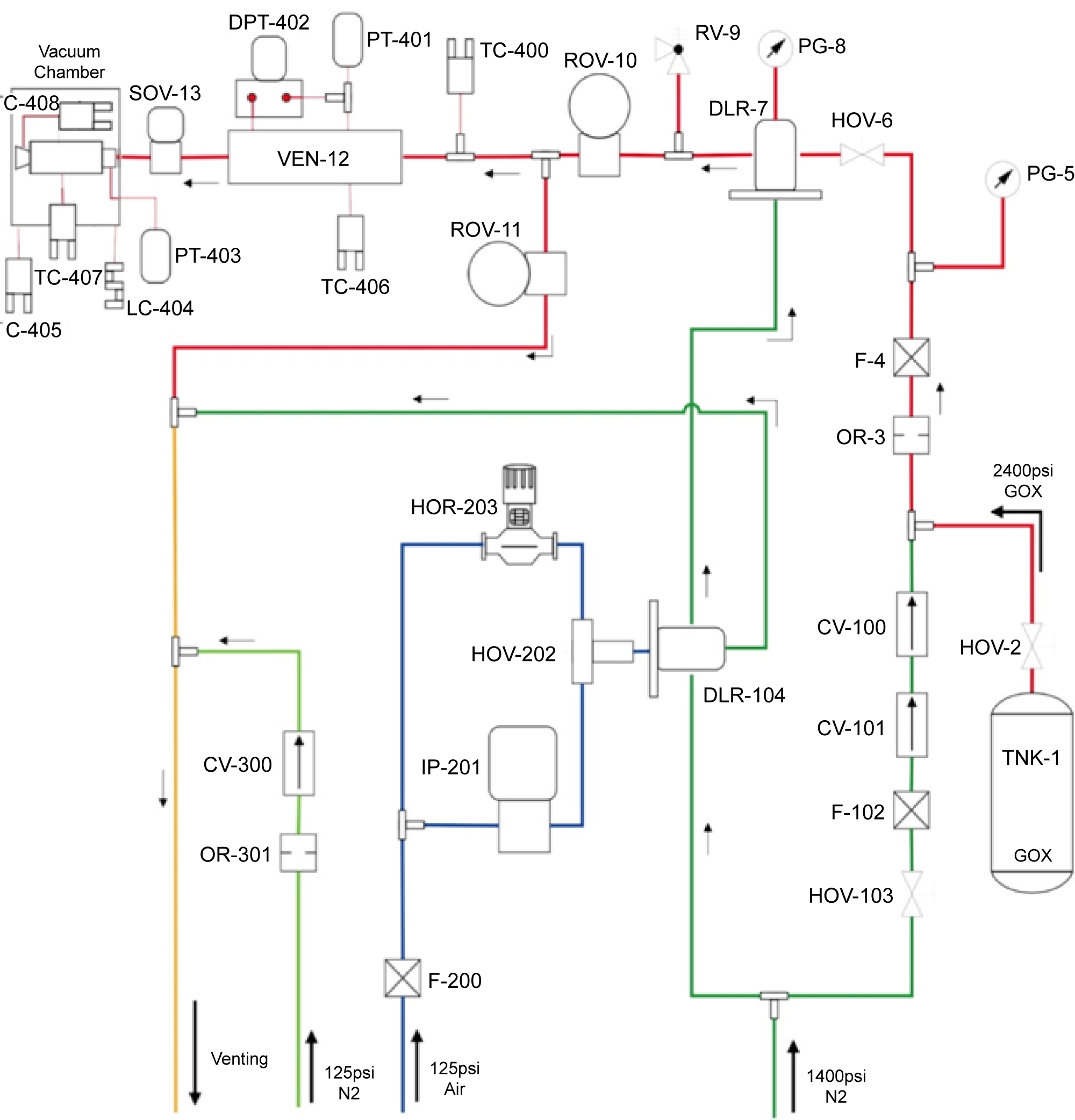
Figure 12: P&ID of MSFC pressure, oxygen delivery...
P&ID of MSFC pressure, oxygen delivery, and vacuum test system.

Figure 13: Thruster mounted in vacuum chamber with....
Thruster mounted in vacuum chamber with labeled features.
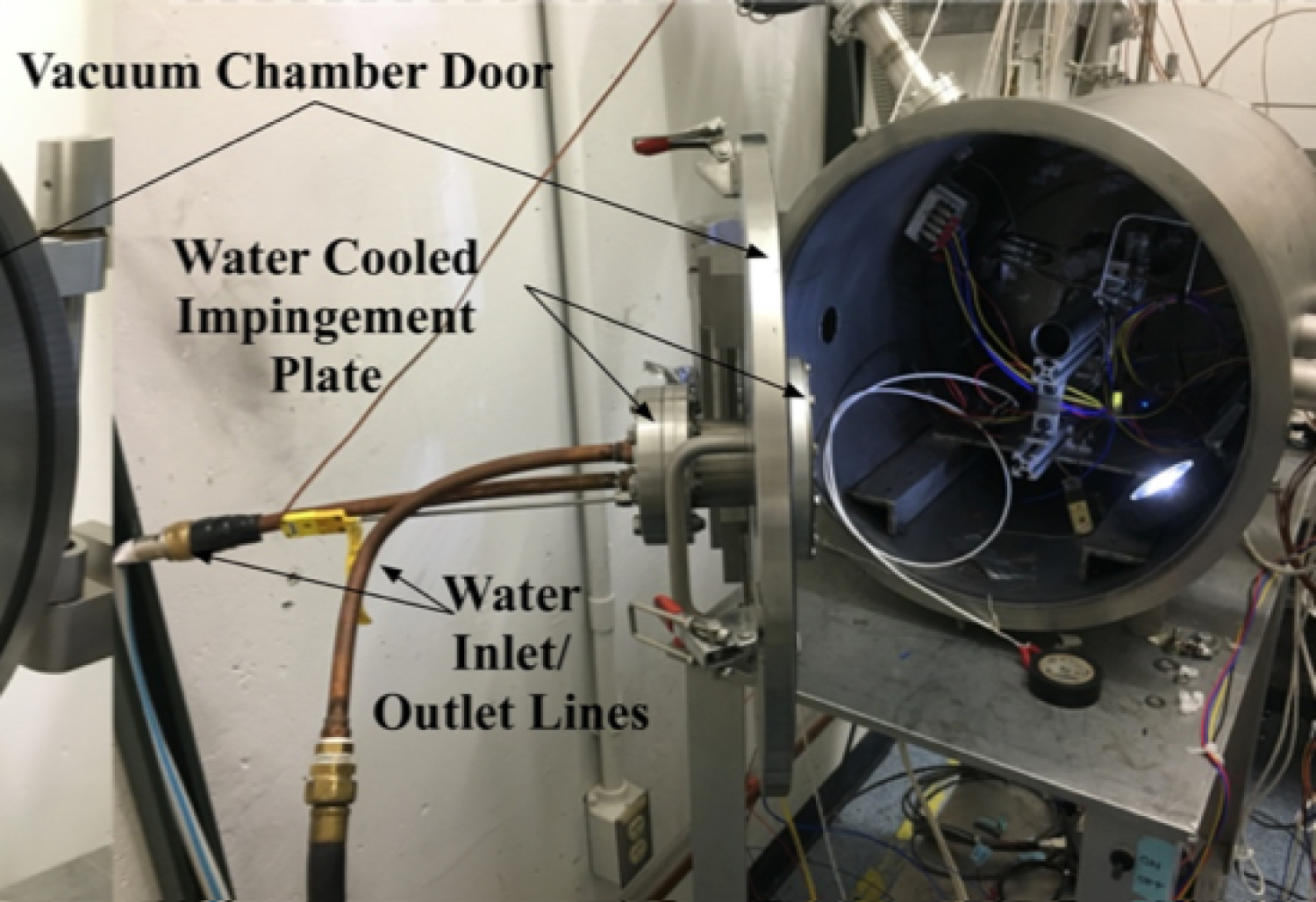

Figure 15: Calculation of the effective burn time from....
Calculation of the effective burn time from chamber pressure time history.
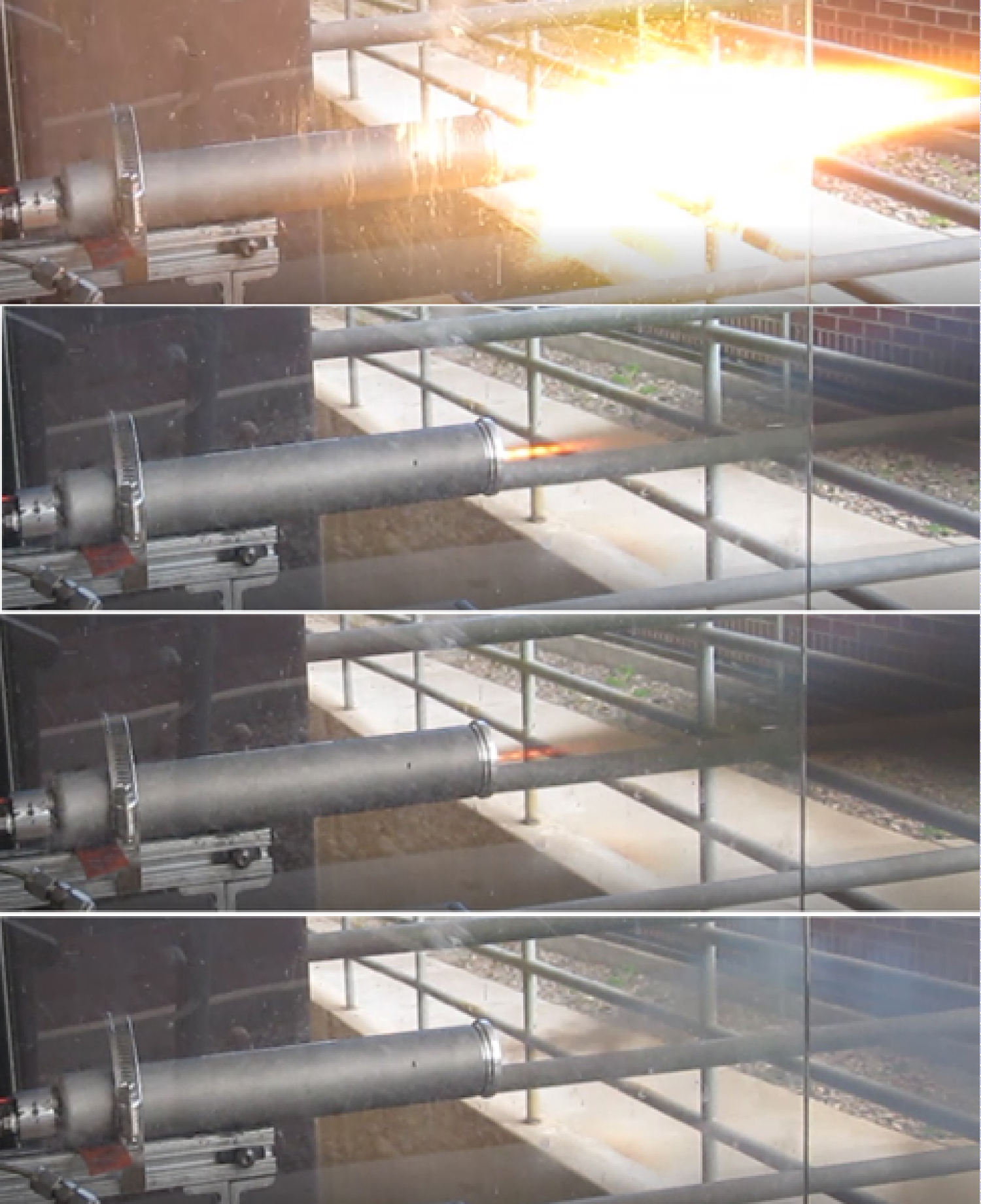
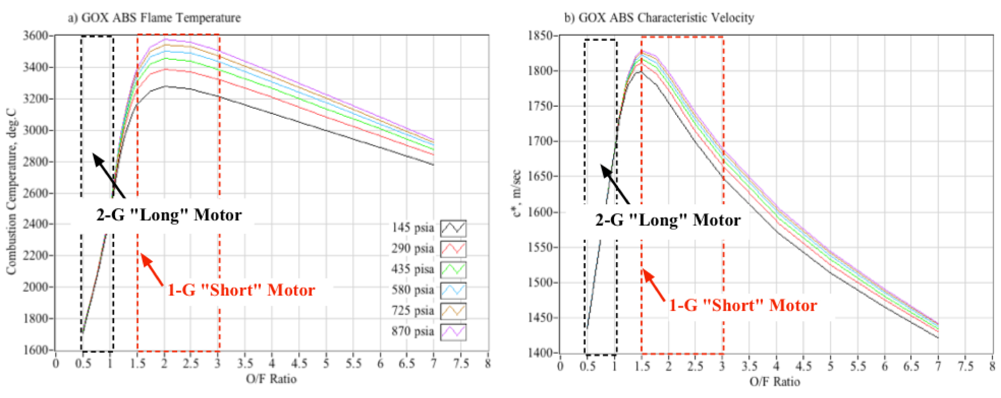
Figure 17: Comparing flame temperatures and performance of long...
Comparing flame temperatures and performance of long (2-G) and short (1-G) fuel grain motors.
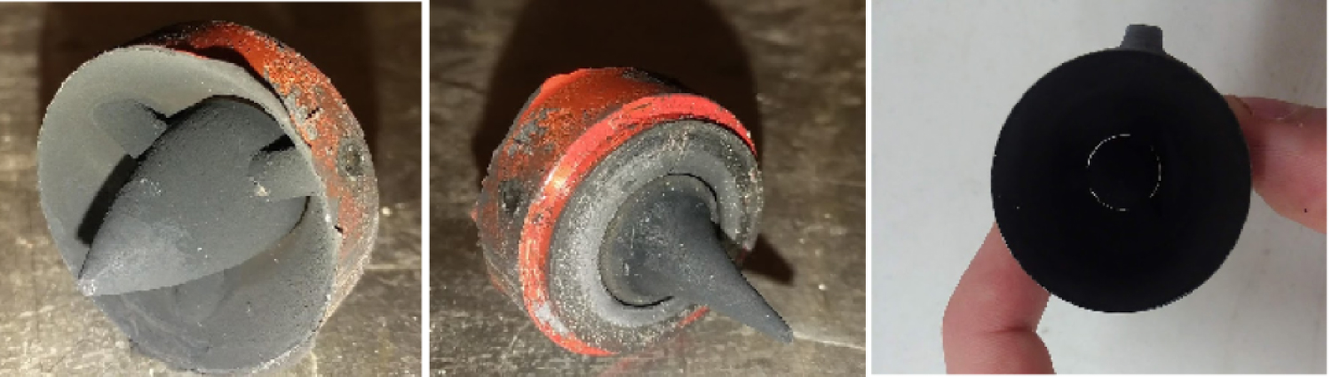
Figure 18: Intact carbon-throat aerospike at completion...
Intact carbon-throat aerospike at completion of ambient testing.
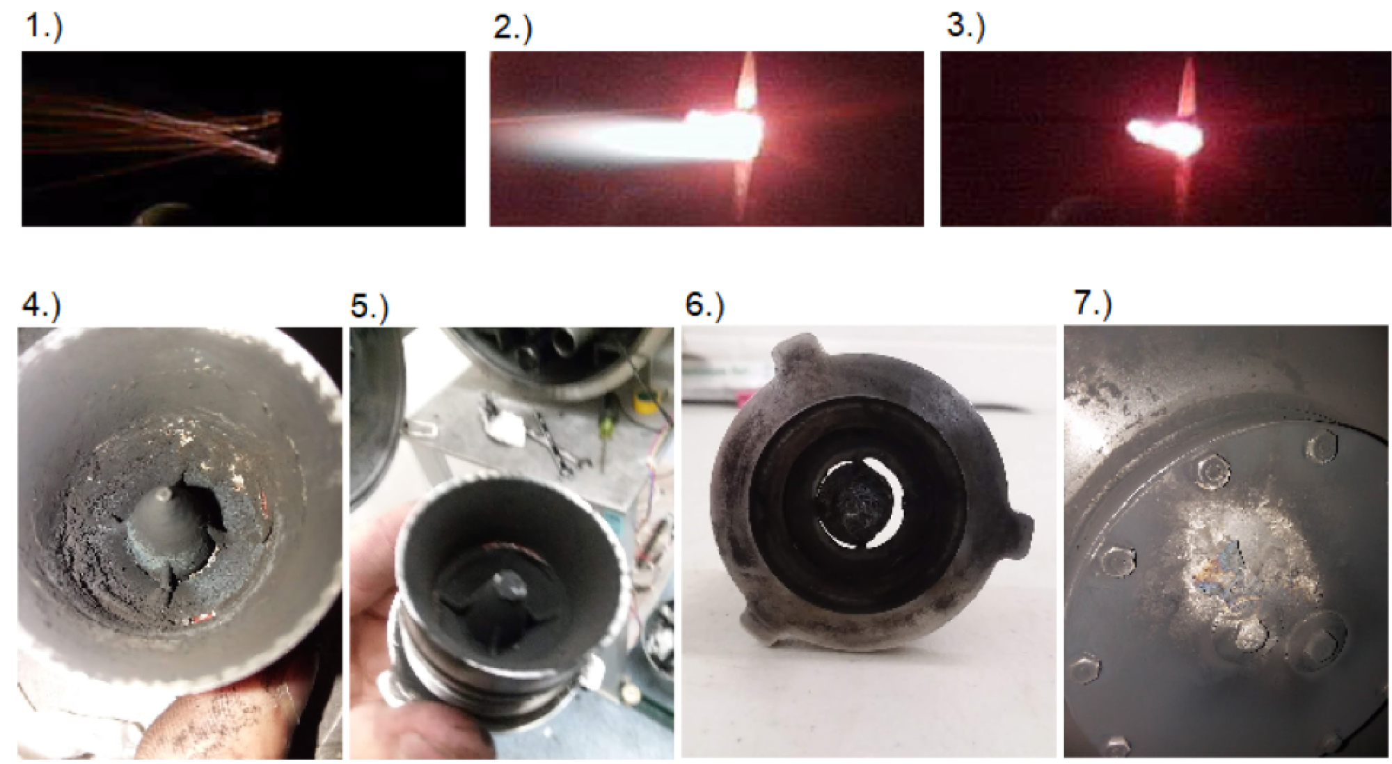
Figure 19: Thermal failure of 3-D printed inconel aerospike nozzle...
Thermal failure of 3-D printed inconel aerospike nozzle: a) Over-expanded conical nozzle exit plume; b) Over-expanded conical nozzle pressure profile, and flow phenomenon interpretation.
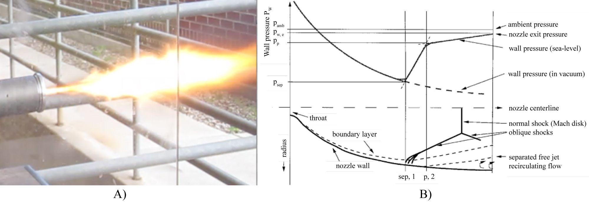
Figure 20: Typical ambient test of the 8.5:12 fixed-geometry...
Typical ambient test of the 8.5:12 fixed-geometry conical nozzle: a) Over-expanded aerospike nozzle exit plume; b) Over-expanded aerospike nozzle flow phenomenon interpretation.10.
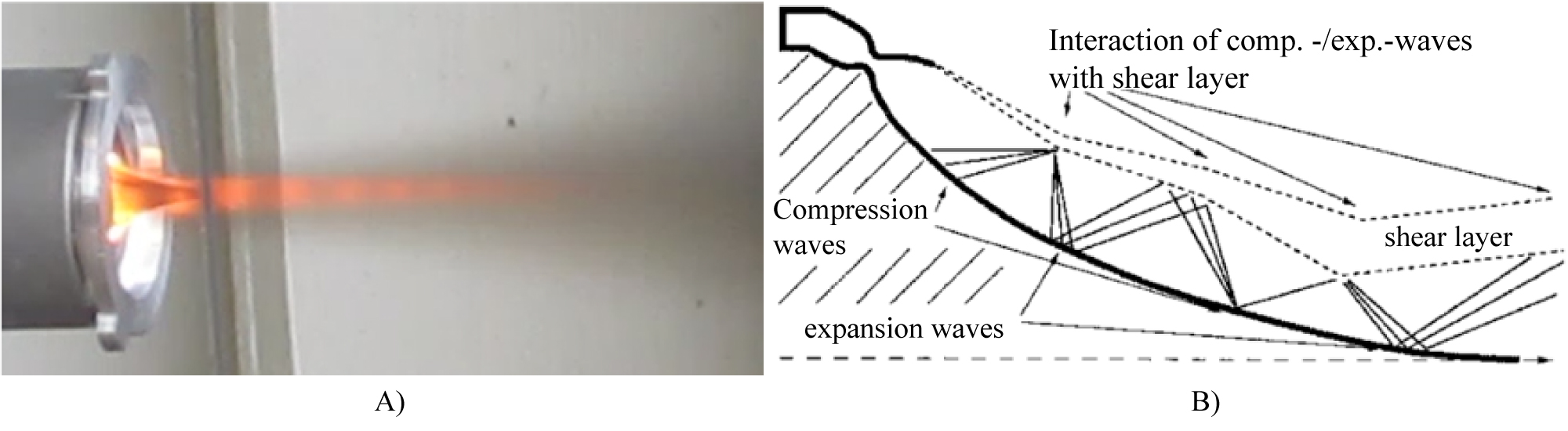
Figure 21: Ambient test of the 8.5:1 aerospike nozzle...
Ambient test of the 8.5:1 aerospike nozzle: a) 2.06:1 conical nozzle; b) 8.5:1 conical nozzle.
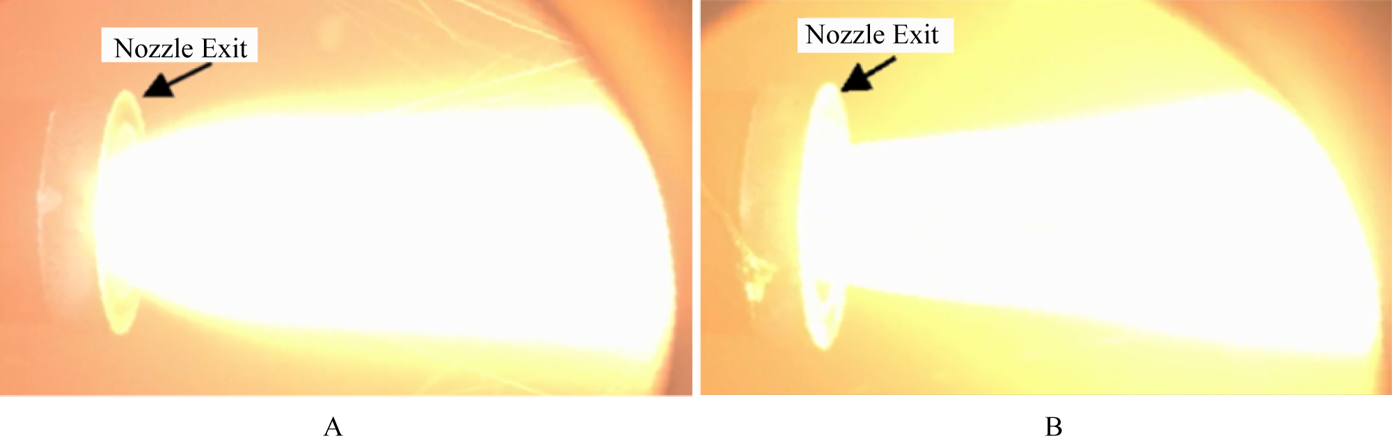
Figure 22: Exhaust plume images from vacuum tests of...
Exhaust plume images from vacuum tests of low (2.06:1) and near-optimal (8.5:1) conical nozzles.
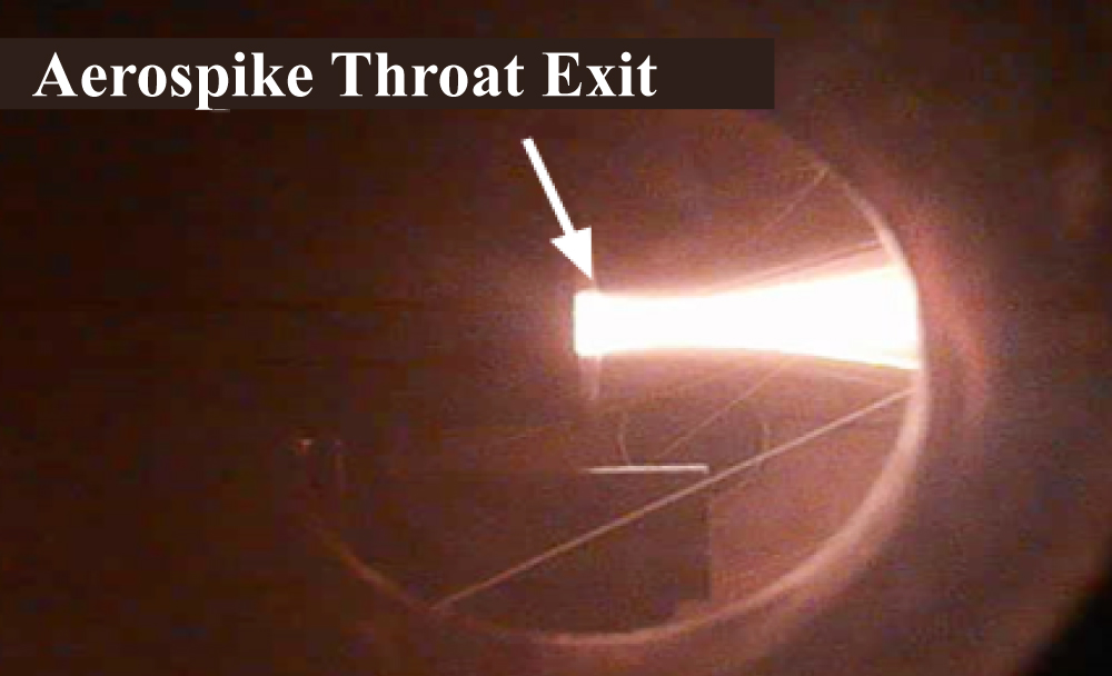
Figure 20: Exhaust plume images from vacuum tests of 8.5:1 expansion....
Exhaust plume images from vacuum tests of 8.5:1 expansion ratio aerospike nozzle.
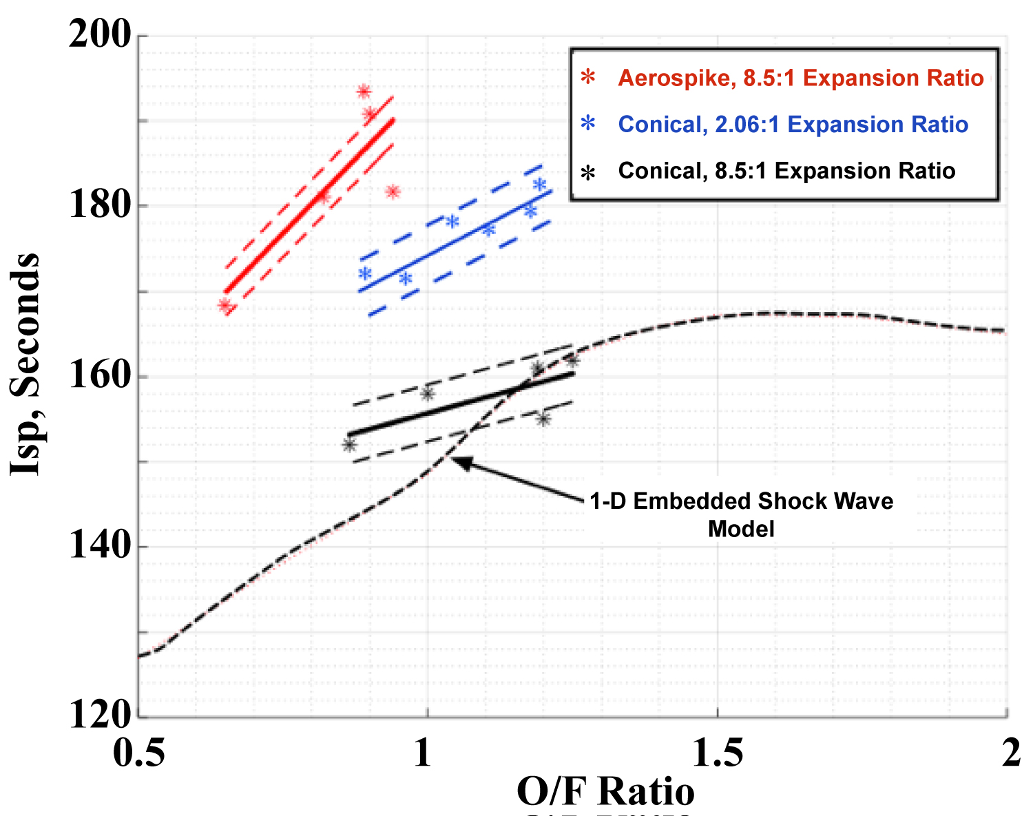
Figure 24: Conventional and aerospike nozzle specific impulse...
Conventional and aerospike nozzle specific impulse comparisons for ambient test conditions.
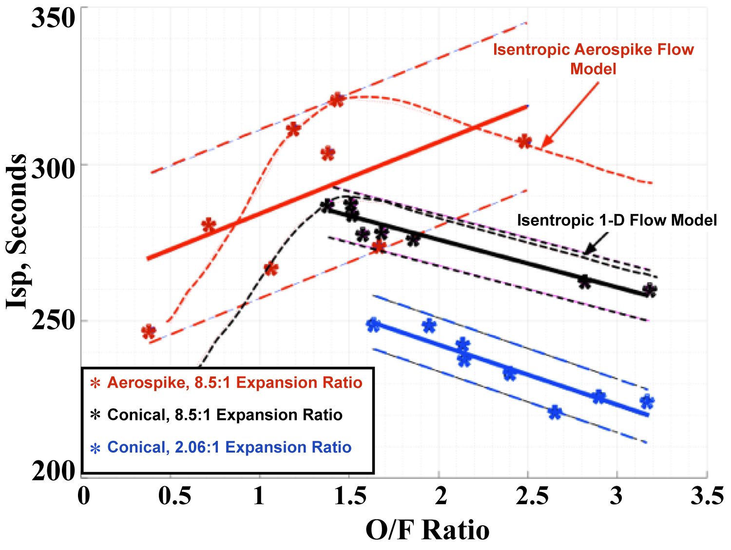
Figure 25: Conventional and aerospike nozzle specific impulse....
Conventional and aerospike nozzle specific impulse comparisons, vacuum test conditions.
References
- Sutton GP, Biblarz O (2001) Rocket Propulsion Elements. (7th edn), Wiley, New York, USA.
- Henzel DK, Huang DH (1992) Design of liquid propellant rocket engines. American Institute of Aeronautics and Astronautics, Washington DC, USA.
- Rao GVR (1961) Recent developments in rocket nozzle configurations. ARS Journal 31: 1488-1494.
- Ladeinde T, Chen H (2010) Performance comparison of a full-length and a truncated aerospike nozzle. 46th AIAA/ASME/SAE/ASEE Joint Propulsion Conference & Exhibit, Nashville, USA.
- Bui T, Murray JR, Bartel CA, Cesaroni A, Dennet M (2005) Flight research of an aerospike nozzle using high power solid rockets. 41st AIAA/ASME/SAE/ASEE Joint Propulsion Conference & Exhibit, Tuscon, USA.
- Anon (2018) 3-D Printed composites materials markets-2018. Report No. SMP-3DPCOMP-1218.
- Lee CC, Thompson DD (1964) Fortran Program for plug nozzle design. NASA TM X-53019, Huntsville, USA.
- Ferrari C (1968) Bodies of revolution with minimal drag coefficient and low heat transfer at high supersonic speeds. J Fluid Dynamics 3: 52-58.
- Maxey K (2014) Metal sintering meets industrial needs with the EOS M 290. Engineering.com.
- Whitmore SA, Merkle.y SL, Tonc L, Mathias SD (2016) Survey of selected additively manufactured propellants for arc ignition of hybrid rockets. Journal of Propulsion and Power 32: 1494-1504.
- Mathias SD, Whitmore SA, Harvey R (2017) High voltage breakdown and arc-tracking mechanism of thermoplastics with applications to hybrid rocket arc-ignition. 53rd AIAA/ASME/SAE/ASEE Joint Propulsion Conference & Exhibit, Atlanta, Georgia, 9-12.
- Whitmore SA (2015) Additively manufactured acrylonitrile-butadiene-styrene-nitrous-oxide hybrid rocket motor with electrostatic igniter. J Propulsion and Power 31: 1217-1220.
- Whitmore SA, Inkley NR, Merkley DP, Michael I, Judson MI (2015) Development of a power-efficient, restart-capable arc ignitor for hybrid rockets. Journal of Propulsion and Power 31: 1739-1749.
- Whitmore SA, Bulcher AM (2017) Vacuum test of a novel green-propellant thruster for small spacecraft. 53rd AIAA/SAE/ASEE Joint Propulsion Conference.
- Whitmore SA (2018) Three-dimensional printing of "green" fuels for low-cost small spacecraft propulsion systems. Journal of Spacecraft and Rockets 55: 13-26.
- Armstrong Isaac W (2019) Department of mechanical and aerospace engineering. Utah State University, USA.
- Anderson JD (2003) Modern compressible flow. (3rd edn), The McGraw Hill Companies, New York, USA, 127-187.
- Gordon S, McBride BJ (1994) Computer program for calculation of complex chemical equilibrium compositions and applications. NASA Technical Report RP1311.
- Whitmore SA, Merkley SL (2016) Effects of radiation heating on additively printed hybrid fuel grain o/f shift. 52nd AIAA/SAE/ASEE Joint Propulsion Conference.
- Hagemann G, Nguyen TV, Dumnov GE (1998) Advanced rocket nozzles. Journal of Propulsion and Power 14: 620-634.
- Sidambe AT, Tian Y, Prangnell PB, Fox P (2019) Effect of processing parameters on the densification, microstructure and crystallographic texture during the laser powder bed fusion of pure tungsten. International Journal of Refractory Metals and Hard Materials 78: 254-263.
Author Details
Stephen A Whitmore1* and Isaac W Armstrong2
1Professor, Mechanical and Aerospace Engineering Department, Utah State University, USA
2Graduate Research Assistant, Mechanical and Aerospace Engineering Department, Utah State University, USA
Corresponding author
Dr. Stephen A Whitmore, Professor, Mechanical & Aerospace Engineering Department, Utah State University, Logan Utah, 84322-4130; AIAA Associate Fellow, USA.
Accepted: April 13, 2020 | Published Online: April 15, 2020
Citation: Whitmore SA, Armstrong IW (2020) Development of an Aerospike Nozzle for a High Performance Green Hybrid Propulsion (Hpghp) System for Small Satellites. Int J Astronaut Aeronautical Eng 5:033.
Copyright: © 2020 Whitmore SA, et al. This is an open-access article distributed under the terms of the Creative Commons Attribution License, which permits unrestricted use, distribution, and reproduction in any medium, provided the original author and source are credited.
Abstract
The Aerospike Nozzle is well-known for altitude compensating capability; however, the aerospike also presents the advantage of a small form factor at high expansion ratios. Aerospike nozzles can be more than 75% smaller than a conventional nozzle with the same expansion ratio. This feature presents a significant potential for volumetric improvements of SmallSat scale space propulsion systems. This research campaign quantitatively assesses the potential advantages of using an aerospike nozzle for a small-scale hybrid propulsion system. Two aerospike nozzles were fabricated during the course of this development campaign, one using conventional manufacturing methods, and one leveraging the capabilities of modern 3-D printing. The conventionally manufactured nozzle was fabricated from graphite, stainless steel, and aluminum, and consisted of a complex assembly with multiple pieces. The second nozzle was manufactured using 3-D laser sintering technology, and was printed as a single piece from Inconel 718 super-alloy. The aerospike contours were integrated into an existing small-scale hybrid motor that had been previously tested using both optimally-expanded and over-expanded conventional fixed-geometry nozzles. Both ambient and vacuum tests were performed, with the conventional and 3-D fabricated aerospike nozzles exhibiting equivalent performance and burn lifetimes. Both aerospike nozzles exhibited superior performance compared to conventional fixed-geometry nozzles.
Nomenclature
Ac: Fuel port cross-sectional area, cm2; Ae: Nozzle exit area, cm2; As: Cross-sectional area at shock wave position, cm2; A1: Venturi inlet area, cm2; A2: Venturi outlet area, cm2; A*: Cross-sectional area at which local flow chokes, cm2; CF: Thrust coefficient; ce: Effective exhaust velocity, m/s; Gox: Oxidizer massflux, g/cm2-s; Gtot: Total massflux, g/cm2-s; Isp: Specific impulse, sec; L: Fuelgrain length, cm; M1: Mach number upstream of shock wave; Me: Exit plane mach number with embedded shock wave; DMfuel: Consumed fuel mass, g; : Fuel mass flow, g/s; : Oxidizer massflow, g/s; : Total mass flow through the nozzle, g/s; O/F: Oxidizer/fuel ratio; O/Factual: Actual oxidizer-to-fuel ratio; O/Fstoich: Stoichiometric oxidizer-to-fuel ratio; P1: Venturi inlet pressure, psia; P2: Venturi throat pressure, psia; P0: Venturi flow path stagnation pressure, psia; P02/P01: Stagnation pressure ratio across shock wave; Rg: Gas constant, J/kg-K; rL: Longitudinal average of the fuel port radius, cm; r0: Initial fuel port radius, cm; T: Venturi flow path temperature, K; T0: Stagnation temperature, K; t: Time, s; tburn: Burn time, s; : Combustion efficiency; : Nozzle expansion ratio, ; : Equivalence ratio; : Ratio of specific heats; : Solid fuel density, g/cm3; : Time derivative, ( )/s.
Introduction
Over the past decade at the USU Propulsion Research Lab a novel High-Performance "Green" Hybrid Propulsion (HPGHP) system has been underdevelopment as an environmentally sustainable replacement for hydrazine and other highly-toxic spacecraft propellants. HPGHP is enabled by recent advances in 3-D printing and leverages unique electrical breakdown characteristics of printed plastics like ABS and polyamide. Additive manufacturing changes the electrical breakdown properties, and when printed materials are presented with an inductive electrical potential, electrical-arcing along the layered surface pyrolizes material and seeds combustion when an oxidizing flow is introduced. Multiple prototype units with thrust levels varying from 4.5 N to 900 N have been developed and testeda,b. Typical startup sequences require less than 2 joules; and once started, the system can be sequentially fired with no additional energy inputs requiredc. On March 25th, 2018 a flight experiment containing a 10-N prototype was launched aboard a sounding rocket from Wallops Flight Facility, and achieved apogee of 172 km, allowing more than 6 minutes in hard-vacuum environment. The thruster was successfully fired 5 times in flight. Whitmore and Bulcher (2018)d report the details of this flight test experiment. This research article presents the results of a development camping where the 10-N test article was modified to fit an aerospike nozzle system in place of the conventional nozzle as previously tested and flown on the suborbital flight tests. Advantages and disadvantages of the aerospike nozzle configuration, compared to a conventional conical nozzle are presented.
Conventional fixed-geometry rocket nozzles allow optimum performance only at one specific ambient pressure or operating altitude. Thus, conventional nozzles necessarily represent a design compromise. In a conventional nozzle combustion gases are choked by a cylindrical throat and then expand through a diverging nozzle pathway, exchanging thermal energy for kinetic energy, and creating a large increase in momentum of the exit plume. The optimal operating condition for a conventional nozzle occurs when the pressure at the exit plane exactly equals the background ambient pressure, and this condition is rocket's set by the chamber pressure and expansion ratio. Figure 1 shows the flow fields associated with an over-expanded, optimally-expanded, and under-expanded bell nozzle [1]. For the conventional nozzle careful design is needed to achieve desired high altitude (under-expanded operating conditions) performance while avoiding flow separation and an embedded shock wave when operating at low altitudes (over-expanded operating conditions).
The over-expanded nozzle develops an exit pressure that is less than the surrounding atmospheric pressure, and a locally negative pressure gradient results. When the negative pressure gradient becomes sufficiently strong, boundary layer separation and backflow can form along the nozzle walls. Backflow and flow separation typically result in the formation of an embedded shockwave. The embedded shock wave leads to a loss of performance, and possible structural failure due to high heating levels at the shock-wall interface and dynamic loads due to flow separation.
For under-expanded conditions the nozzle is fully started and isentropic; however, the exit plane pressure is substantially higher than ambient; meaning that the only a portion of the thermal energy of the plume has been recovered and converted into kinetic energy. The result is the potential for a considerable loss in the available nozzle momentum thrust. Consequently, typically lower expansion ratio nozzles are used for low altitude operation, and high expansion ratio nozzles are reserved for near-space operations. Few designs are able to bridge the gaps between operating altitudes.
Figure 2 shows the flow fields associated with the aerospike nozzle [2,3]. For the aerospike nozzle, the external streamline is unconstrained, and the flow path is essentially opposite of a conventional nozzle. The plume flow is radially directed inward from an annular throat, with the plume being directly exposed to external flow streamline. The aerospike plume is thus directly coupled to the external environment, and is free to expand or contract based on the ambient pressure level. This feature allows for continuous altitude compensation. Consequently, a very high expansion ratio nozzle -- designed for efficient vacuum performance -- can also operate effectively and safely at low altitudes and higher operating pressures.
The aerospike nozzle shape has long been known for its potential altitude compensating capability; however, the aerospike geometry also presents an additional advantageous feature that is not generally recognized and acknowledged. Because most of the delivered thrust of the aerospike nozzle results from the upstream section of the spike, the nozzle can be truncated significantly from the theoretically optimum shape with little decrease in performance. Thus, truncated aerospike nozzles can be less than 25% the length of a conventional bell nozzle with the same performance level [4].
On a small spacecraft, replacing a high-expansion ratio bell nozzle with an aerospike would significantly increase the volumetric efficiency of the configuration. This feature offers the possibility to provide significant savings in performance and overall system weight for in-space operations. Testing conducted by Bui, et al. [5] (NASA, 2005) concluded that switching to a comparable aerospike nozzle can result in mass savings of greater than 8%.
To date, aerospike nozzles have not been seriously considered for small satellite (SmallSat) propulsion systems due to the complexity of the plug systems support structures, and the associated manufacturing difficulties that do not scale well to small sizes. Furthermore, due to the relatively small annular throat gap and associated viscous boundary layer heating, for a given thrust level aerospike nozzles experience significantly higher heating levels that do conventional nozzles. The ability to manage this excess heating is exacerbated at small scales. Using conventional materials, SmallSat-scale aerospike nozzles would require complex external cooling schemes or otherwise experience limited operating lifetimes.
Fortunately, the emergence of 3-D metallic printing for refractory metals like tungsten, niobium, molybdenum, and rhenium offers a potential breakthrough that may allow the advantages of the aerospike nozzle to be realized for SmallSat operations. These refractory materials have been traditionally used in applications where their exceptional heat and wear resistance are required. Incentivized by the recent boom in additive manufacturing, there has been a growing interest in 3-D printing of refractory metals with for aerospace, medicine, nuclear power, and other general industrial applications.
Traditionally, high temperature refractory materials have not been 3-D print capable due to the difficulty of turning these metals into spherical-powders that are compatible with modern laser sintering methods. Recently, several companies in Germany, the United States, Japan and other countries have perfected core technologies that overcome the problem of turning refractory metals into 3-D printing materials. The refractory metal spherical powders for 3-D printing are now available in bulk, and are ready to be applied in the key components of aerospace industry [6].
Test Article Design
In order to assess the feasibility and advantages of 3-D printing aerospike nozzles for SmallSat propulsion applications, a series of experiments were conducted using a legacy flight weight small scale HPGHP thruster system with a nominal thrust level that is variable from 10-25 N, depending on the oxidizer feed pressure and resulting mass flow. The hybrid thruster for this testing campaign used gaseous oxygen (GOX) and 3-D printed acrylonitrile butadiene styrene (ABS) as propellants. Prior to this test series, the legacy motor had been successfully fired more than 100 times, and was well characterized. This test series compared the system performances using both fixed-geometry low (2.06:1) and higher (8.5:1) expansion ratio nozzles, against the same system retrofitted to use the higher (8.5:1) expansion ratio aerospike nozzle.
Thrust chamber
Figure 3 presents a 2-D schematic and photograph of the disassembled HPGHP motor. Depicted are the major components; i) graphite nozzle, ii) nozzle retention cap, iii) motor case, iv) 3-D printed fuel grain with embedded electrodes, v) insulating phenolic liner, vi) chamber pressure fitting, and vii) single-port injector cap. The 38-mm diameter thrust chamber is constructed from 6061-T6 high-temperature aluminum, and was procured commercially from Cesaroni Ince. Generally, two motor case lengths are available; a 1-G configuration that accepted a fuel grain of length up to 6.85 cm, and a 2-G configuration that accepted a longer fuel grain with length of up to 12.69 cm.
Figure 4 depicts the conical nozzle assembly. Pictured, clockwise from the top left are i) The 8.5:1 nozzle contour, ii) A 3-D CAD model of the nozzle insert, iii) The nozzle retainer assembly, and iv) The nozzle assembly integrated onto the hybrid motor case. The fixed geometry nozzles were conventionally manufactured, and featured a graphite sleeve designed to withstand the heating loads with minimal erosion during the test firings.
Figure 5 shows the original design for the aerospike nozzle assembly. The spike contour downstream of the nozzle throat is ideally determined by the desired expansion ratio, and was calculated using the methods of Lee and Thompson [7]. The contour of Ref. [7] assures that the flow along the nozzle spike will remain nearly isentropic and free of strong shock waves, even for highly over-expanded flow conditions. The geometry upstream of the throat can be more arbitrary. As long as a convergence on the nozzle throat produces choked flow, the nozzle will function. In an effort to reduce the stagnation area on the front end of the central spike and minimize heating, an aerodynamic Von Karman-type of ogive profile was chosen for the upstream contour. This profile belongs to a series of functions known as Haack series [8].
Nozzle configurations
Like the conical nozzle, the original design was conventionally fabricated, and featured a graphite sleeve to withstand the heating loads. Clockwise from the top left, Figure 5 depicts; i) Graphite spike assembly and aluminum end piece, ii) CNC fabricated cantilevered spike contour, iii) Full assembly CAD view, iv) Picture of final assembly, v) Stainless steel support arms, and vi) The graphite spike assembly. Figure 6 shows the aerospike nozzle assembly integrated with Cesaroni motor thrust chamber.
Later the design of Figure 5 was reproduced using Direct Metal Laser Sintering (DMLS) capability at the NASA Marshall Space Flight Center. Manufacturing was funded under a cooperative agreement between NASA and USU, with the part being built as a "ride-along" using spare build volume during the printing of another component for NASA Space Launch System. Nozzles printed from refractory metals was not an option within the budget constraints of the current study. Metals currently available at MSFC for 3-D printing purposes include tungsten, which possesses the highest known melting point of any metal, and Inconel 718, a nickel- chromium super-alloy known for its high-strength at high temperatures. Both of these metals are available in powdered form, a necessary for their utilization through additive manufacturing. Inconel prints typically take 1-2 days to complete. Due to the high melting point tungsten prints require significantly more energy, and depending on the size of the print can take more than a week to complete. Thus, due to the experimental nature and higher programmatic risk of this campaign, Inconel was selected over Tungsten as a cost and time saving measure.
The entire assembly including threads, center spike, and mounting threads was printed 718-Inconel using an EOS- M290 DMLS powder bed machine [9]. The printed threads were designed to directly interface the nozzle assembly to the Cesaroni motor case. Figure 7 shows the 3-D Aerospike Nozzle Assembly printed as a single monolithic piece. The printed Inconel-718 piece was bonded to the nozzle retaining cap using high temperature RTV adhesive.
Fuel grains
The printed fuel grains were fabricated using a Stratasys Dimension 1200-ES® fused deposition model (FDM) printerf. Whitmore, et al. (2016) [10] investigated multiple commercially available 3-D printer feedstocks, and determined that ABSplus-340® feed-stockg exhibited to best overall arc-ignition and burn-performance characteristics. Currently, work is on-going to develop "designer" feed-stock plastic alloys that optimize the performance for propulsion applications [11]. Conservatively, in order to ensure adequate performance and operating characteristics for this testing campaign, all fuel grains were printed using Stratasys ABSplus-340® feed-stock.
Ignition system
Motor ignition relies on the patented arc-ignition system developed at Utah State University by Whitmore [12] and Whitmore, et al. [13] The fuel grains used for this test series are based a standardized design developed at the USU Propulsion Research laboratory. Figure 8 shows the pre-combustion chamber design that features two impingement shelves intended to trap and mix the injected oxidizer with the pyrolized fuel. Two electrodes, insulated by industry standard ESC-connectorsh, are embedded into the top face of the fuel grain. Wires are routed from the electrodes to small gaps located on the impingement shelves. The wires are insulated by printed circular sots that insert into the electrode wire gaps. The conducting paths terminate facing each other, flush with the combustion port surface, and exposed to the interior of the combustion chamber.
When an electrostatic potential is placed across the electrodes, electricity flows through a pre-existing surface arc-track, resulting in pyrolysis and ignition as soon as oxidizer flow is initiated. Typically, the arc-track is pre-set by doping the surface with graphite powder.
Once a surface arc-path has been set, graphite doping is no longer required. The fuel grain terminals are connected to mating connectors on the injector cap, and the phenolic liner is placed on the outside of the fuel grain. The entire assembly slides into the motor case.
The ignition system power processing unit (PPU) is based on the UltraVolt® D-series line of high-voltage power supplies (HVPS)i. Figure 9 shows the layout of the arc-ignition system. This HVPS provides the inductive ignition spark that pyrolyzes sufficient ABS material to seed combustion. The D-series HVPS units take a 15-volt DC input and provide a current-limited (7.5 mA) high voltage output -- up to 1000 V or 6 Watts total output. Previous experience with this ignition system has demonstrated that ignition can be reliably achieved using as little as 3 watts. Depending on the impedance on the arc path between the ignitor electrodes, the dissipated voltage typically varies between 10 and 400 volts. Total energy of ignition is typically less than 3 Joules.
Laboratory Test Apparatus
The same instrumentation system was used for both the ambient pressure tests performed at Utah State and the Vacuum tests performed at NASA MSFC. However, due to the different safety demands of both organizations, different oxidizer delivery systems were used for the USU-based and MSFC-based testing campaigns. This section describes the two test systems in detail.
Experimental apparatus for ambient test conditions
All ambient tests were performed in the Propulsion Research Laboratory, located at Utah State University. Depicted is the fully assembled thrust chamber mounted to the test-sled. Figure 9 shows the flight weight motor assembled and ready for testing, and mounted to the test load balance. Figure 10 shows the piping and instrumentation diagram (P&ID) and the USU ambient test systems. Figure 11 shows the detailed layout of the test instrumentation deck. The instrumentation deck was designed to be portable so it could be used for both for the ambient pressure tests at USU and the vacuum tests at MSFC. Test stand instrumentation include venturi-based GOX mass flow, load-cell based thrust, chamber pressure, and multiple temperature readings at various points along the flow path. The differential venturi pressure transducer was installed to increase the accuracy of the sensed pressure drops. The thrust-stand support members allow bending along the direction of thrust to prevent them from interfering with the measured load. The entire test assembly is made using commercially available T-slotj extruded-aluminum components.
Directly aft of the thrust chamber lies the solenoid actuated GOX run-valve. The solenoid flow valve is actuated via a digital out command from the instrumentation. The National Instruments (NI) USB-6002 is shown in Figure 8 as the "Ignition Control" because it sends digital signals to the solenoid valve via the solid-state relay and HVPS using LabView as the controller. The 24 V power supply is used to supply power to the solenoid valve and HVPS; whereas, the 15 V power supply is used to power the transducers. The thermocouples, venturi inlet, differential, and chamber pressure transducers, along with the load cell have their signals conditioned using National Instruments Data Acquisition (DAQ) units.
The HVPS provides low voltage signals that are proportional to the output current and high-voltage for tracking the unit operation. The high voltage output is initiated by a commanded TTL-level input signal through the NI USB 6002. Two separate commands are required to initiate the ignition sequence. For this test series, the firing sequence that ensured reliable ignition sends the spark TTL command 250 ms-500 ms before the GOX- valve open command. The spark potential then continued for 250 ms-500 ms after the GOX- valve has opened.
Experimental apparatus for vacuum test conditions
All vacuum tests were performed in Test Cell C the Chemical Synthesis and Testing Laboratory at NASA Marshall Space Flight Center (MSFC). Prior to testing a full safety assessment (SA) was performed, and hazards were identified and mitigated. The SA was performed to demonstrate the ability to safely perform the proposed testing and to ensure compliance with NASA, OSHA, and national consensus standards.
The vacuum test apparatus used as much of the USU-based test components as possible including the thrust load-balance and the instrumentation deck. The primary difference for the vacuum tests was the oxidizer pressurization and delivery system, as mandated by NASA safety rules. The vacuum chamber systems were also unique to the MSFC tests. These systems are described in the following sub-sections. Figure 12 presents the Piping and Instrumentation Diagram of the Vacuum Test Systems.
Oxidizer pressurization system: The pressurization system is responsible for regulating the oxidizer feed to the thruster injector pressure at the desired level. The three-stage system consists of a low pressure (125 psig) air-feed that provides the dome-regulation a high-pressure (max 1400 psig) nitrogen gas (GN2) system, that in turn provides the dome control input for the GOX feed system regulator. The three-stage system is necessary to allow the regulated pressure to be controlled remotely with the test cell blast-door closed.
• The facility 125 PSIG High Purity Air Supply line was used for actuating the remote valves and is contained in a completely different set of lines from the GN2 propellant pressurization system.
• Regulators IP-201 and HOR-203 supply the low-pressure air dome control for the second stage dome-loaded regulator DLR-104.
• Regulator DLR-104 supplies the intermediate pressure (max 1400 psig) GN2-dome control input to GOX dome-loaded regulator DLR-7.
• A GN2 purge line is tee'd into the GOX feed line and flow is initiated via HOV-103.
• Dual-redundant check valves CV-100 and CV-101 downstream of GN2 manual valve HOV-103 preclude the high-pressure GOX (max 2400 psig) flow from entering the GN2 intermediate-stage pressurization system.
• Check-valve CV-300 prevents GN2 from entering the high-purity air system.
Oxidizer delivery system: The oxidizer delivery system is responsible for containing and delivering gaseous oxygen at the desired pressure level to the thruster injector cap. The GOX rate of flow is measured by a custom built and calibrated Venturi flow meter VEN-12 and associated pressure transducers PT-401 and DPT-402. The GOX storage tank is isolated from the thruster with SOV-13, and manual valves HOV-6 and HOV-2. The chamber pressure transducer PT-403 is installed with 1/8" stainless steel line into the motor cap and measures the motor head-end combustion pressure. When the hand operated isolation valves (HOV-2, HOV-6) are opened, two additional remotely operated valves ROV-10 and SOV- 13 isolate the GOX feed from the motor combustion chamber. The upstream pneumatic valve ROV-10 allows the system to be remotely pressurized prior to initiating the run-sequence via SOV-13.
The remotely operated solenoid valve SOV-13 initiates the oxidizer flow into the thrust chamber and serves as the "run valve" for the system. The Venturi pressure measurement via PT-401 is used to judge that the system is fully pressurized and ready for opening of the GOX run valve. The third stage dome-loaded regulator DLR-7 sets the desired inlet pressure to the thruster injector. The output from DLR-7 is controlled by the dome- inputs from DLR-104 and the output difference between IP-201 and HOR-203. The firing-systems control software sets the commanded current input to IP-201.
Vacuum chamber altitude simulation system: The altitude system consists of an altitude chamber, roughly 4.5 ft3 in volume, evacuated by a rotary vacuum pump, with the pump discharging outside of the building into a stainless steel drum. The chamber can be purged with air via HOV-ROV-11 from the facility 125 PSIG High Purity Air Supply or GN2 via either ROV-11 or HOV- 103. ROV-11 purges the system downstream of ROV-10. HOV-103 purges any residual GOX that may lie between the GOX inlet and ROV-10. The vacuum pump has been serviced to safely pump GOX and is filled with perfluoropolyether oil.
Vacuum chamber thruster performance measurement systems: The thruster performance measurement system is wholly contained within the altitude chamber. A single Omega LCCA 25 lbf load cell LC-404 was used to measure longitudinal force generated by the motor. Thermocouples are attached to the Venturi (TC-406), motor thrust chamber (TC-407), and nozzle exit plane (TC-408) and sense critical motor temperatures. TC-406 is used to calculate the flow density in the compressible GOX mass flow calculations. A motor case temperature exceeding 250 deg. C and a nozzle exit plane temperature exceeding 500 deg. C triggers a motor firing abort. A thermocouple (TC-405) was also attached to the aft wall of the vacuum chamber. A chamber wall temperature exceeding 800 deg. C triggers a motor firing abort. Locations of these sensors are shown on the P&ID of Figure 9. The thrust stand load measurements were calibrated using the installed configuration with the pressure lines loaded at full pressure levels. Figure 13 shows the thrust chamber mounted on the test sled and inside of the vacuum chamber.
Vacuum chamber thermal management system: As will be shown later in the Results and Discussion Section, the output massflow was approximately 10 grams/second, with a resulting enthalpy output of 80 KW being pumped into the vacuum chamber during hot firings. This large power input resulted in substantial chamber heating, affecting the test results. As a thermal management system, a custom water cooled impingement plate was design and installed into the view port of the chamber door. The water flow was managed so as to keep the impingement plate surface temperature below 400 deg. C. Figure 14 shows the impingement plate mounted to the vacuum chamber entry door.
Test and Analysis
Experimental tests of both the fixed-geometry and aerospike nozzles were performed at the Utah State University's (USU) Campus Propulsion Research Laboratory test cell, and at the NASA Marshall Space Flight Center's Chemical Synthesis and Testing Laboratory. The USU-based tests were all performed under ambient conditions, whereas the MSFC tests were performed under simulated vacuum conditions using a small vacuum chamber. Whitmore and Bulcher, [14] and Whitmore [15] describe the analytical methods, test apparatus, instrumentation, test procedures, and analysis methods used to derive the presented data in much fuller detail.
This section summarizes the major conclusions of this testing campaign. Complete, detailed results from this testing campaign, including time histories of each test, and tabulations of each test result are presented by Armstrong [16].
Analytical methods
This section details the analytical methods that were used to calculate key derived-parameters from the raw test data. The one-dimensional nozzle/shock wave model used to model flow through the over-expanded nozzle sections is also presented. These mass-flow based calculations include: 1) Oxidizer massflow, 2) Oxidizer-to-fuel ratio, and equivalence ratio. Key performance parameters calculated from the raw data include: 1) Combustion efficiency , 2) Thrust coefficient CF, 3) Specific impulse Isp, 4) and Characteristic velocity c*. The following sections detail how these calculations were performed.
Modeling the shock wave in the over-expanded nozzle: The conventional conical nozzle with the 8.5:1 expansion ratio was designed to be over-expanded for the operating chamber pressure and the ambient test conditions at the Logan Utah test cell, approximately 1,400 meters (4700 ft.) above mean sea level. The design resulted in an embedded shockwave downstream of the nozzle throat. The expected shock wave position w was calculated using the method developed by Anderson [17]. According to Anderson's one dimensional flow model, for a given value of the parameter.
the exit Mach number Me is calculated explicitly as
In Eq. 2 the parameter P0 is the combustion chamber stagnation pressure, A* is the nozzle throat area, Pe is the nozzle exit pressure, and Ae is the nozzle exit area, and γ is the ratio of specific heats at constant pressure and volume. In the presence of an embedded shock wave there is a stagnation pressure loss, and the stagnation pressure ratio across the shock wave is
The Mach number ahead of the shockwave, M1, was calculated using Newton's method to iteratively solve the stagnation pressure/Mach equation,
Finally, Mach number ahead of the shockwave is used to calculate the area A1 at which the shockwave forms aft of the throat,
The location of the expected shockwave is found using the nozzle geometry and the area found by Eq. (5).
Calculating the Oxidizer Mass flow Rate: The compressible venturi mass flow equations are derived from material presented by Anderson [17] (Chapter 3, pp. 65-121). For the operating mass flow levels the venturi inlets exhibited sufficient flow velocity the upstream stagnation pressure must be calculated from the venturi upstream and throat static pressure readings. The entering stagnation pressure is calculated from the sensed inlet P1 and throat P2 absolute pressure levels, and the venturi inlet A1 and throat flow areas A2.
Once the true inlet stagnation pressure is calculated, then the achieved mass flow is calculated using the un-choked compressible mass flow equation
The calculation of Eq. (2) requires a temperature measurement T, and this value was measured using a thermocouple installed on the venturi flow block. The flow discharge coefficient Cd accounts for frictional flow losses. Both venturi flow meters were calibrated using cold flow tests that captured the total mass passed through the system. The discharge coefficients were estimated by dividing the measured total mass through the system against the calculation of Eq. (5) (assuming Cd = 1) integrated over the burn duration.
Calculating the fuel mass flow rate: Although the inline Venturi measures the oxidizer mass flow in real-time, the test stand was not configured to directly measure the fuel mass flow. Instead, before and after each hot-firing the fuel grains were weighed to give the total fuel mass consumed during the test. As will be described later in this section, these mass measurements were used to anchor the "instantaneous" fuel mass flow rates, calculated as the difference between the nozzle exit and oxidizer mass flows,
Knowing the nozzle throat area A* and the plume exhaust gas properties, the nozzle exit (total) mass flow at each time point was calculated from the measured chamber pressure time history P0, using the 1-dimensional choking mass flow equation, (Anderson [17], Chapter 4).
The calculation of Eq. (2) assumes the flow composition is frozen at the nozzle entrance. (Anderson, [17], pp 659- 661).
A table of thermodynamic and transport equilibrium properties of the GOX/ABS and Nytrox/ABS exhaust plumes were calculated using the NASA's standard chemical equilibrium code CEA code [18] with chamber pressure P0 and mean O/F ratio as independent look up variables for the tables. For each data point in the burn time history, the two- dimensional tables of thermodynamic and transport properties were interpolated using chamber pressure P0 and mean O/F ratio as lookup variables. Calculated parameters included the gas constant Rg, ratio of specific heats γ, and flame temperature T0. Defining the combustion efficiency as
the theoretical flame temperature was scaled by adjusting the combustion efficiency
such that the calculated fuel mass consumption over time
matched the measured value from differences of the pre-and post-test weight measurements. As described earlier, the consumed fuel mass anchored the thermodynamic calculations.
Adjusting input combustion efficiency upwards has the effect of increasing the calculated fuel mass consumption, and downwards decreases the calculated fuel mass consumption. The fuel mass flow calculation starts with an assumed combustion efficiency of = 0.90. The calculations of Equations (8-12) were iterated, adjusting until the calculated fuel mass equals the measured consumed fuel mass within a prescribed level of accuracy (½%). For each iteration, the O/F ratio was calculated as integrated oxidizer mass flow divided by the consumed fuel mass,
The corresponding equivalence ratio is calculated as the ratio of the O/F ratio for stoichiometric conditions (2.67), divided by the actual, achieved O/F ratio,
In Eqs. (13) and (14) the motor burn time is calculated as the time period between which the motor achieves 90% of its maximum steady chamber pressure level. Figure 15 shows and example of this this burn-time bracketing for a typical burn of the prototype thruster described in the previous sections. The ignition transient and run-valve closure (motor shutoff) are noted on this plot.
Calculating the motor performance parameters: Once the total mass flow is calculated using the above procedure, then the remainder of the motor performance parameters can be calculated. The mean thrust coefficient is calculated by,
the mean characteristic velocity is calculated by,
and the effective specific impulse is calculated by
In Eqs. (15) - (17) F(t) is thrust obtained from the load cell time history over the steady operating range of the motor, P0(t) is chamber pressure, g0 is nominal acceleration of gravity at sea level, 9.8067 m/s2. This calculation assumes no nozzle erosion over the burn duration (Figure 16).
Effect of fuel grain length on motor performance and burn temperature
As described in the previous section, for the test motor two configurations are available; a "1-G" configuration that accepts a fuel grain of length up to 6.85 cm, and a "2-G" configuration that accepts a longer fuel grain with length of up to 12.69 cm. For the motor size and operating chamber pressure, the choice of motor length significantly influenced the oxidizer-to-fuel ratio (O/F) for the system; with the shorter motor producing O/F ratios varying from 1.5 to slightly greater than 3. The longer motor resulted in significantly lower O/F ratios with values varying from approximately 0.4 to slightly less than 1.0.
This low O/F had several effects, notably lowering combustion flame temperature, and producing a large percentage of sooty particulates in the rocket plume. All burns exhibited a negative O/F shift as a function of burn lifetime. Detailed reasons for this negative shift, and a thermodynamic model describing the process are presented by Whitmore and Merkley [19]. The fuel-rich behavior can be seen in the burn time history "slideshow" of Figure 15. From top to bottom these images depict, i) GOX ignition, ii) Steady state flow with shock diamonds formed, iii) End of steady state flow, plume noticeably fuel rich, and iv) Motor cutoff. The total depicted burn duration is approximately 4 seconds.
Assuming GOX and ABS as propellants, Figure 17 compares the operating O/F ranges of the test motor using the short and long fuel grains against theoretical calculations of the chamber combustion temperature T0, and 100% efficient characteristic velocity c* as calculated using CEA, Ref. [18]. For these propellants the stoichiometric O/F ratio is approximately 2.0, with a best performance occurring at an O/F of approximately 1.5. Swapping from the short (1-G) to the long (2-G) motor lowers the performance by slightly greater than 10%. More significantly, this swap also lowers the flame temperature by more than 1200 ℃. This reduction in flame temperature would significantly increases the operating lifetime of the aerospike nozzle, especially under vacuum conditions where passive convection is not available to cool the nozzle.
Figure 18 shows final state of the conventionally-manufactured carbon throat aerospike nozzle at the end of ambient testing. The spike and supports are entirely intact, with a slight erosion of the throat annulus. However, when the 3-D printed Inconel aerospike nozzle was first tested in the vacuum chamber using the shorter grain motor, the nozzle failed almost immediately upon reaching steady state operating conditions. Figure 19 shows this result. Depicted events/images are 1) Burn 27 motor start-up, 2) Failure of support arm releases flow on one side, 3) Nozzle remains glow white hot even after motor cut-off, 4) State of nozzle after burn 25, 5) State of nozzle after burn 26, 6) State of nozzle after burn 27, and 7) Molten Inconel residue on vacuum chamber wall. The failure of the 3-D printed test article was caused by shearing of a cantilevered support arm that remained intact on the carbon aerospike tested dozens of times at USU.
When the short motor was swapped for the longer motor, the reprinted 3-D printed Inconel nozzle survived multiple vacuum burns with no failure issues. Thus, for the vacuum aerospike tests all of the reported data were obtained using the longer (2-G) motor. The reduced performance was accepted as a compromise to ensure the printed nozzle integrity for the duration of the testing campaign. The conventional nozzle tests were performed using both the short and long motor cases.
Qualitative test results
Figure 20 shows the over-expanded 8.5:1 conical nozzle being tested under ambient conditions at the at the USU Propulsion Research Laboratory. The top image (a) of this figure shows the "pinched" exit stream line that eventually breaks down to re-expand to the ambient pressure level. The bottom image (b) shows the theoretical wall pressure profile, and a general interpretation of the flow phenomenology. No external shock diamonds are visible in Figure 20, and this visual cue indicates that the flow external to the nozzle is subsonic. As depicted by Figure 20b, subsonic flow results from the flow downstream of the embedded internal shock wave or Mach disk. The depicted interpretation is based on the previously presented analytical shock-model from Ref. [17] and on discussions as presented by Hagemann, et al. [20] The ragged plume appearance is indicative of the nozzle's internal flow separation.
In contrast, Figure 21 shows the aerospike nozzle as tested under ambient conditions at the USU Propulsion Research Laboratory. Starting from top to bottom, Figure 21 depicts (a) The over-expanded aerospike nozzle plume, and (b) The theoretical interpretation of the observed flow phenomenon from Ref. [20]. The external shock diamonds are clearly visible, indicating a fully-started nozzle. Thus, even though the aerospike nozzle is designed with an expansion ratio that is optimal for a significantly higher altitude, approximately 7300 meters (24,000 ft.), the configuration is fully started at the operating altitude of the USU Propulsion Laboratory, approximately 1,400 meters (4700 ft.) above mean sea level.
Figure 22 shows additional plume images for the low (2.06:1) and high expansion ratio (8.5:1) conical nozzles during vacuum testing vacuum at the MSFC Chemical Synthesis Lab. Note that the low expansion ratio plume immediately splays out after leaving the nozzle exit, whereas the higher expansion ration nozzle plume extends nearly straight aft with only a minor amount of expansion. This result indicates that the 8.5:1 nozzle is very nearly optimized for the test conditions achieved during the MSFC vacuum testing. Figure 23 presents a similar image for the Aerospike Nozzle obtained during vacuum testing. The test geometry was identical to that used to generate the image of Figure 14. The plume appearance is strikingly similar to that of the Higher expansion ratio conical nozzle, with the plume appearing to stream straight aft with only a minor expansion downstream of the aft end of the center spike. The resulting stream lines show that the plug design has fully compensated for the effects of altitude.
Quantitative test results
Multiple Test Burns were collected for the low and high expansion ratio conical nozzles and the aerospike nozzle under both ambient and vacuum test conditions. Figure 24 and Figure 25 plot the resulting calculations for specific impulse (ISP), with each data point plotted as a function of the mean O/F ratio over the burn duration. Figure 24 compares the nozzle performances for ambient conditions, and Figure 25 compares the performances for vacuum test conditions. Also plotted on Figure 25 are calculations from a 1-D embedded shock wave model of Ref. [17]. Figure 25 plots the predicted isentropic specific impulse values for the high expansion ratio nozzles.
Discussion of results
In Figure 24 and Figure 25 the conical nozzle test results are as expected, with the low expansion ratio nozzle exhibiting superior performance at low altitude, and the higher expansion ratio nozzle exhibiting better performance under vacuum conditions. However, for both ambient and vacuum data plots the motor with the aerospike nozzle exhibits the highest relative specific impulse level. This positive result comes in spite of the lowered c* performance of the aerospike nozzle due to the lower O/F ratio of the longer motor used for the aerospike testsk. Between each aerospike burn, some attempt was made to clean the nozzle annulus of deposited soot; however, the backed-on material was quite solid and difficult to remove.
The deposited burn material had a significant, unpredictable effect on the total annular throat area, and the higher scatter exhibited by the aerospike data in Figure 25 is likely due to soot deposits building up in the small nozzle throat. In spite of this shortcoming, the altitude compensating properties of the aerospike nozzle are well demonstrated by these data plots. Results indicate an average increase in Isp of around 10-15 seconds is possible by switching from a bell nozzle to a similarly designed aerospike nozzle, which could potentially translate to significant fuel weight and volume savings.
Clearly, the requirement to burn the 3-D printed nozzle in a highly fuel-enriched, lowered-temperature environment was a significant compromise, and would not be operationally acceptable. Obviously the melting temperature of Inconel, approximately 1300 ℃, is insufficient for operational applications. Swapping the Inconel with a refractory metal would significantly improve the overall survivability of the printed test article.
For example, emerging techniques now allow Tungsten [21] printing using Selective Laser Melting laser melting (SLM) technologyl. SLM methods fuse successive layers of pure tungsten powder until a complex component is built. SLM is a major recent innovation in the world of Additive Manufacturing, and offers the ability to manufacture parts of virtually any complexity of geometry without the need for any tooling. Tungsten has the highest melting temperature (3422 ℃) of any metal in pure form. This temperature is more than 2000 ℃ higher than Inconel. Finally, Tungsten does not oxidize at high temperatures and would very likely allow the aero-spike motor to be operated erosion-free near stoichiometric conditions for an extended period without the need for active cooling.
Summary and Conclusion
A need exists for small, inexpensive, and reliable propulsion systems to propel small satellites below the NanoSat size of 10 kg. In particular, the rise in popularity of CubeSats is flooding orbits with small spacecraft, many of which rely on reaction wheels for limited maneuvering capabilities. Chemical rockets, used to propel many existing space craft, see proportionally large gains from small gains in nozzle performance. This, this paper revisits the Aerospike nozzle -- well-known volumetrically efficient technology for altitude compensation -- for small scale spacecraft propulsion systems where the benefits of modern 3-D printing technology can be brought to bear.
To date, aerospike nozzles have not been seriously considered for small satellite (SmallSat) propulsion systems due to the complexity of the plug systems support structures, and the associated manufacturing difficulties that do not scale well to small sizes. Furthermore, due to the relatively small annular throat gap and associated boundary layer hearing, for a given thrust level the aerospike nozzles experience significantly higher heating levels that do conventional nozzles. The ability to manage this excess heating is exacerbated at small scales. Using conventional materials, SmallSat-scale aerospike nozzles would require external cooling or otherwise experience limited operating lifetimes.
Fortunately, the emergence of 3-D metallic printing for refractory metals like tungsten, niobium, molybdenum, and rhenium offers a potential breakthrough that may allow the advantages of the aerospike nozzle to be realized for SmallSat operations. These refractory materials have been traditionally used in applications where their exceptional heat and wear resistance are required. Recently, several companies in Germany, the United States, Japan and other countries have perfected core technologies that overcome the problem of turning refractory metals into 3-D printing materials. The refractory metal spherical powders for 3-D printing are now available in bulk, and are ready to be applied in the key components of aerospace industry.
Aerospike nozzles provide two major advantages of interest over existing state-of-the-art bell nozzles. First, they have superior over-expanded performance that does not lead to normal shockwaves that plague bell nozzles. Second, for in-space vacuum conditions, aerospikes have the potential to be lighter and shorter than bell nozzles of comparable thrust levels and expansion ratios. Previous aerospike testing in literature was performed at a larger scale using conventional fabrication methods. Widespread aerospike hot fire data is limited due to low technological readiness; additionally, thermal degradation of aerospike nozzle throats remains a primary issue of concern that limits their utility. An existing small spacecraft propulsion system prototype previously developed at the Utah State Propulsion Research Lab provided a ready platform to integrate and test the proposed small aerospike nozzles.
In order to assess the feasibility of 3-D printing aerospike nozzles for SmallSat propulsion applications, a series of experiments were conducted to compare the system performances using both fixed-geometry low (2.06:1) and higher (8.5:1) expansion ratio nozzles, against the same system retrofitted to use the higher (8.5:1) expansion ratio aerospike nozzle. The spike contour downstream of the nozzle throat was calculated using the methods of Lee and Thompson to ensure assures that the flow along the nozzle spike will remain nearly isentropic and free of strong shock waves, even for highly over-expanded flow conditions. The geometry upstream of the throat was chosen as Von Karman-type of ogive that minimized the stagnation area and associated heating on the exposed frontal area of the spike support.
The first version of the aerospike nozzle was fabricated using conventional methods, and featured a graphite sleeve to withstand the heating loads. Later the design was reproduced using Direct Metal Laser Sintering (DMLS) at the NASA Marshall Space Flight Center. The entire assembly including threads, center spike, and mounting threads was printed 718-Inconel using an EOS-M290 DMLS powder bed machine [10]. The printed threads were designed to directly interface the nozzle assembly to the existing thruster motor case.
Multiple Test Burns were collected for the low and high expansion ratio conical nozzles and the aerospike nozzle under both ambient and vacuum test conditions. The ambient tests of both the fixed-geometry and aerospike nozzles were performed in both the Utah State University's (USU) Campus Propulsion Research Laboratory test cell. Whereas, the vacuum tests were performed at the NASA Marshall Space Flight Center's Chemical Synthesis and Testing Laboratory using a small vacuum chamber. The altitude compensating properties of the aerospike nozzle are well demonstrated by these data plots. Results indicate an average increase in specific impulse greater than seconds is possible by switching from a bell nozzle to a similarly designed aerospike nozzle. In fact, during the vacuum testing the aerospike acted like a nozzle of far larger expansion ratio than had physically been constructed.
For the legacy hybrid thruster two motor case lengths are available; a 1-G configuration that accepted a fuel grain of length up to 6.85 cm, and a 2-G configuration that accepted a longer fuel grain with length of up to 12.69 cm. The choice of motor length significantly influenced the operating oxidizer-to-fuel ratio for the system. The shorter motor resulted in O/F ratios that were near or above the stoichiometric point; whereas, the longer motor resulted in fuel-rich O/F values with significantly lower combustion temperatures.
For this testing campaign, the printed nozzle was fabricated from 718-Inconel as a cost-saving measure. Manufacturing was funded under a cooperative agreement, with the part being built as a "ride-along" using spare build volume during the printing of another component for NASA Space Launch System. When the 3-D printed Inconel aerospike nozzle was first tested in the vacuum chamber using the shorter grain motor, the higher operating temperatures caused the nozzle to fail almost immediately after the motor reached steady state operating conditions. When the longer motor was used, the 3-D printed nozzle survived multiple burns, each reaching steady-state operating conditions with no visible structural degradation or throat erosion. Thus, the feasibility of 3-D printing small-scale aerospike nozzles for a hybrid propellant thruster, achieving a more compact form factor and a net-performance advantage, was successfully demonstrated. As a volumetrically-efficient drop in replace for conventional fixed- geometry nozzles for small spacecraft propulsions systems, the 3-D printed aerospike offers proven performance advantages.
The requirement to burn the 3-D printed Inconel nozzle in a highly fuel-enriched, lowered-temperature environment was a significant compromise, and would not be operationally acceptable. However, fabricating the aerospike nozzle using the refractory metal Tungsten would allow operation at much higher burn temperatures, and would significantly improve the overall survivability of the printed test article. Tungsten has the highest melting temperature (of any metal in pure form. Further, Tungsten does not oxidize at high temperatures and would very likely allow the aero-spike motor to be operated erosion-free near stoichiometric conditions for an extended period without the need for active cooling. Emerging techniques now allow Tungsten printing using Selective Laser Melting laser melting (SLM) technology and represents a potentially fruitful direction of endeavor for follow-in research activities.
Acknowledgements
The authors would like to acknowledge NASA MSFC for their continued funding of this project through Multiple-Use Technologies Co-Operative Research Agreements. These agreements "Vacuum Test and Plume Contamination Measurements of a Novel Green- Propellant Thruster for Small Spacecraft," Contract No. NNM16AA01A, March 2016, and "Performance Optimization of 3-D Printed Hybrid Rocket Fuel Materials," Contract No. NNM17AA09A, June 2017, in part funded the work presented in this paper. The authors would like to thank MSFC ER-23 for providing access to the required NASA facilities including the vacuum and altitude chambers and the instrumentation used to collect the presented vacuum-test data. We are especially grateful for MSFC employees Kevin Pedersen, Carlos Diaz, and Daniel Cavender for their technical support and expert advice during this project.