
International Journal of Astronautics and Aeronautical Engineering
(ISSN: 2631-5009)
Volume 5, Issue 2
Original Article
DOI: 10.35840/2631-5009/7542

Article Formats
Atmospheric Plasma for Carbon Nanotubes Production
Table of Content
Figures
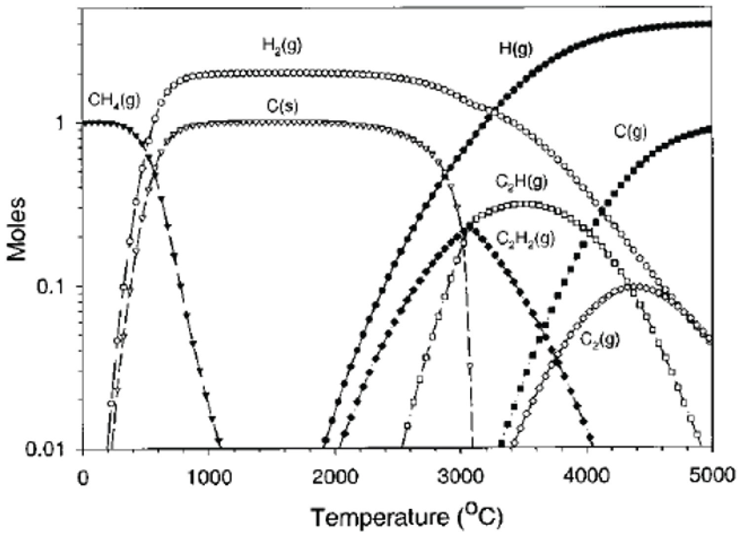
Figure 1: Simplified equilibrium diagram for....
Simplified equilibrium diagram for 1 mol of methane [27]-Reprint.

Figure 2: Spectroscopy of a plasma in the argon-methane.....
Spectroscopy of a plasma in the argon-methane mixture [36]-Reprint.
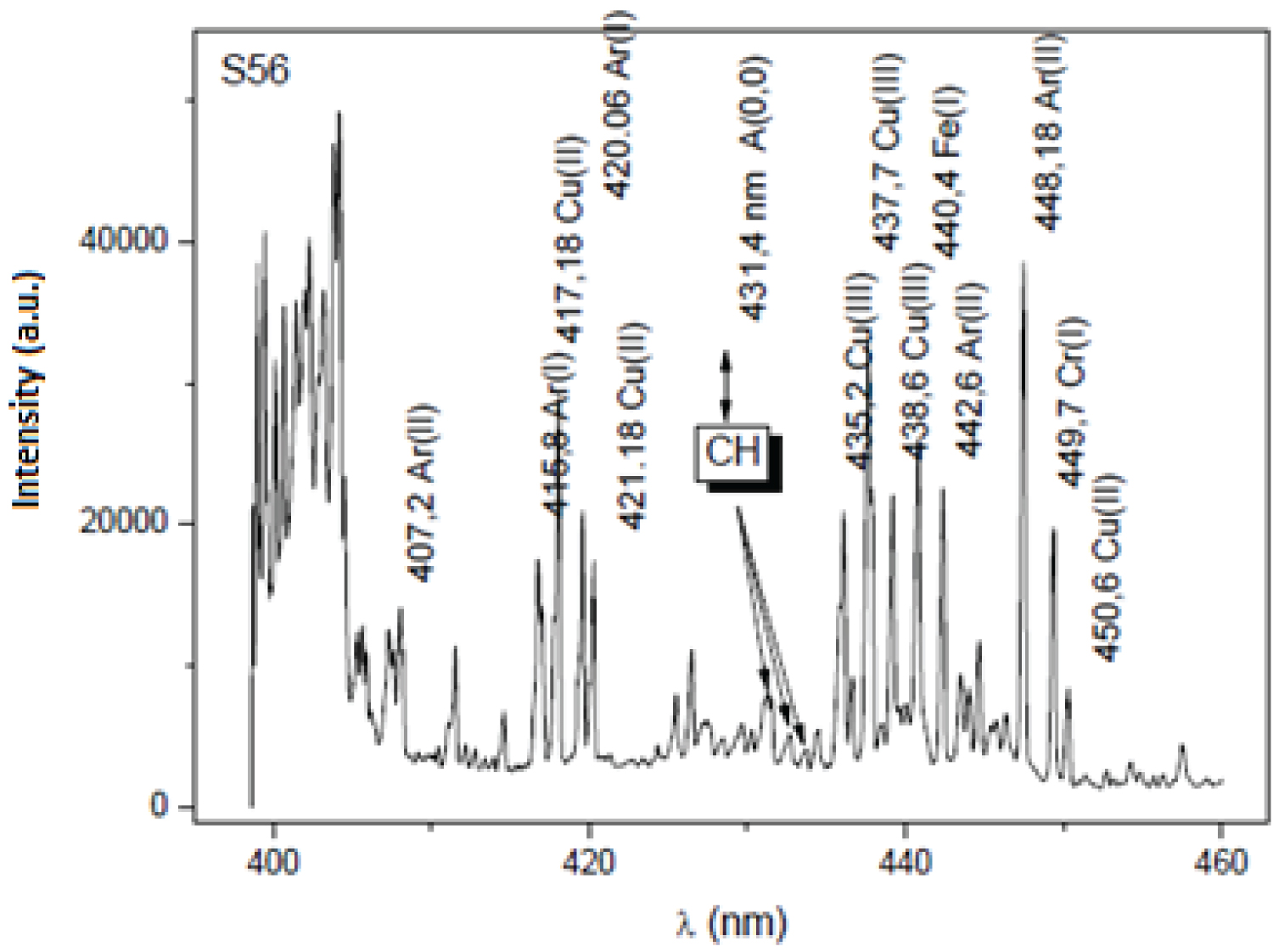

Figure 4: Laboratory plasma reactor in a non-transferred....
Laboratory plasma reactor in a non-transferred arc configuration [36].


Figure 6: Bottom of the three catalytic beds in the lower....
Bottom of the three catalytic beds in the lower flange of the reactor.

Figure 7: Photograph of laboratory reactor and an...
Photograph of laboratory reactor and an illustration of plasma reactor.
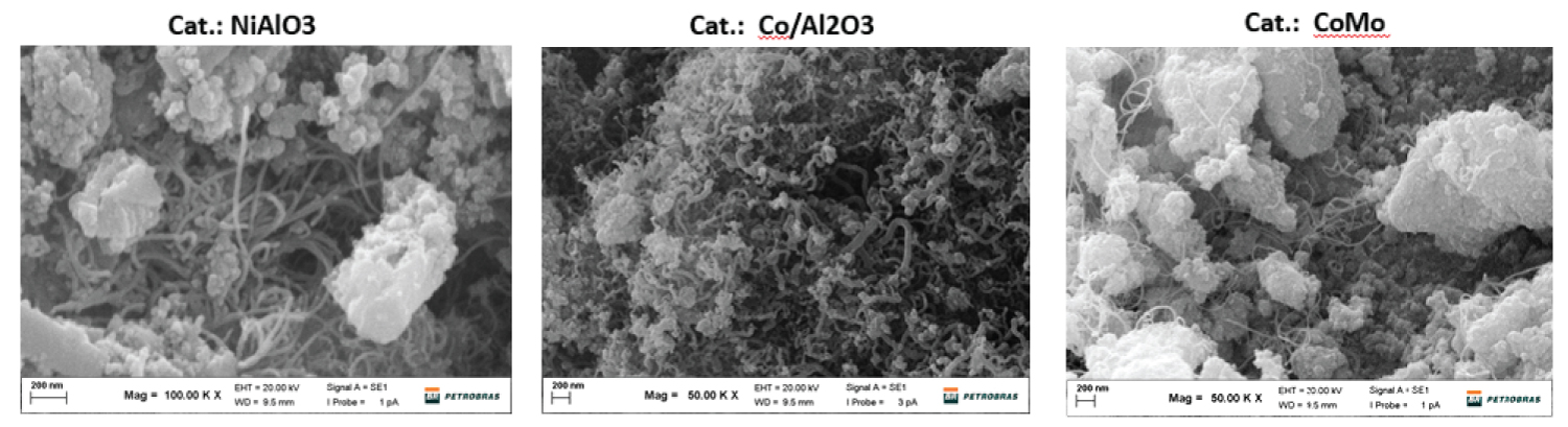
Figure 8: SEM images of samples of experiment...
SEM images of samples of experiment 2 (T2 ~ 720 ℃).
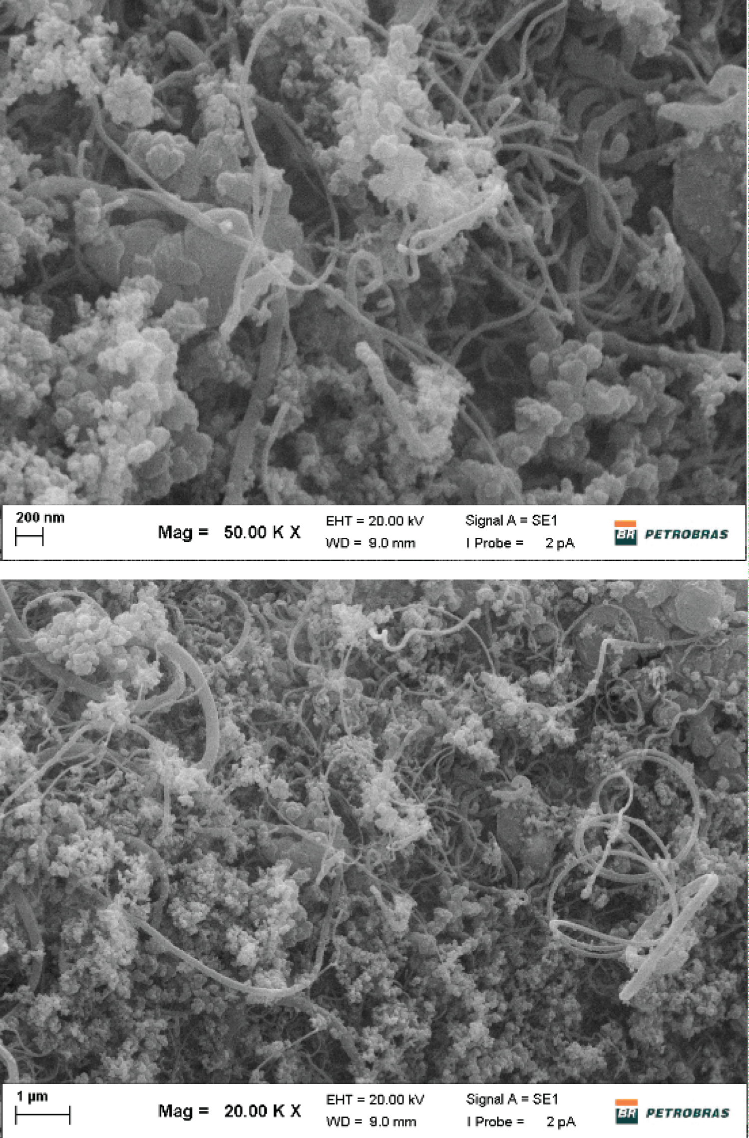
Figure 9: SEM images of sample of experiment....
SEM images of sample of experiment 2 referred to Co/Al2O3 catalyst.
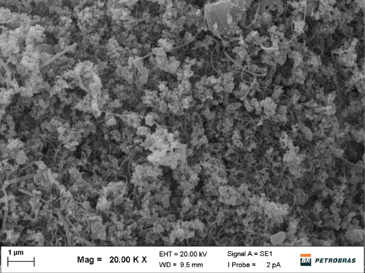
Figure 10: SEM image of sample of experiment...
SEM image of sample of experiment 2 referred to NiAlO3 catalyst.
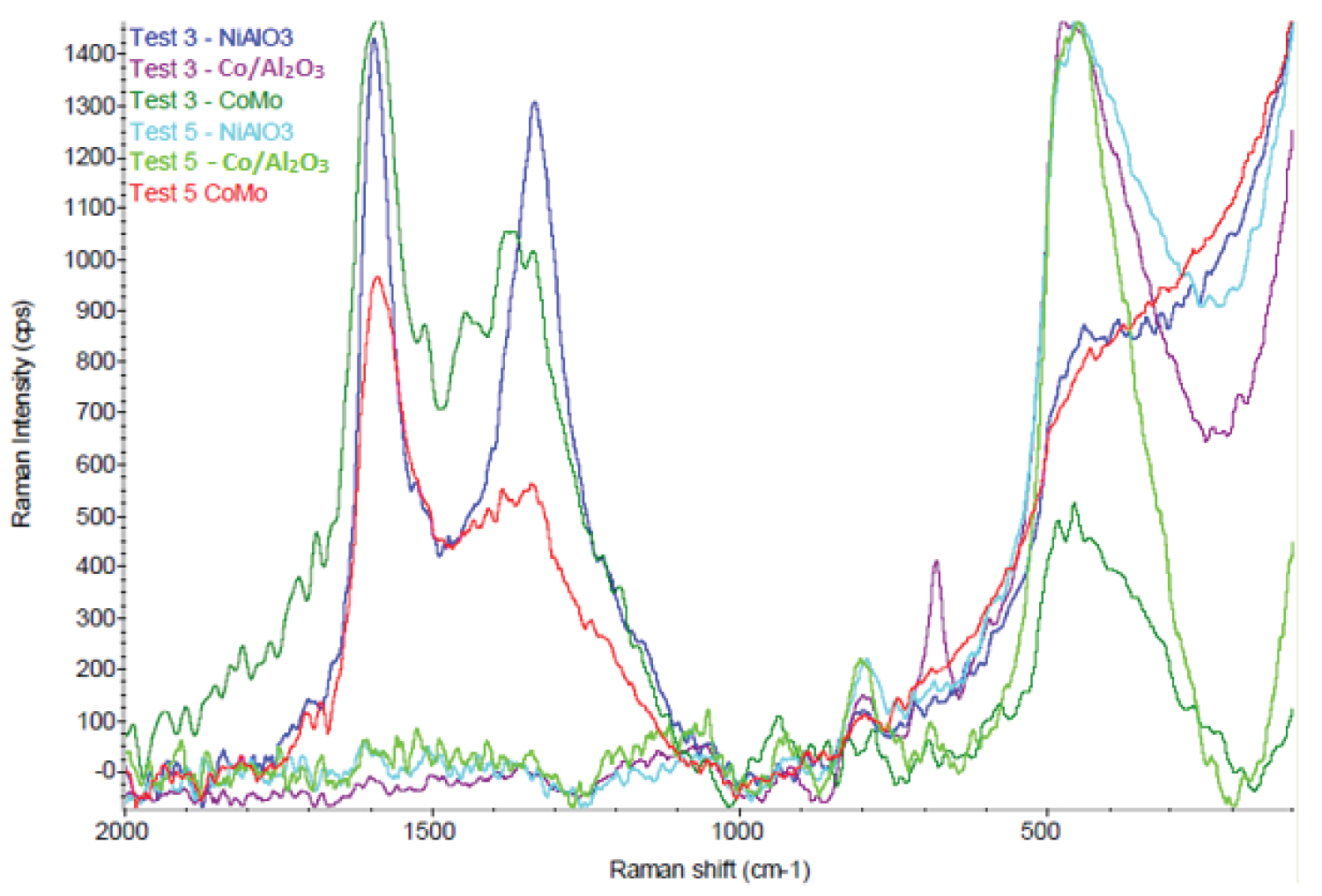
Figure 11: RAMAN spectra of raw soot produced...
RAMAN spectra of raw soot produced in experiments 3 and 5.
References
- M Kumar, Y Ando (2010) Chemical vapor deposition of carbon nanotubes: A review on growth mechanism and mass production. Journal of Nanoscience and Nanotechnology 10: 3739-3758.
- J Sengupta (2018) Carbon nanotube fabrication at industrial scale: Opportunities and Challenges. Department of Electronic Science, Jogesh Chandra Chaudhuri College, West Bengal, India.
- ML Terranova, V Sessa, M Rossi (2006) The world of carbon nanotubes: An overview of CVD growth methodologies. Chem Vap Deposition 12: 315-325.
- A Ilnicka, JP Lukaszewicz (2019) Alternative synthesis method for carbon nanotubes. WILEY-VCH Verlag GmbH & Co KGaA, Weinheim.
- A Szabó, C Perri, A Csató, G Giordano, D Vuono, et al. (2010) Synthesis methods of carbon nanotubes and related materials. Materials 3: 3092-3140.
- A Matyushov (2009) Growth of carbon nanotubes via chemical vapor deposition. NSF Summer Undergraduate Fellowship in Sensor Technologies (Physics)-Arizona State University.
- R Zhang, Y Zhang, F Wei (2017) Horizontally aligned carbon nanotube arrays: Growth mechanism, controlled synthesis, characterization, properties and applications Chem Soc Rev 46: 3661.
- R Zhang, Y Zhang, F Wei (2017) Controlled synthesis of ultralong carbon nanotubes with perfect structures and extraordinary properties. Acc Chem Res 50: 179-189.
- M Meyyappan (2005) NASA Ames Research Center, EUA. Carbon nanotubes science and applications. EDITED BY. CRC Press LLC.
- EC Neyts (2012) PECVD growth of carbon nanotubes: From experiment to simulation. Journal of vacuum science & technology B, 30.
- A Peigney, Ch Laurent, E Flahaut, RR Bacsa, A Rousset (2001) Specific surface area of carbon nanotubes and bundles of carbon nanotubes. Carbon 39: 507-514.
- A Mehrizad, M Aghaie, P Gharbani, S Dastmalchi, M Monajjemi, et al. (2012) Comparison of 4-chloro-2-nitrophenol adsorption on single-walled and multi-walled carbon nanotubes. Iranian Journal of Environmental Health Science & Engineering 9: 5.
- X Ren, C Chen, M Nagatsu, X Wang (2011) Carbon nanotubes as adsorbents in environmental pollution management: A review. Chem Eng Journal 170: 395-410.
- NT Abdel-Ghani, GA El-Chaghaby, FS Helal (2015) Individual and competitive adsorption of phenol and nickel onto multiwalled carbon nanotubes. Journal of Advanced Research 6: 405-415.
- SI Choi, JS Nam, CM Lee, SS Choi, JI Kim, et al. (2006) Hong high purity synthesis of carbon nanotubes by methane decomposition using an arc-jet plasma. Department of Nuclear Engineering, Seoul National University 6: 224-229.
- CJ Lee, J Park (2000) Growth model of bamboo-shaped carbon nanotubes by thermal chemical vapor deposition. Appl Phys Lett 77: 3397.
- R Purohit, K Purohitb, S Rana, RS Ranaa, V Patel (2014) Carbon nanotubes and their growth methods. Procedia Materials Science 6: 716-728.
- L Szymanski, Z Kolacinski, S Wiak, G Raniszewski, L Pietrzak (2017) Synthesis of carbon nanotubes in thermal plasma reactor at atmospheric pressure. Nanomaterials 7: 45.
- RH Amirov, EI Asinovsky, EKh Isakaev, VI Kiselev (2005) Thermal plasma torch for synthesis of carbon nanotubes. High Temperature Material Processes 10: 197-206.
- L Fulcheri, N Probst, G Flamant, F Fabry, E Grivei, et al. (2002) Plasma processing: A step towards the production of new grades of carbon black. Carbon 40: 169-176.
- MM Sahihazar, M Nouri, M Rahmani, MT Ahmadi, H Kasani (2018) Fabrication of carbon nanoparticle strand under pulsed arc discharge. Plasmonics 13: 2377-2386.
- KS Kim, JH Seo, JS Nam, WT Ju, SH Hong (2005) Production of hydrogen and carbon black by methane decomposition using DC-RF hybrid thermal plasmas. IEEE Trans Plasma Sci 33: 813-823.
- GASPLAS AS (2012) Method for processing a gas and a device for performing the method. United States Patent Application Publication. Publication Number: US 2012/0034135 A1.
- RK Amirov, IN Atamanuk, NA Vorobieva, EH Isakaev, MB Shavelkina, et al. (2015) Synthesis of graphene-like materials by pyrolysis of hydrocarbons in thermal plasma and their properties. Journal of Physics Conference Series 653: 012161.
- Lyten, Inc (2017) Microwave chemical processing United States patent. Publication Number US 9,767,992 B1.
- H Okuno, E Grivei, F Fabry, TM Gruenberger, JG Aguilar, et al. (2004) Synthesis of carbon nanotubes and nano-necklaces by thermal plasma process. Carbon 42: 2543-2549.
- RJ Fincke, RP Anderson, TA Hyde, BA Detering (2002) Plasma pyrolysis of methane to hydrogen and carbon black. Ind Eng Chem Res 41: 1425-1435.
- M Gautier, V Rohani, L Fulcheri (2017) Direct decarbonization of methane by thermal plasma for the production of hydrogen and high value-added carbon black. International Journal of Hydrogen Energy 42: 28140-28156.
- RI Rubel, Md H Ali, Md Abu Jafor, Md Mahmodul Alam (2019) Carbon nanotubes agglomeration in reinforced composites: A review. AIMS Materials Science 6: 756-780.
- S Laurenzi, F Zaccardi, M Semeraro, MG Santonicola (2018) Nanocomposite layers for spacecraft protection: From multiscale numerical model to experimental data. ECCM18-(18th edn) European Conference on Composite Materials Athens, Greece, 24-28th June 1 S.
- S Laurenzi, M Clausi, F Zaccardi, U Curta, MG Santonicola (2019) Spray coating process of MWCNT/epoxy nanocomposite films for aerospace applications: Effects of process parameters on surface electrical properties. Acta Astronautica 159: 429-439.
- (2020) NASA exploring using carbon nanotube for aerospace applications.
- A Golshahr, E Natarajan, MS Santhosh, R Sasikumar, S Ramesh, et al. (2018) Multi wall carbon nanotube reinforced silicone for aerospace applications. International Journal of Mechanical and Production-Engineering Research and Development 8: 775-784.
- S Bellucci, C Balasubramanian, P Borin, F Micciulla, G Rinaldi (2007) CNT composites for aerospace applications. Journal of Experimental Nanoscience 2: 193-206.
- P Kumari (2016) Development of smart composite for aerospace applications using MWCNT-CNF. IOSR Journal of Mechanical and Civil Engineering 13: 49-53.
- Labanca ARC (2007) Development of a plasma pyrolysis reactor for the decomposition of methane into hydrogen and carbon. Doctoral thesis, Universidade Federal do Rio de Janeiro, COPPE, Rio de Janeiro, 105.
- ARC Labanca, L Nachez, JN Feugeas, PEV Miranda (2007) Procesamiento de metano mediante pirólisis a plasma para producción de hidrógeno y carbono. Conamet/SAM-Mexico.
- C Zhang, S Zhang, Q Wang (2016) Bonding-restricted structure search for novel 2D materials with dispersed C2 dimers. Scientific Reports 6: 29531.
- YS Kim, JH Lee, YD Kim, SK Jerng, K Joo, et al. (2013) Methane as an effective hydrogen source for single-layer graphene synthesis on Cu foil by plasma enhanced chemical vapor deposition. Nanoscale 5: 1221-1226.
- SH Chan, SF Liao, HP Chen, HS Wei, SH Chen, et al. (2015) Spectral monitoring CH/C2 ratio of methane plasma for growing single-layer graphene on Cu. Hindawi Publishing Corporation. Journal of Nanomaterials 2015: 5.
- K Miyamoto, S Narita, Y Masumoto, T Hashishin, MK Masahito Ochiai, et al. (2020) Room-temperature chemical synthesis of C2.
- DM Gruen (1999) Nanocrystalline diamond films. Annual Review of Materials Science 29: 211-259.
- SH Chan, SF Liao, HP Chen, HS Wei, SH Chen, et al. (2015) Spectral Monitoring CH/C2 Ratio of Methane Plasma for Growing Single-Layer Graphene on Cu. Journal of Nanomaterials 2015: 5.
- V Ivan, M Regmi, P Fulvio, S Dai, P Datskos, et al. (2011) Role of hydrogen in chemical vapor deposition growth of large single-crystal graphene. ACS Nano 5: 6069-6076.
- Universidade Federal do Rio de Janeiro, PEV Miranda, ARC Labanca, JN Feugeas (2003) Reformador pirolítico a plasma para a decomposição de hidrocarbonetos ou álcoois em hidrogênio e carbono sólido.
- VZ Baldissarelli, LO de B Benetoli, FA Cassini, IG de Souza, NA Debacher (2014) Plasma-assisted production of carbon black and carbon nanotubes from methane by thermal plasma reform. J Braz Chem Soc 25: 126-132.
- M Moreno-Couranjou, M Monthioux, J Gonzalez-Aguilar, L Fulcheri (2009) A non-thermal plasma process for the gas phase synthesis of carbon nanoparticles. Carbon 47: 2310-2321.
- F Frédéric, G Flamant, F Laurent (2001) Carbon black processing by thermal plasma. Analysis of the particle formation mechanism. Chemical Engineering Science 56: 2123-2132.
- AM Cassell, JA Raymakers, J Kong, H Dai (1999) Large scale CVD synthesis of single-walled carbon nanotubes. J Phys Chem B 103: 6484-6492.
- T Yanase, T Miura, T Shiratori, M Weng, T Nagahama, et al. (2019) Synthesis of carbon nanotubes by plasma-enhanced chemical vapor deposition using fe1-xmnxo nanoparticles as catalysts: How does the catalytic activity of graphitization affect the yields and morphology? Journal of Carbon Research 5: 46.
Author Details
A Labanca1*, C Silva2 and L Sacorague1
1Petrobras/Cenpes, Rio de Janeiro, Brazil
2SENAI, Natal, Brazil
Corresponding author
A Labanca, Petrobras/Cenpes, Rio de Janeiro, Brazil.
Accepted: December 02, 2020 | Published Online: December 04, 2020
Citation: Labanca A, Silva C, Sacorague L (2020) Atmospheric Plasma for Carbon Nanotubes Production. Int J Astronaut Aeronautical Eng 5:042.
Copyright: © 2020 Labanca A, et al. This is an open-access article distributed under the terms of the Creative Commons Attribution License, which permits unrestricted use, distribution, and reproduction in any medium, provided the original author and source are credited.
Abstract
This article presents preliminary results of methane pyrolysis in an argon thermal plasma reactor using catalysts as an alternative method for carbon nanotubes synthesis. Inside the reaction chamber located downstream of the plasma discharge, three different types of catalysts were tested simultaneously to analyze the formation of carbon nanotubes (CNTs) at atmospheric pressure and under different conditions of operation. The method considered here can be regarded as a variation of the Chemical Vapor Deposition (CVD), the most used method. In the present case, the CVD process is aided by electrical discharges in the ionization of a carrier gas as a way of supplying energy to the process and for this reason it is also known as Plasma Enhanced Chemical Vapor Deposition (PECVD). This article cites some advantages of the proposed method in the evaluation of it as a possible technique for carbon nanotubes production on a commercial scale.
Introduction
CNTs are characterized by their unique structural morphology, as they are made up of cylinders of nanometric diameters formed by well-organized carbon atoms, resembling graphene's rolled around the axis of symmetry. They can be Single-Walled (SWCNTs), as well as Double-Walled (DWCNTs), Triple (TWCNTs) or multiple concentric nanotubes (Multi-Walled CNTs - MWCNTs).
The physical properties of CNTs are extraordinary due to this nanometric organization. Depending on even more subtle features, such as the arrangement of carbon atoms in the nanotube's own network, the CNTs has highly different potentials in their properties. Possibly the best example in this sense, is the electrical conductivity of a CNT that strongly depends on the crystalline orientation of the carbon network in the CNT itself.
Usually, carbon nanotubes are formed in a grouped manner without chemical bonds between them and can be aligned or entangled, which depends on their growth mechanism. CNTs clusters are formed due to van der Waals force. Their morphological characteristics are not identical among the CNTs present in the same mass of carbonaceous materials.
CNTs require sophisticated production processes and the effort to develop reactors for the synthesis of large-scale carbon nanomaterials has been undertaken by several research groups. The properties of CNTs are remarkable, however, to fully exploit the potential shown, production methods need to be further refined to obtain large amounts of CNTs with the desired final morphological characteristics.
Despite enormous progress in the research of Carbon Nanotubes synthesis over the years, there is still no efficient way to produce CNTs with well-defined properties in large quantities with an economical technique [1]. The root of this problem is the lack of an adequate understanding of the CNT growth mechanism [1,2].
The basic methods most widely used for the synthesis of carbon nanotubes are Chemical Vapor Deposition (CVD), electric arc discharge and laser ablation [2-6]. Of these, CVD approaches have emerged as the most promising among the proposals to synthesize carbon nanotubes in order to achieve the goal of mass production [1,3,6].
Fei Wei and colleagues pioneered the controlled synthesis of defect-free ultralong CNTs by CVD. They synthesized half-meter Horizontally Aligned Carbon Nanotubes (HACNTs) with perfect structures [7,8]. According the group, the grow of ultralong CNTS can be regards as a probability event that if the catalysts can keep active enough during the whole CNT growth process.
Generally, SWCNTs have been reported with diameters between 0.4 nm to 3.0 nm [9]. The smallest innermost tube in a MWCNT was found to be as small as 0.4 nm. Typically, MWCNT diameter is larger than 2 nm inside and smaller than 100 nm outside [9]. SWCNT diameter does not necessarily follow the diameter of the particle, which in general is nonspherical [10]. Table 1 shows some typical characteristics of SWCNTs and MWCNTs.
The Specific Surface Area (SSA) of CNTs depends mainly on the number of walls, in addition to the diameter of the CNTs and the size of the bundles. Because each addition of the wall does not cause a strong increase in the CNT surface area, but causes a much larger increase in its weight [11]. Thus, bundles of MWCNTs usually have smaller SSA than bundles of SWCNTs, than bundles of DWCNTs and even of TWCNTs.
Despite the fact that SWCNTs have a higher specific surface area than MWCNTs [11,12], MWCNTs have three possible sites for adsorption including external surface, inner cavity and interwall spaces, while SWCNTs have only two possible sites including external surface and inner cavity [12,13]. MWCNT offer a highly effective adsorbent that can be applied to wastewater treatment systems [14].
SWNTs are promising in electronic applications, since they can be either metallic or semiconducting, depending on their chirality and diameter [10]. The thermal conductivity of SWCNTs is about three times higher than that of diamond [7].
Even CNTs containing some structural defects and with non-uniform morphological characteristics due to the mixture of different types of CNTs in a bulk of carbonaceous materials, they are interesting in several applications, such as effective adsorbents for wastewater treatment [9,10,12-14] and as filling agents of different materials forming multifunctional nanocoposites for different purposes. Although CNTs of different characteristics exist in the same bundle, filling matrices with these arrangements adds new and highly relevant functions to the nanocoposites formed for the final application, for example, improving electrical and/or thermal conductivity.
CNTs synthesis
In arc discharge technique an electric arc formed between electrodes is used for sublimation of graphite [2] and it has been widely used for the CNTs synthesis since it can produce highly crystallized CNTs by high temperature (about 5000 K) [15]. However, it is still difficult to adapt the conventional arc discharge method to commercial use due to its low purity disadvantages, in addition to not being a continuous process. In case of the laser ablation technique an ablation induced by a laser is used for sublimation of graphite as a target.
However, both laser ablation and arc discharge have major disadvantages; both methods require high purity graphite rods, consume large amounts of energy and have low yields [2]. Therefore, these methods are not commercially viable to scale up for carbon nanotube production at an industrial level. Secondly, CNTs grown by high-temperature methods are in highly twisted forms, assorted with unwanted species of carbon and metal. [2]. Thus, the grown nanotubes by those two methods are hard to clean, manipulate, and accumulate for construction of CNT based device architectures [2]. In other words, these two synthesis methods are not continuous and need to have a shutdown period of operations to reload new graphite electrodes (arc discharge) or new rods of graphite (laser ablation) and for the collection of carbonaceous products inside the devices [15].
The CVD method allows the use of hydrocarbons in various states (solid, liquid or gas) as a carbon source, which can be place inside the reactor or fed from outside [1]. Facilitates the use of various substrates and allows CNT growth in a variety of forms, such as powder, thin or thick films; also in different shapes: Aligned or entangled, straight, bamboo type or coiled nanotubes [1], or even enables a desired architecture of nanotubes on predefined sites of a patterned substrate, which proves the versatility of the method. It also offers better control on the growth parameters [1].
CVD is currently the most popular and widely used method because of its low set-up cost, high production yield and ease of scale-up [1]. In addition, it has the advantage that the growth of CNTs can be achieved with high purity and vertical alignment [16].
However, CNT synthesis by CVD involves many parameters such as carbon source, catalysts, substrates, temperature, pressure, gas-flow rate, deposition time, reactor geometry, growth dynamics and different experimental conditions [1,2]. Mass-produced CNTs usually contain catalyst particles or support materials as impurity. Post-deposition purification greatly reduces the CNT quality and final output [1].
The three main parameters that affect CNT growth in CVD are the hydrocarbon, catalyst and growth temperature [17]. Considering the same CVD method for CNT synthesis, using the same hydrocarbon as a carbon source and similar catalysts, it can be said that higher operating temperatures favor the formation of SWCNTs, while lower temperatures yield MWCNTs [17,18], this temperature difference can be about 250-300 K [17,18]. For example, according to Lukasz Szymanski CNT synthesis at atmospheric pressure by CVDs reactors takes place in the flow system of a noble gas in the range of temperature from 800 K to 1000 K for MWCNTs and from 1100 to 1250 K for SWNTs [18]. Indicating that SWNTs have a higher energy of formation [17].
The catalyst particle size is also important to influence the nanotube diameter [10,17]. Thin films of catalyst coated onto various substrates have also been proved successful in achieving uniform CNT deposits. In addition, the material, morphology and textural properties of the substrate greatly affect the yield and quality of the resulting CNTs [17].
Fei Wei and group to keep catalysts active longer used Fe as the catalyst, a mixture of hydrogen and methane as carbon source and trace amount of water as the grow enhancer, silicon wafer as flat substrate and the temperature was set in a range of 1000-1040 ℃. By controlling the growing conditions, the as-grown ultralong CNTs can be SWCNTs, double-walled CNTs (DWCNTs) and triple-walled CNTs (TWCNTs) [8]. By precisely controlling the operation temperature, they were able to improve the selectivity in terms of TWCNTs, DWCNTs or SWCNTs [8]. According to him, the tip-growth mode is more favorable than the base-growth for synthesizing ultralong CNTs with perfect structures due to the fact that they can get rid of the influence of substrates [7,8].
PECVD: A variation of the CVD approach is the use of plasmas as a means of supplying energy to the source of carbon to do the dissociation reactions, knowing as Plasma Enhanced Chemical Vapor Deposition (PECVD), which will provide the nucleation and growth of carbon nanotubes in flying or stabilized catalysts inside the plasma reactor chamber.
A PECVD method uses only one source of energy for simultaneously perform dissociation reactions of hydrocarbons and heating the catalysts [15,18]. In addition, a plasma reactor is easily scalable [15] and can be operate at atmospheric pressure, so the technique looks promising for large-scale commercial production of carbon nanotubes.
Methane gas is widely used as a carbon source for the production of carbon nanomaterials, other CNT precursors commonly used are ethylene, acetylene, benzene, xylene and carbon monoxide [1]. Graphite is the most commonly used solid source of carbon.
The methods that require the use of vacuum or high pressure are disadvantageous in relation to the methods of synthesis in the atmosphere pressure [19]. A very relevant difference between the thermal plasma torch and the classic arc process for carbon nanomaterials synthesis is that the carbon input rate is not limited to the erosion of electrodes but can be controlled completely independently [19].
The present work evaluates the methane pyrolysis in thermal plasma reactor as a way to produce large quantities of CNTs by a remote PECVD. An advantage of this method in relation to PECVD with low energy plasmas (ex.: Glow discharges) is the distance between the plasma and the catalysts, avoiding a strong interaction between ions and the growing CNTs, in addition to operation at atmosphere pressure.
In a simplified way, the pyrolysis (or thermal decomposition) of methane is describe by Equation 1.
CH4 + Energy* → C + 2 H2 (1)
The plasma is generated by an external source of energy, thus the hydrocarbon decomposition reactions are not thermally affected by their own reactions and the temperature inside the reaction chamber can be maintained at the desired operating point. The yield can be about 100% in conversion the carbon source in carbon products by plasma pyrolysis [20] and purity of carbon material is extremely high or even 100% if the reactor uses electrodes of carbon.
The development of plasma reactors allowed operating conditions that had not been exploited until then [20], due to the all thermal feature of these reactors, when the energy used in the process comes externally and not directly from the reactions [21]. As a result, several methods applying plasmas from different regimes in electrical discharge systems have been investigated in the production of high-quality carbon materials [19-26].
Fincke [27] conducted a detailed theoretical study of the plasma decomposition of methane molecules to carbon and hydrogen by kinetic model that includes the reaction mechanisms resulting in the formation of acetylene and heavier hydrocarbons through benzene and a model for solid carbon nucleation and growth. He did also experimental tests about methane plasma pyrolysis and a comparison the model to experimental results.
Although the equilibrium dissociation of methane in hydrogen and carbon becomes complete at 1000 ℃, as show in Figure 1, to produce high quality carbon materials, the process should preferably take place in the gas phase. The rate of formation of unsaturated hydrocarbons, mainly acetylene, ethylene and benzene, is much faster than the complete decomposition of methane [27].
The kinetically limited process consists of a nucleation step followed by mass growth, the formation of polycyclic aromatic hydrocarbons (PAH) is a major soot nucleation mechanism and the formation of benzene is a precursor to the formation of higher aromatics [28]. The PAHs increase in molecular weight by the addition of acetylene and become deficient in hydrogen through the abstraction of hydrogen from molecules by atomic hydrogen, leading to the formation of primary soot particles. Primary soot particles continue to grow through the decomposition of acetylene on their surfaces. Carbon particle formation can be seen as a continuous dehydrogenation process of a hydrocarbon and the thermodynamics drive the formation of C-C bondings at the expense of C-H bonds [28].
Carbon-based nanocomposite materials
CNTs synthesis on a large scale with uniform and well-defined characteristics is still a major challenge for research and development; On the other hand, even CNTs obtained today are widely studied as filler agent in different materials [29-35], forming Carbon-based nanocomposites, with superior electrical, thermal and mechanical properties than traditional materials and still with significant weight savings [31].
The homogeneous dispersion of tiny amounts of CNTS in polymers forms nanocomposites with multifunctional properties that can fully satisfy the lightweight requirement by replacing complex and heavier subsystems of a spacecraft [30]. An example is the use of CNTs as fillers of polymeric materials to mitigate the electrostatic discharge phenomenon due interaction between surfaces of a spacecraft with the surrounding charged particles in space environment that can induce catastrophic failures [30]. Nanocomposite coatings on typical membranes have useful properties such as thermal blankets and charging mitigations layers [31].
NASA computer modeling analysis has shown that composites using carbon nanotube reinforcements could lead to a 30% reduction in the total mass of a launch vehicle [32]. According to Golshahr, et al. MWCNT reinforcement considerably improved mechanical properties of silicone 40 elastomers, the tensile strength of the 5 wt% MWCNT/silicone composite is 26% higher than pure silicone, the compression strength and shore hardness also enhanced up to 20% and 60% respectively, in addition to other improvements in terms of mechanical properties over traditional silicone [33].
According to Gabriella Santonicola and colleagues nanocomposite material made of 1 wt% of SWCNTs dispersed in RTM6 epoxy resin satisfies the NASA requirements, because the volumetric resistivity undergoes a severe reduction, passing from the value of 1013 Ohm•cm for the neat resin to that of 104 Ohm•cm for the nanocomposite [30]. The same research group obtained a uniform surface of the nano-reinforced epoxy films at 1% by weight of entangled MWCNT on Mylar substrate, which is a material largely used in many spacecraft subsystem [31]. Another study indicates that the elaboration of a nanocomposite formed by the addition of 0.5% wt of CNT in A1 Resin provides a decrease in resistivity of the order of 103 in relation to the original resin [34].
Experimental Part
In the present work the energy for methane pyrolysis reaction is given by electrical discharges in argon, used here as the plasma gas. Our previous work with spectroscopy analysis of methane in an argon plasma arc detected the presence of C2 dimers as show in Figure 2 [36,37]. The C2 dimer can be considered as a prototype of nanoclusters or a structural unit, thus dimerization of carbon can be viewed as the first stage toward final crystallization [38]. It is well known that the C2 dimers are critical to the formation of various carbon materials during the plasma system [39-43].
The excitation of the atomic hydrogen detected in the spectrum of Figure 2 corresponds to the transition of the electron from n = 3 to n = 2 and is called H-alpha (H α) and emits a wavelength of approximately 656 nm [39]. This proves that hydrogen species are produced during the methane dissociation process into their active species (CHX < 4), assisted with the plasma [36,37,39]. Hydrogen is well known to affect the activation of CHX radicals into more active species [39,44]. Which is also corroborated by the spectrum of Figure 3 where the CH bands are visible in the region near 430 nm, confirming the CH4 dissociation model. This figure also shows spectra peaks corresponding to the volatilization of the metals used in the electrodes, copper, iron and chrome in the previous experimental apparatus with electrical discharges in the mixture of argon and methane gas [36].
As mentioned before, atomic hydrogen is fundamental in the dehydrogenation process and thus, in the formation of carbon particles. In this way, plasma plays an important role in the growth of carbon materials during the dissociation process of methane into species such as H, H2, CH3, CH2, CH, C2H4, etc., using methane as carbon and hydrogen sources and, therefore, there is no need to introduce H2 in the process by other way [39].
The hydrogen has dual role in carbon nanomaterials synthesis [40]: An activator of CHX radicals into more active species (CHX + H ↔ CHX-1 + H2) and an etching reagent in the removal of amorphous carbon as an unwanted element adhered to the carbon nanomaterial.
H α is formed when hydrogen is ionized and the peak intensity increases with the DC power [39] and thus the amount of H2 can be adjusted. Resuming, methane plasma generates hydrogen containing species as it decomposes into hydrogen and active species. The active species are HX, CX, and CHX radicals [40].
Argon thermal plasma reactor experiments
The importance of C2 dimers, atomic hydrogen and others actives species during the dissociation of methane molecules in the argon plasma and in the nucleation of the first carbon nanoparticles motivated the development of the atmospheric plasma reactor using argon as plasma gas for carbon nanotubes production [45].
The thermal argon plasma reactor using catalysts for nucleation and growth of carbon nanotubes can be consider a remote PECVD method. Operation condition at atmospheric pressure allows more collision events between active particles, generating a greater amount of these precursors and of carbon that can provide a denser and faster-growing production of carbon nanomaterials. While hydrogen can help in the volatilization of the amorphous carbon generated in the process, in order to increase the amount of carbon nanotubes in the soot formed. The large distance between the plasma region and the bed of catalysts avoids the possibility of bombarding CNTs by ions formed in the plasma.
In particular, an arc jet plasma or a thermal plasma reactor in a non-transferred arc configuration, Figure 4, that uses only one energy source for simultaneously perform dissociation reactions and heating the catalysts in a continuous flow regime at atmospheric pressure. In such configuration, all content required for CNTs synthesis may be introduced into the reaction chamber by a single nozzle. In our case, the only variable that not passed through the nozzle responsible for the plasma spray are the catalysts; in this present work it was selected the use of a fixed bed containing the catalysts inside the chamber.
Using a Remote plasma CVD an analytical correlation between the many variables involved in the formation CNTs can be establish to facilitate the understanding of the CNTs formation mechanism. The main objective was to evaluate the capacity of the reactor on large-scale production of CNTs.
As show in Figure 4, the gases (Ar and CH4) were introduced between electrodes in non-transferred arc configuration and water was used for cooling electrodes. The experiments related here makes a first analysis of carbon nanotubes formation by argon thermal plasma atmospheric reactor [45] as remote PECVD and an alternative technique to usual methods for CNTs synthesis.
The electrical arc between the cathode and the anode was initiated by a high voltage discharge generated by a continuous power source. In the evaluation of the fabricated reactor first methane pyrolysis was performed in argon plasma without catalysts obtaining Carbon Black (CB) and hydrogen. In this case, an additional amount of methane was introduced downstream of the plasma torch. The stream containing the reaction products, after retention of the solid material in filters, was analyzed by chromatography, which confirmed the presence of CH4, C2H2 and H2, corroborating the dehydrogenation process.
Figure 5 shows a SEM image of the CB produced when catalysts were not used as described above. After that, it was conducted the methane pyrolysis in argon plasma with the use of catalysts and less methane gas to be processed, CNTs were obtained as described at present article and also performed by other authors [18,46].
For the present investigation, three catalyst-containing beds were used inside the reaction chamber to be tested simultaneously. For obtaining CNTs it is important not to use excessive flow rate of CH4 as this reduces the purity of these in the soot [15], therefore, only the methane injection at the top was maintained as show in Figure 4.
The position of the catalyst bed relative to the plasma spray nozzle is of great importance in the formation of carbon nanotubes. Placement of catalysts too far cannot form CNTs, but CB, which are generally composed of small crystallites showing a turbostratic arrangement [47,48].
In the experiments the following catalysts were used: Co/Al2O3, NiAlO3 and a hydrogenation catalyst of CoMo, all with particle size between 115 (aperture: 125 µm) and 270 mesh (aperture: 53 µm). The catalysts were wrapped in a steel mesh and introduced into 10 cm vertical tubes made of copper. Figure 6 is a photograph of the bottom of the reaction chamber containing the vertical catalytic beds deflected at 120° relative to the other two. The adjacent drawing is a representation of the catalytic bed inside the copper tube, where T2 is the highest temperature at one end of this tube.
Figure 7 is a photograph of the argon thermal plasma reactor used in experiments related here. After insertion of the catalysts into the beds inside the reaction chamber, it was closed by a conical flange for the isolation of the oxygen from the atmosphere. The adjacent drawing is an illustration of the reactor with its main parts and location of the catalysts inside the chamber.
The Table 2 presents information about the operating conditions of the experiments described here. The argon was used as plasma gas, the methane gas flow here is much lower and remained between 5 to 15% of the volume of argon flow. The introduction of larger amounts of methane generates excess carbon within the system and does not aid in the evaluation of CNTS formation. In previous experiments at low pressure [36], volumetric flows of methane introduced between the electrodes and above 25% of the argon flux caused the electric arc to extinguish. The electrodes used in the experiments described here are made mainly of copper and erosion of the cathode was fast. The electrodes were tested for about 12 hours and the table refers only to experiments carried out with catalysts and at the end of the cathode's useful life. The operation temperature was controlled by the intensity of the current applied by the power source.
The objective of this work is to evaluate the atmospheric argon thermal plasma enhanced CVD in a non-transferred arc configuration capacity to produce carbon nanotubes on a large scale, in addition to a simple comparison between the catalysts tested to help the formation of carbon nanotubes at different temperature ranges in that specific plasma reactor. The results were used to design a new plasma torch electrode with stronger and more efficient materials for converting electrical energy to thermal energy.
In order to observe the samples in the Scanning Electron Microscope (SEM), each of them was deposited on a carbon-conductive adhesive label placed on a slide, which was then covered by a thin layer of Au/Pd, through the EMITECH K750X metallizer. In order to make it also conductive, it was adhered in aluminium conductive support and thus the sample was analyzed in the Scanning Electron Microscope ZEISS EVO LS-15, in images by secondary electrons, operating in a high vacuum at 15 kV and with working distance of 10 mm.
The structural nature of carbon is best characterized by RAMAN spectroscopy, which was applied to samples from experiments 3 and 5, according to the type of catalyst used. The samples from Experiment 4 were not analyzed. For the analysis of these samples, a RAMAN Thermo Fisher spectrometer, model Smart Raman DXR, was configured with an excitation laser that emits at 532 nm.
Results and Discussion
The analysis of the samples of Experiment 2 in the SEM showed that almost all catalysts (Co/Al2O3, NiAlO3 and CoMo) presented carbon deposits with several types of morphology, such as filamentous, nanostructured and Multi-walled carbon nanotubes (MWCNTs). Figure 8 shows SEM images for each type of catalyst tested in Experiment 2. In Experiment 2, the following yields (%wt) in the production of carbon nanomaterials were obtained: With CoMo equal to 87%, with Co/Al2O3 equal to 85% and with NiAlO3 equal to 56%. These values were obtained by averaging along the vertical catalytic bed containing the carbonaceous materials.
Figure 9 presents SEM images with different magnitudes (50.000 X and 20.000 X) for the same sample collected referring to the cobalt based catalyst (Co/Al2O3). It is possible to note the presence of coiled nanotubes, as well as CNTs of different diameters in the middle of the soot formed by CB.
Figure 10 shows a SEM image of the carbonaceous materials formed in the Experiment 2 with the NiAlO3 catalyst. Note the presence of CNTs in a large amount of CB. It can inferred that the amount of methane used as a carbon source was excessive under the conditions of Experiment 2.
The catalysts were inserted loose inside the steel screen housed into the bed tubes, this favoured the formation of relatively long entangled CNTs via tip-growth mode, since the catalysts were not on a fixed substrate. The introduction of the catalysts in these tubes causes inhomogeneity of the material, since the temperature conditions are different along the vertical tube. It was obtained entangled CNTs of different diameters with lengths up to 20 µm or even longer and a large amount of amorphous carbon.
The analysis of the samples of Experiments 3 and 5 (Test 3 and Test 5 in (Figure 11) were made in RAMAN spectroscopy as show in Figure 11. The carbonaceous material formed in Experiment 4 was not analyzed.
It is well known that the band around 1585 cm-1 (G Band) is characteristic of graphite structures, the band at 1330 cm-1 (D Band) normally is associated with "defects" in these structures. Presence of amorphous carbon identified at 470 cm-1.
In experiments 3 and 5, no carbon nanostructures were produced for the Co/Al2O3 catalyst. This type of catalyst performed well only at high operating temperatures, as can be seen in Figure 9 (T2 ~ 720 ºC). For temperatures T2 ~ 500 ℃, under the conditions of Experiment 3, only NiAlO3 and CoMo catalysts formed carbon nanostructures. In the conditions of experiment 5, for lower operating temperatures (T2 ~ 380 ℃), only CoMo was able to assist in the production of carbon nanostructures confirming the additional advantage of using bimetallic catalyst [49] to obtain CNTs at lower temperatures [1]. It should be noted that in the experiment 5, the formation of carbonaceous materials occurred in only about 50% of the tube's axis.
From the results presented, it can be inferred that the amount of methane used as a carbon source was excessive, forming a large amount of amorphous carbon. The proportion (source of carbon/plasma gas) closest to the ideal is that conducted in Experiment 3; with intermediate temperatures (T2 ~ 500 ℃) and with less methane, generating less amount of amorphous carbon.
The quality of CNTs can be evaluated by the intensity ratio of D peak (ID) and G peak (IG) because the G band (1585 cm-1) is assigned to the intrinsic vibrational mode of CNT, while the D band (1330 cm-1) is assigned to the defect mode [50]. ID/IG was calculated as 0.7 for sample CoMo in experiment 3, which is can considered CNT with high quality [50]. For sample NiAlO3 in Experiment 3 the ratio ID/IG is about 0.92.
The process can be improved through greater control of variables, also using traces of water as growth enhancers for CNTs to keep catalysts active for longer [7,8]. Another improvement can be analyzed by adopting a horizontal catalytic bed in order to reduce the temperature gradient over it. Another suggestion is to improve the formulation of the catalyst, with a focus on increasing the dispersion of the active phase on a support, seeking the formation of particles with smaller diameters. Operation at higher temperatures may favor obtaining SWCNTs.
Conclusions
A remote plasma CVD as that used in the developed argon thermal plasma reactor can operate in a continuous flow regime, atmospheric pressure and unifies several process variables involved in the production of CNTs when almost of them passing through a single nozzle. The plasma spray, the thermal energy, the argon and the methane gas are responsible for all active species that can be analytically grouped by computational simulation of the flow in the channel and inside the reactor. It has only one source of energy for simultaneously heating the catalysts and breaks the chemical bonds of the gases. In addition, there is a gap between the active species in the plasma and the catalysts inside the reaction chamber, which facilitates laboratory observations on this free path and avoids the possibility of bombarding CNTs by plasma ions.
CNTs were obtained in the reactor developed using the three different catalysts tested (Co/Al2O3, NiAlO3 and CoMo). CoMo, as bimetallic catalyst, was the only one that allowed the formation of carbon nanostructures for low temperatures (T2 ~ 380 ℃), which was possible only because methane was partially decomposed by plasma. Thus, carbon nanostructures were obtained in the reactor over a wide temperature range of around 340 ℃, which can be further explored, using high operating temperatures. There is a large useful volume inside the reaction chamber due high-energy plasma and that can be used for the production of carbon nanotubes on commercial scale.
For high operating temperatures, the reactor can be used to make CNTs as a function of the temperature gradient inside chamber reaction. The catalysts can be better distributed throughout the chamber, producing carbon nanotubes under different temperature conditions and with different morphologies depending on local temperature, catalysts and substrates characteristics, in addition to the flow conditions.
The possibility of CNTs synthesis was confirmed in the experiments, indicating that the thermal PECVD method using argon can be used to produce CNTs on a large scale, directly dependent on the amount of methane processed, the plasma intensity and catalysts. The process can be improved through greater control of the operational parameters and the use of traces of water to keep the catalysts active for longer.
Acknowledgements
Thanks to PETROBRAS, to Brazilian National Electric Energy Agency (ANEEL) for supporting the project PD-00553-0057/2018 for the production of hydrogéné and carbon nanostructured by plasma. Thanks to the Brazilian National Petroleum Agency (ANP) for supporting that project in the past. Thanks to colleagues at PETROBRAS Cristina Pontes Bittencourt Quitete and Ailton Luis da Silva de Souza for the SEM images.