
International Journal of Astronautics and Aeronautical Engineering
(ISSN: 2631-5009)
Volume 6, Issue 2
Original Article
DOI: 10.35840/2631-5009/7553

Article Formats
Energy and Exergy Analysis of a Closed Brayton Cycle for Power Generation from the Scramjet Cooling Heat
Table of Content
Figures
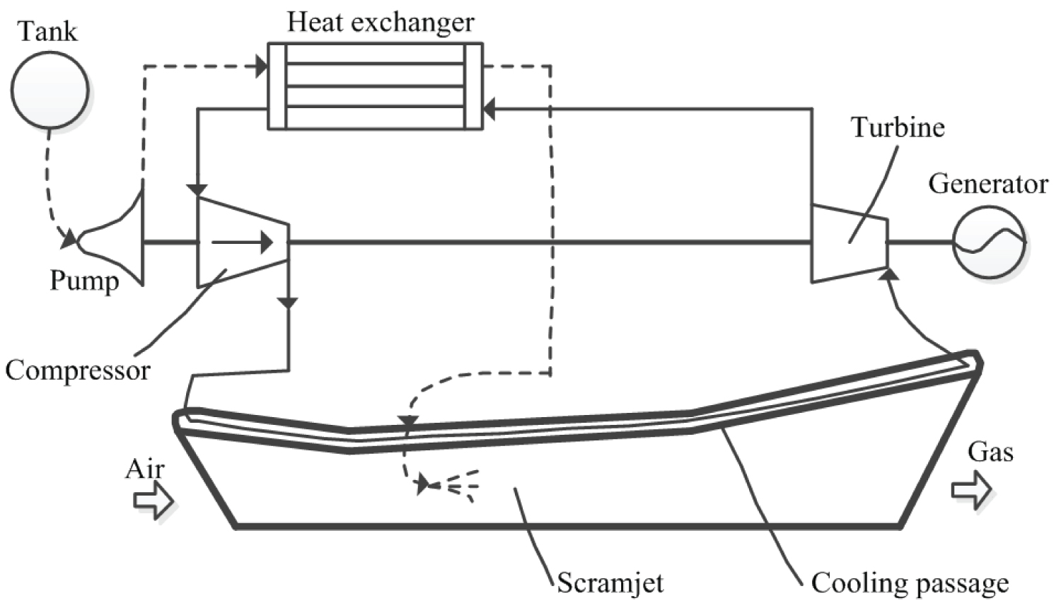
Figure 1: The conceptual scheme of power...
The conceptual scheme of power generation system for scramjet based on CBC.

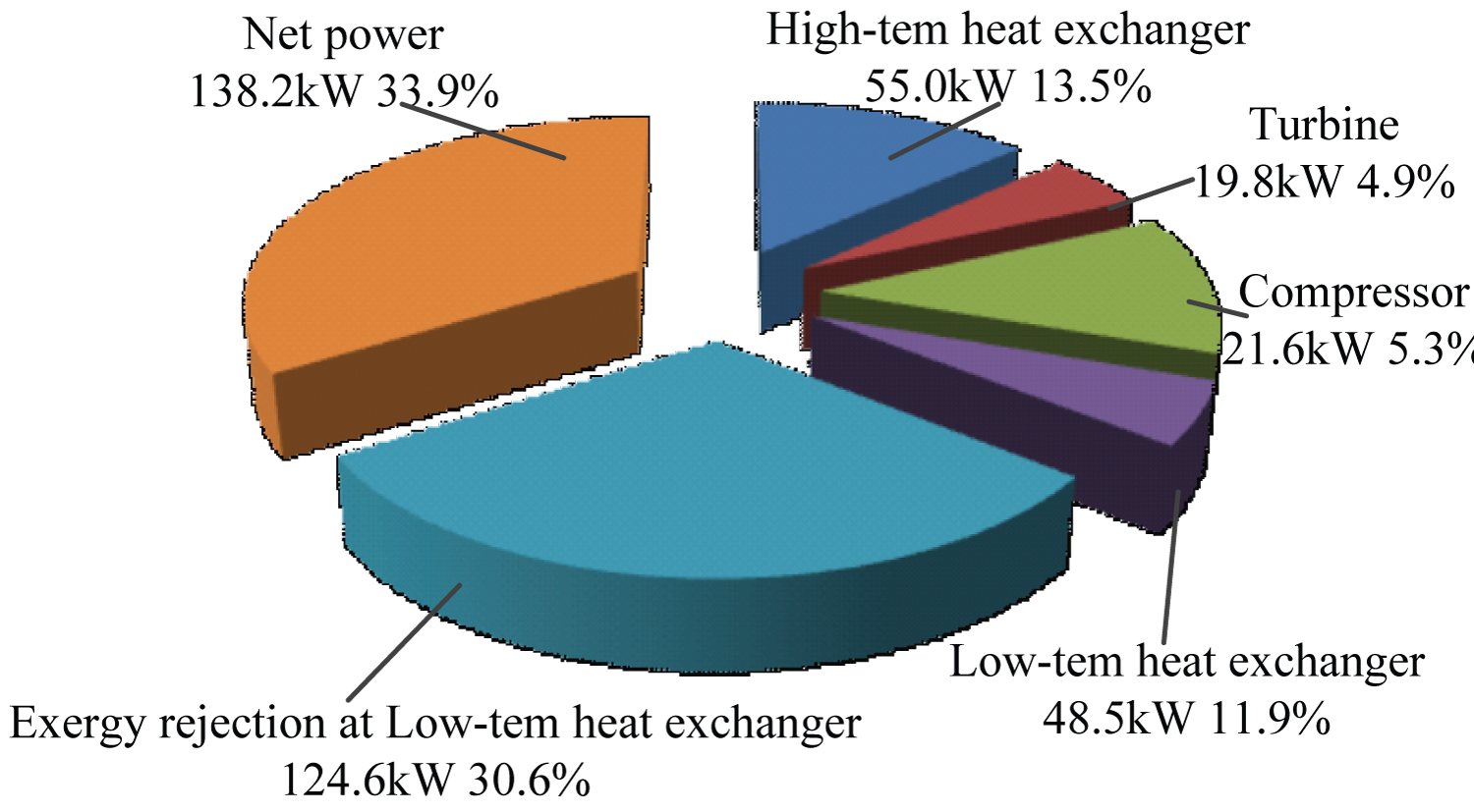
Figure 3: Exergy losses diagram and given....
Exergy losses diagram and given as the percentages of exergy input.
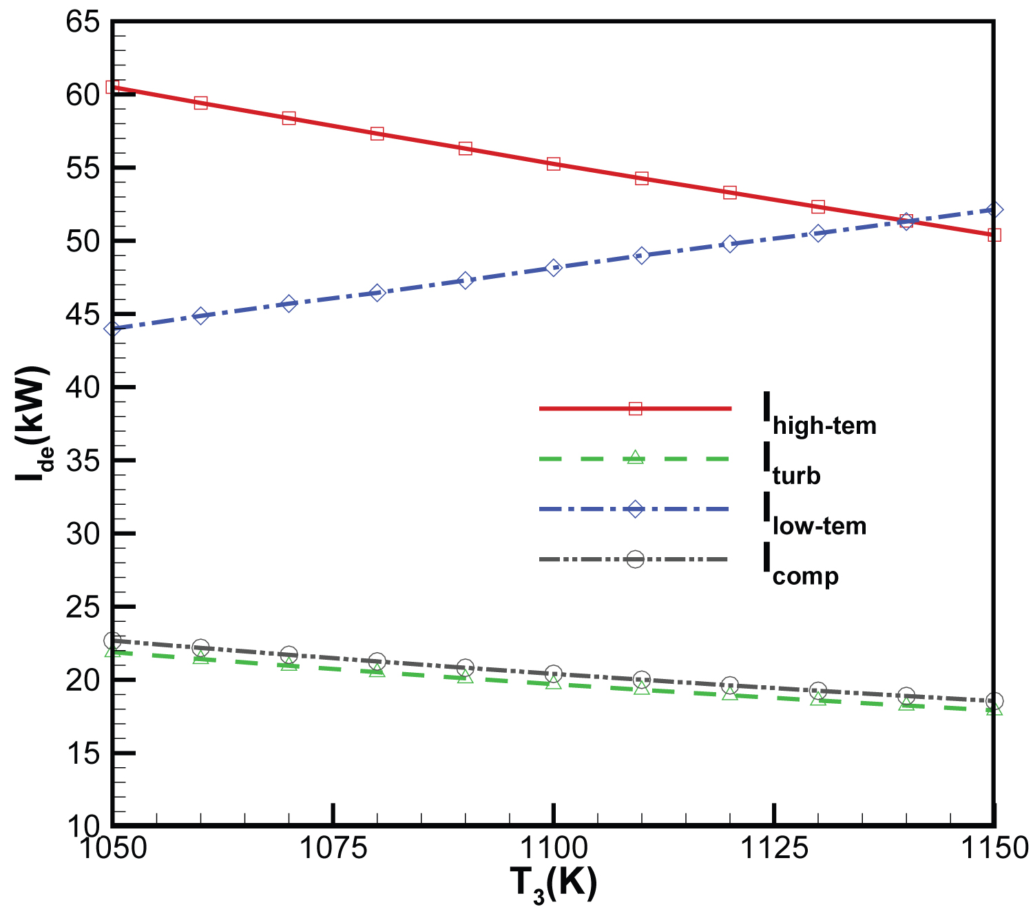
Figure 4: Variation of components irreversibility's....
Variation of components irreversibility's with high-temp heat exchanger outlet working fluid temperature.
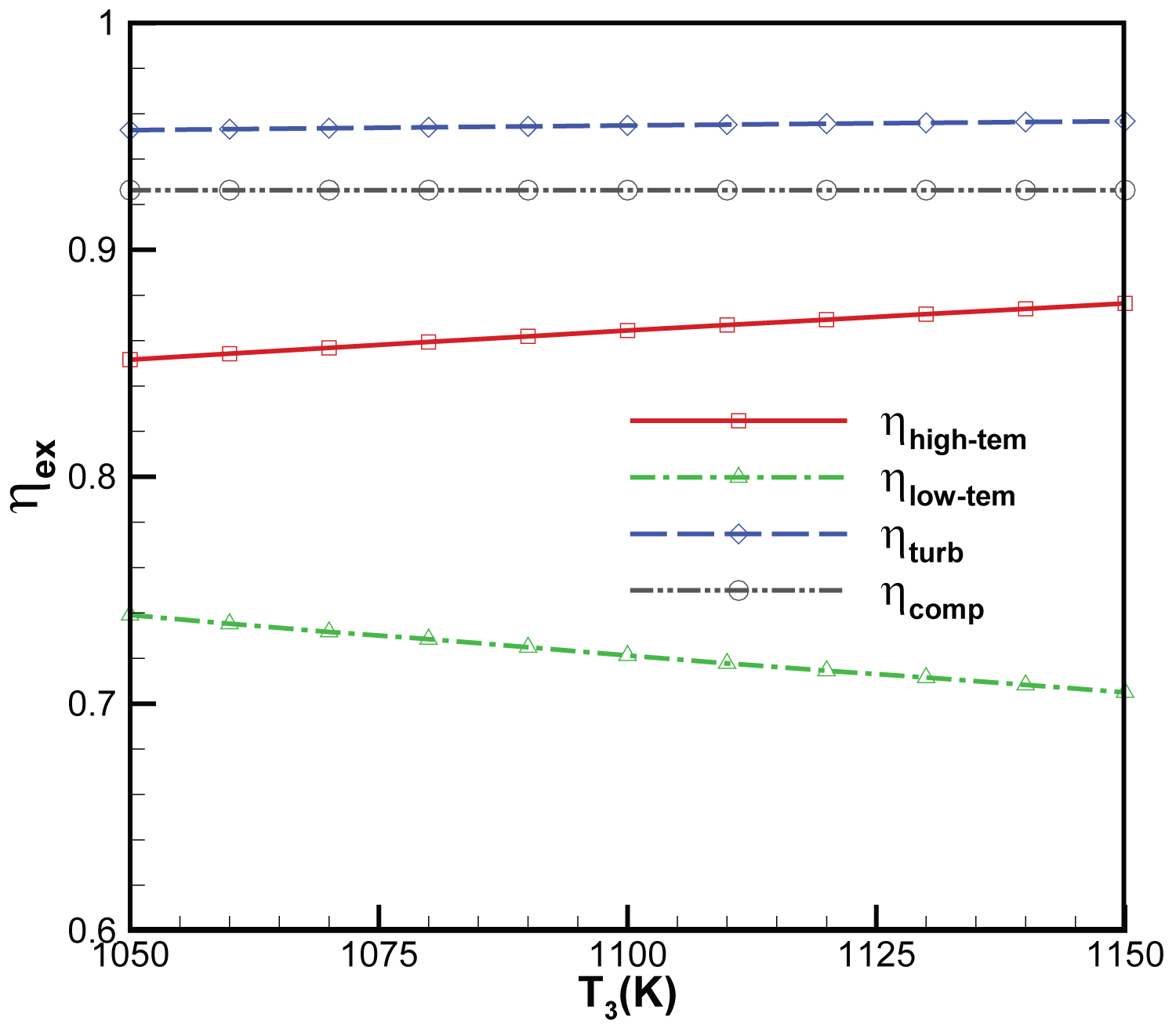
Figure 5: Variation of components exergy efficiency....
Variation of components exergy efficiency with high-temp heat exchanger outlet working fluid temperature.
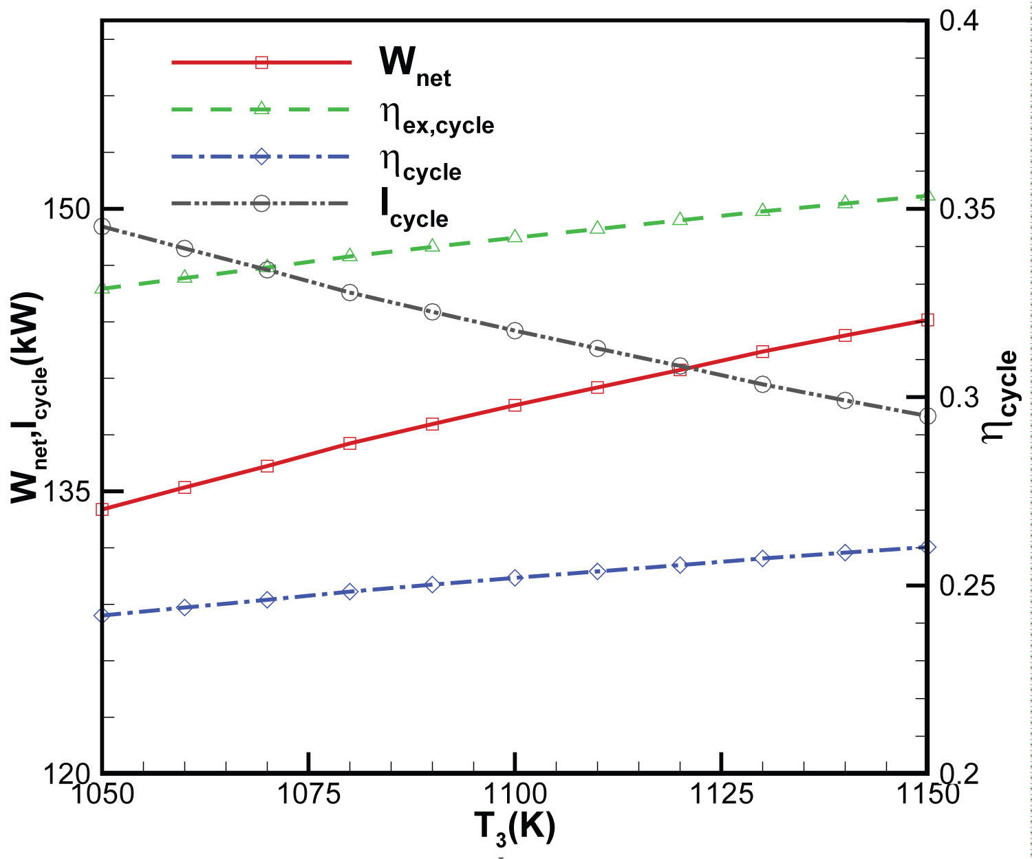
Figure 6: Variation of net power, exergy....
Variation of net power, exergy and energy efficiency of the cycle, irreversibility's of the cycle with high-temp heat exchanger outlet working fluid temperature.
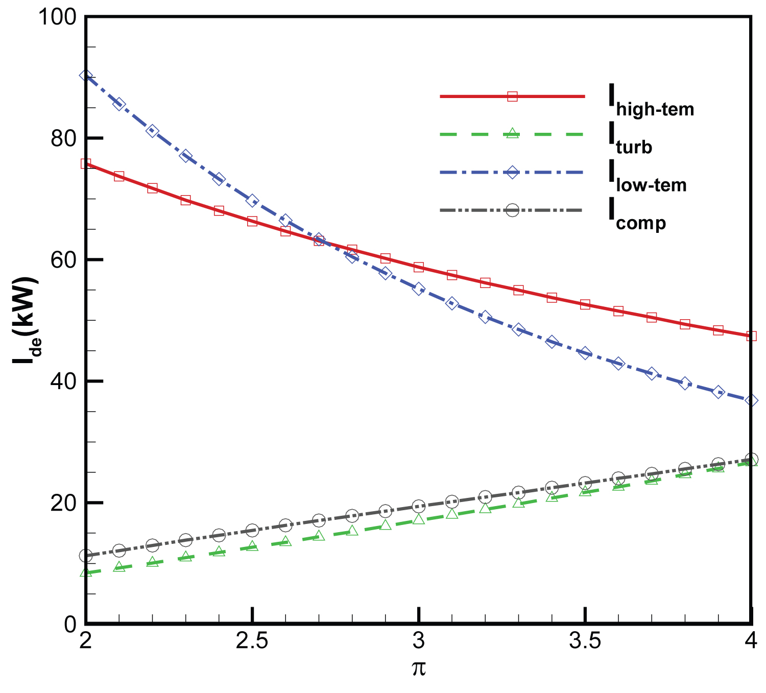
Figure 7: Variation of components irreversibility's...
Variation of components irreversibility's with pressure ratio of the cycle.
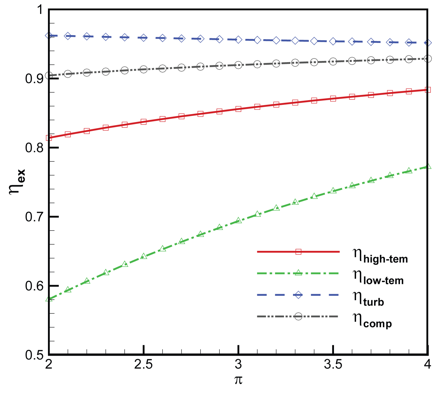
Figure 8: Variation of components exergy...
Variation of components exergy efficiency with pressure ratio of the cycle.
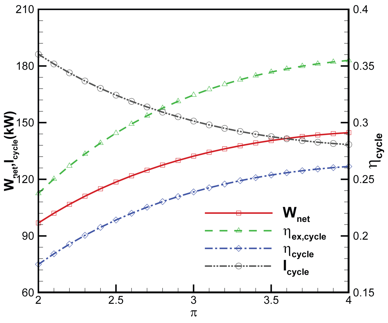
Figure 9: Variation of net power, exergy...
Variation of net power, exergy and energy efficiency of the cycle, irreversibility's of the cycle with pressure ratio of the cycle.
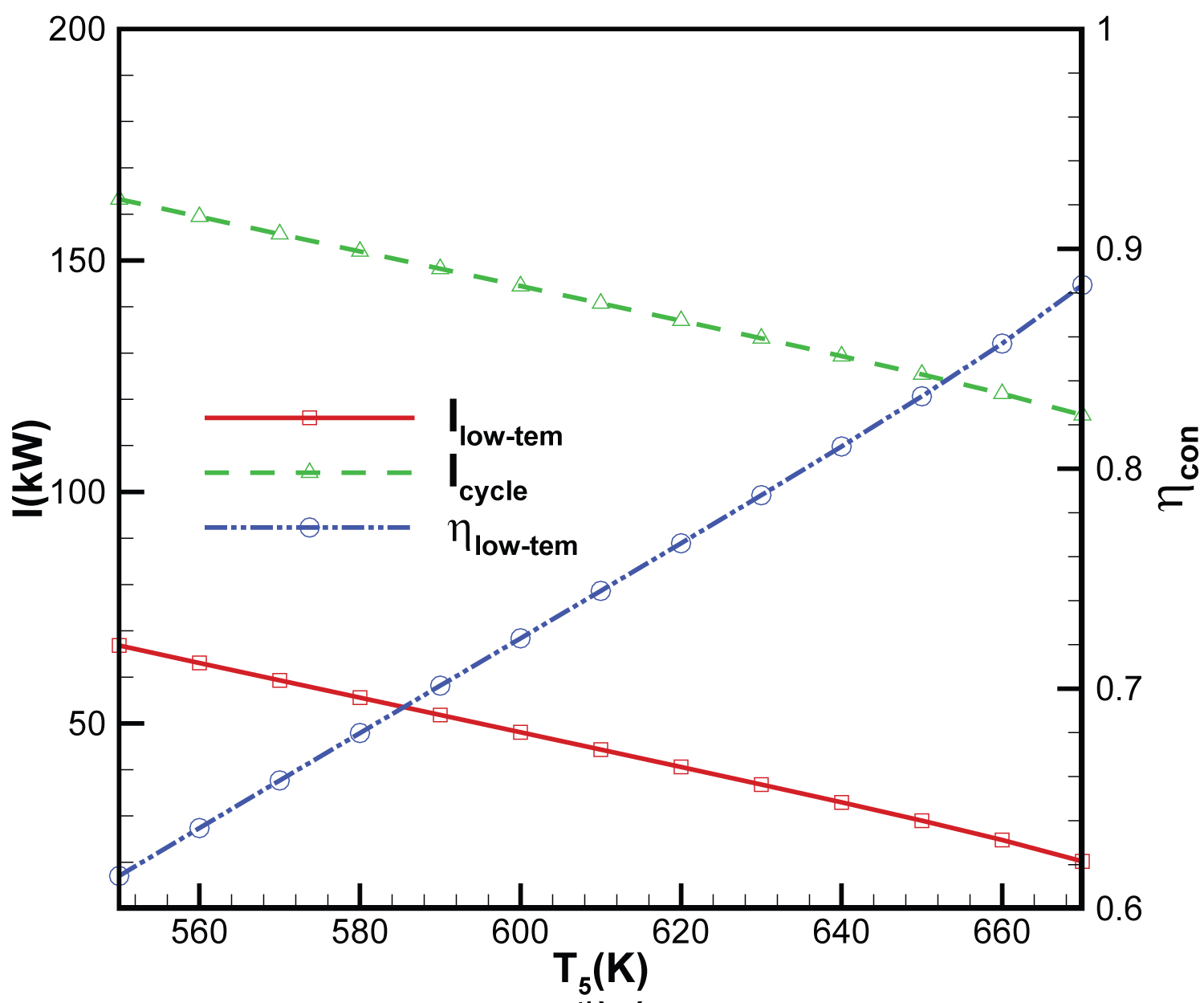
Figure 10: Irreversibility's and exergy...
Irreversibility's and exergy efficiency of the low-temp heat exchanger, irreversibility's of the cycle with fuel temperature of low-temp heat exchanger outlet.
Tables
Table 1: Parameters of CBC state points with helium.
Table 2: Representative exergy and energy performance data for the cycle.
References
- Chang J, Bao W, Yu D (2009) Hypersonic inlet control with pulse periodic energy addition. Proceedings of the Institution of Mechanical Engineers, Part G: Journal of Aerospace Engineering 223: 85-94.
- Mahapatra D, Jagadeesh G (2008) Shock tunnel studies on cowl/ramp shock interactions in a generic scramjet inlet. Proceedings of the Institution of Mechanical Engineers, Part G: Journal of Aerospace Engineering 222: 1183-1191.
- Kontis K (2008) Flow control effectiveness of jets, strakes, and flares at hypersonic speeds. Proceedings of the Institution of Mechanical Engineers, Part G: Journal of Aerospace Engineering 222: 585-603.
- Thompson T, Weeks D, Steven W, John A (2007) The DARPA/USAF falcon program update and the spaceX maiden launch, mishap investigation and return to flight. AIAA 2007-9912.
- Gascoin N, Gillard P, Dufour E, Toure Y (2007) Validation of transient cooling modeling for hypersonic application. Journal of Thermophysics and Heat Transfer 21: 86-94.
- Chang J, Bao W (2009) Effects of wall cooling on performance parameters of hypersonic inlets. Acta Astronautica 65: 467-476.
- Tsujikawa Y, Northam G (1996) Effects of hydrogen active cooling on scramjet engine performance. International Journal of Hydrogen Energy 21: 299-304.
- Qin J, Bao W, Zhou W, Yu D (2009) Performance cycle analysis of an open cooling cycle for scramjet. Proceedings of the Institution of Mechanical Engineers, Part G: Journal of Aerospace Engineering 223: 599-607.
- Bao W, Qin J, Zhou W, Yu D (2009) Parametric performance analysis of multiple re-cooled cycle for hydrogen fueled scramjet. International Journal of Hydrogen Energy 34: 7334-7341.
- Qin J, Bao W, Zhou W, Yu D (2008) Thermal management system performance analysis of hypersonic vehicle based on closed brayton cycle. 44th AIAA/ASME/SAE/ASEE Joint Propulsion Conference & Exhibit. AIAA 2008-5178.
- LeRoux W, Bello-Ochende T, Meyer J (2013) A review on the thermodynamic optimization and modelling of the solar thermal Brayton cycle. Renewable and Sustainable Energy Reviews 28: 677-690.
- Le Roux W, Bello-Ochende T, Meyer J (2011) Operating conditions of an open and direct solar thermal brayton cycle with optimised cavity receiver and recuperator. Energy 36: 6027-6036.
- Le Roux W, Bello-Ochende T, Meyer J (2012) Optimum performance of the small-scale open and direct solar thermal brayton cycle at various environmental conditions and constraints. Energy 46: 42-50.
- Feng H, Chen L, Sun F (2011) Exergoeconomic optimal performance of an irreversible closed brayton cycle combined cooling, heating and power plant. Applied Mathematical Modelling 35: 4661-4673.
- Serrano I, Linares J, Cantizano A, Moratilla B (2014) Modeling and sizing of the heat exchangers of a new supercritical CO2 Brayton power cycle for energy conversion for fusion reactors. Fusion Engineering and Design 89: 1905-1908.
- Serrano I, Linares J, Cantizano A, Moratilla B (2014) Enhanced arrangement for recuperators in supercritical CO2 Brayton power cycle for energy conversion in fusion reactors. Fusion Engineering and Design 89: 1909-1912.
- Qin J, Zhou W, Bao W, Yu D (2010) Thermodynamic analysis and parametric study of a closed brayton cycle thermal management system for scramjet. International Journal of Hydrogen Energy 35: 356-364.
- Naserian M, Farahat S, Sarhaddi F (2015) Finite time exergy analysis and multi-objective ecological optimization of a regenerative brayton cycle considering the impact of flow rate variations. Energy Conversion and Management 103: 790-800.
- Bao W, Qin J, Zhou W, Yu D (2010) Effect of cooling channel geometry on re-cooled cycle performance for hydrogen fueled scramjet. International Journal of Hydrogen Energy 35: 7002-7011.
- Ma X (2007) Study on coupled heat transfer in scramjet combustor and its cooling structure. Dissertation for the Master Degree. Harbin Institute of Technology, 7.
Author Details
Xinchun Li1*, Zhongwei Wang2 and Gang Ding1
1Equipment Management and Unmanned Aerial Vehicles Engineering College, Air Force Engineering University, China
2Science and Technology on Scramjet Laboratory, National University of Defense Technology, China
Corresponding author
Xinchun Li, Equipment Management and Unmanned Aerial Vehicles Engineering College, Air Force Engineering University, Xi`an 710051, China, Tel: +86-029-84788486; Fax: +86-029-84788486
Accepted: September 25, 2021 | Published Online: September 27, 2021
Citation: Li X, Wang Z, Ding G (2021) Energy and Exergy Analysis of a Closed Brayton Cycle for Power Generation from the Scramjet Cooling Heat. Int J Astronaut Aeronautical Eng 6:053.
Copyright: © 2021Li X, et al. This is an open-access article distributed under the terms of the Creative Commons Attribution License, which permits unrestricted use, distribution, and reproduction in any medium, provided the original author and source are credited.
Abstract
The scramjet for cooling and heat recovery has been an issue in hypersonic vehicle. A Closed Brayton Cycle (CBC) for power generation system from the heat of cooling scramjet is proposed. Energy, in conjunction with exergy, analysis of the scramjet cooling heat driven Closed Brayton Cycle (CBC) is performed. It is observed from the analysis that, the energy and exergy efficiencies of the system are 33.90% and 24.95%, respectively. Furthermore, the exergy destruction, the output power and the conversion efficiency of CBC following the high-temperature (high-temp) heat exchanger outlet working fluid temperature and the cycle pressure ratio have been analyzed. The cycle pressure ratio, the high-temp heat exchanger outlet working fluid temperature and the low-temperature (low-temp) heat exchanger outlet fuel temperature have large effects on both energy and exergy efficiencies.
Keywords
Energy, Exergy, Scramjet, Closed brayton cycle, Output power
Introduction
The key technology of hypersonic vehicle has been studied for many years, especially the issue for hypersonic airbreathing vehicles including Single-Stage-To-Orbit (SSTO) vehicles or Two-Stage-To-Orbit (TSTO) aerospace planes, reusable space transport vehicles and hypersonic cruise missiles [1-3]. One of the key technologies in hypersonic vehicle is the structure and thermal protection [4]. The cooling of scramjet is one of key issues because of large heat load in scramjet combustion chambers. The temperature of the ram air taken on board becomes higher with flight speeds increasing to the high supersonic and leading to barely cooling the structure. Therefore, the fuel is unique coolant for cooling the structure [5,6]. In this way, fuel cool the scramjet by flowing through the cooling passage and then it flows to the combustion chamber for burning [7].
So far, fuel coolant can only meet the cooling requirements for the components of scramjet such as combustion chamber. There is a new Re-cooling Cycle to indirectly increase fuel heat sink through repeatedly utilize fuel cooling capacity [8,9]. Based on the principle of work conversion of heat, part of thermal load in high temperature can be transferred to mechanical power and then the thermal load taken away by fuels was reduced [10]. In general, the electrical efficiency of Re-cooling Cycle is relatively low.
CBC has been used in many fields, especially the depletion of non-renewable energy becomes more serious and people's awareness about the environmental pollution. Many studies have been published on the performance and optimization of the solar thermal Brayton cycle showing the potential, merits and challenges of this technology [11-13]. A combined cooling, heating and power plant model composed of an irreversible CBC has been studied by using finite time thermodynamics [14]. Serrano and Linares [15,16] have studied the optimization of heat recovery from the reactor and its conversion into electrical power. A parametric study of an irreversible CBC thermal management system for scramjet has been performed [17]. Energy and exergy analysis is useful for thermodynamic processes. Farahat [18] has presented the optimal performance of a regenerative Brayton cycle using finite-time thermodynamic concept and finite-size components. The property of CBC for power generation system on scramjet is relative scarce. Otherwise, the exergy destruction, the power output and the conversion efficiency of CBC is fewly studied.
In this paper, the potential work between the high temperature of scramjet wall and the lower temperature of fuel coolant is calculated. A CBC suitable for power generation system is presented. An exergy analysis in conjunction with energy analysis is performed on CBC and the locations and magnitudes of exergy destruction are identified and quantified. And then the exergy destruction, the output power and the conversion efficiency of CBC are evaluated. At last the effects of the turbine inlet temperature and the cycle pressure ratio on exergy and energy efficiencies are analyzed. Meanwhile, the effect of the temperature of low-temp heat exchanger outlet on its exergy efficiency is also analyzed.
Power Generation System Description
Figure 1 presents a layout of a power generation system with the heat source of scramjet wall and a direct CBC.
Typical ramp heat fluxes of scramjet vary from 2 to 20 MW/m2 [19]. The cooling passage of the scramjet wall is regarded as high-temp heat exchanger and the working fluid of CBC is heated in there. And then, the high temperature and pressure working fluid flows in turbine and gives output power. Working fluid from the turbine outlet is entered into low-temp heat exchanger and cooled by the fuel coolant. At last, working fluid enters the compressor inlet and one cycle is completed.
The turbine can make the compressor and the pump working normally. Meanwhile, an assumed output power can be taken as the input of the whole hypersonic vehicle. Chemistry performance of working fluid is important for CBC, such as inert gases. Helium is selected to regard as the working fluid for CBC.
The Net Exergy Transfer by Heat
It supposed that the temperature distribution of hot and cold sources is show in Figure 2. The mechanics of scramjet is supposed as axial symmetry. The scramjet isolator inlet is regarded as the zero point of coordinate and the flowing direction is along x-axis. The cross-section perimeter of scramjet is . The heat source temperature distribution is , heat fluxes distribution is and cold source temperature distribution is .
The theoretical carnot cycle is supposed between hot and cold sources. In the infinitesimal element with a length dx of the scramjet wall, the heat flow from scramjet wall can be written as
According to Fourier's heat conduction law, the heat fluxes is expressed as
In the infinitesimal element with a length dx, the largest available work is written as
The available work can be calculated from location a1 to location a2. It is written as
Energy and Exergy Analysis
The CBC consists of several steady state control volumes. General expressions of mass, energy, and exergy balances of any steady state control volume, by neglecting the potential and kinetic energy changes, can be given respectively as
Where the subscripts "in" and "out" represent the inlet and exit states respectively, Q and W are the net heat and work inputs respectively, m is the mass flow rate, E is the exergy rate which is equal to me and the specific the flow exergy is given by and I is the irreversibility's rate. is the net exergy (Eq.(4)).
Exergy balance for the high-temp and the low-temp heat exchanger are defined as
Where and are high-temp and low-temp heat exchanger irreversibility's, respectively.
Exergy efficiency of the high-temp and low-temp heat exchanger can be defined as the exergy recovered by cold stream divided by exergy supply from hot gas. Applying this definition to the high-temp and low-temp heat exchanger, we obtain
Exergy efficiency of the turbine shows the actual turbine output is obtained from the exergy. In fact, the turbine actual work can be calculated by subtracting turbine irreversibility's from reversible work . Then, Energy, exergy balances and exergy efficiency of the turbine can be expressed respectively as
Energy conservation, exergy balance and exergy efficiency of the compressor are defined as ( is irreversibility's of the compressor.)
Where, .
The overall exergy efficiency of the entire cycle can be written as
The total exergy destruction in the cycle is the sum of the all-exergy destructions in the subcomponents of the cycle. However, total exergy loss in the cycle is sum of total exergy destruction and exergy transferred to low-temp heat exchanger fuel coolant. It can be defined as the difference between the exergy recovered from the scramjet wall and the net power output from the cycle.
Results and Discussions
The net exergy transfer by heat
The Mach number of air stream to scramjet isolator inlet is about 1.5 ~ 3.5 when the Mach number of air stream is about 6. The total pressure and total temperature of airstream are 1.68 MPa, 1200 K, respectively.
The temperature distribution of scramjet wall is different. The scramjet isolator inlet wall temperature is supposed about 700 K and the scramjet isolator outlet wall temperature is increasing to 1200 K. The assumed temperature distribution on the scramjet wall is about as [20].
On the assumption of the scramjet wall temperature distribution, we can estimate the heat fluxes which is about 0.4 MW/m2.
It is supposed that the initial temperature for hydrocarbon fuel coolant is 300 K which can be treated as cold source temperature. The average cross section perimeter of scramjet is taken 0.65 m. The total heat flow can be calculated as
The net exergy is written as
The total heat is calculated about 553.8 kW, and the exergy is about 407.7 kW.
Energy and exergy analysis of CBC
It is supposed that the temperature and pressure of compressor inlet working fluid are 350 K and 0.1 MPa, respectively. The ratio of pressure is selected as 3.3, the T2 is 600 K. So the temperature and pressure of turbine inlet working fluid are 1100 K and 0.33 MPa, respectively. The thermodynamics parameters of state points 1, 2, 3, 4 are given in Table 1.
The rate of working fluid is calculated about 0.213 kg/s from Table 1. It is supposed that the temperature of the low-temp heat exchanger inlet and outlet fuel are 300 K and 600 K, respectively, the pressure of fuel is about 2.5 MPa, the average specific heat of fuel is (dodecane is regarded as fuel). The rate of fuel flow is calculated 0.460 kg/s.
Representative exergy and energy performance data for the cycle are listed in Table 2. The CBC extracts 553.8 kW heat from the scramjet wall and produces 138.2 kW output power. The energy efficiency of CBC is 24.95%. 415.6 kW which is 75.05% of the heat input to the cycle, is rejected from the low-temp heat exchanger. The highest exergy destruction occurs during heat exchange process in the high-temp heat exchanger. The exergy destruction is 55.0 kW, which is the 13.5% of exergy. Although the irreversibility's occur in the low-temp heat exchanger lower than that of the high-temp heat exchanger, due to the exergy transferred to the cooling fuel, the total exergy loss at the low-temp heat exchanger is higher than that of the high-temp heat exchanger. Figure 3 illustrates the exergy losses, which is expressed as the percentage of exergy.
Figure 4 shows the changes in the high-temp heat exchanger, the low-temp heat exchanger, the turbine and the compressor working fluid irreversibility's with the temperature of high-temp heat exchanger outlet. Irreversibility's of the high-temp heat exchanger, the turbine and the compressor decrease while those of the low-temp heat exchanger increase. The total irreversibility's of the high-temp heat exchanger, the turbine and the compressor for 1050 K and 1150 K are 105.1 kW and 86.9 kW, respectively, while irreversibility's of the low-temp heat exchanger for 1050 K and 1150 K are 44.0kW and 52.1 kW, respectively. It is supposed that the isentropic efficiency of compressor is 0.85 and the isentropic efficiency of turbine is 0.9. Thus, the temperature of turbine outlet increases. Therefore, the exergy efficiency of the high-temp heat exchanger increases while the exergy efficiency of the low-temp heat exchanger decreases. Figure 5 shows the variation of exergy efficiencies of the Components. Figure 6 shows the variation of net power, exergy and energy efficiency of the cycle, irreversibility's of cycle. The overall net power, energy and exergy efficiency of the cycle increase with the high-temp heat exchanger outlet working fluid temperature, since the total irreversibility's of the cycle decreases. When heat input to the cycle is constant, the mass flow rate of the Helium will decrease by increasing the temperature of the high-temp heat exchanger outlet. The compressor work decreases due to lower mass flow rate. Working fluid enthalpy drop between the turbine inlet and outlet increases, but the decreased mass flow rate prevents this salutary effect and causes the work production to be decreased. However, the work production decrease is slower than that of the compressor. Therefore, the net power, the exergy and the energy efficiency of the cycle increase.
Figure 7 shows the changes in the high-temp heat exchanger, the low-temp heat exchanger, the turbine and the compressor irreversibility's with pressure ratio of the cycle. Irreversibility's of the high-temp and the low-temp heat exchangers decrease while those of the turbine and the compressor increase. The total irreversibility's of the high-temp heat exchanger and the low-temp heat exchanger for pressure ratios 2 and 4 are 166.1 kW and 84.2 kW, respectively, while the total irreversibility's of the turbine and the compressor are 19.7 kW and 53.7 kW, respectively. The total irreversibility's of the cycle for pressure ratios are 285.8 kW and 137.9 kW, respectively. The exergy efficiencies of the high-temp and the low-temp heat exchanger increase. Figure 8 shows the variations of exergy efficiencies of the Components. Figure 9 shows the variation of the net power, the exergy and the energy efficiency of the cycle, the irreversibility's of cycle. The overall net power, the energy and the exergy efficiencies of the cycle increases with the increase of pressure ratio, while the total irreversibility's of the cycle decrease.
Figure 10 shows the changes in the irreversibility's and the exergy efficiency of the low-temp heat exchanger, irreversibility's of the cycle with fuel temperature. Irreversibility's of the low-temp heat exchanger and the cycle decrease with the increase of the low-temp heat exchanger outlet fuel temperature. Therefore, the exergy efficiency of the low-temp heat exchanger increases.
Conclusion
A physical model of the CBC for power generation system is constructed for recovering the scramjet cooling heat, and the energy and exergy of the system are discussed. According to such analysis, the following conclusions are drawn from the system investigation in this paper:
1) With the assumption of the heat source temperature distribution, cold source temperature distribution, heat fluxes distribution and the scramjet average cross section perimeter, the total heat from cooling scramjet is calculated about 553.8 kW, and the exergy is about 407.7 kW.
2) Based on the given temperature and pressure of compressor inlet working fluid, the assumption of the ratio of pressure, the T2 and T3, the energy and the exergy efficiencies of the system are 33.90%, 24.95%, respectively, the output power is 138.2 kW.
3) The high-temp heat exchanger outlet fluid temperature and the cycle pressure ratio have large effects on the exergy destruction, the power output and the energy and the exergy efficiency of the CBC system. The low-temp heat exchanger outlet fuel temperature also has effects on the system exergy efficiency. The proposed results can be used to help ongoing efforts to improve the performance of the heat for cooling scramjet driven CBC and give some output power for hypersonic vehicle.