
International Journal of Astronautics and Aeronautical Engineering
(ISSN: 2631-5009)
Volume 6, Issue 2
Original Article
DOI: 10.35840/2631-5009/7555

Article Formats
Performance Parameter Analysis of Thermoelectric Generators for Power Generation System from the Scramjet Cooling Heat
Table of Content
Figures
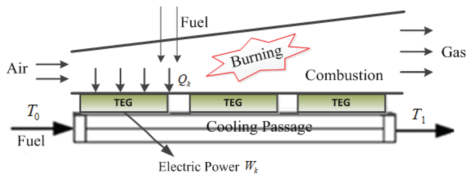
Figure 1: Conceptual scheme of power generation...
Conceptual scheme of power generation system integrated TEGs and cooling passage.
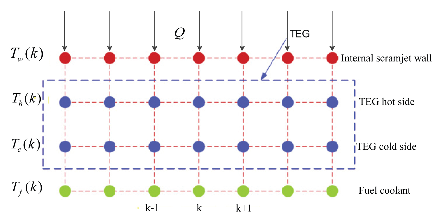
Figure 2: Calculation method for integrated....
Calculation method for integrated TEG and cooling passage.
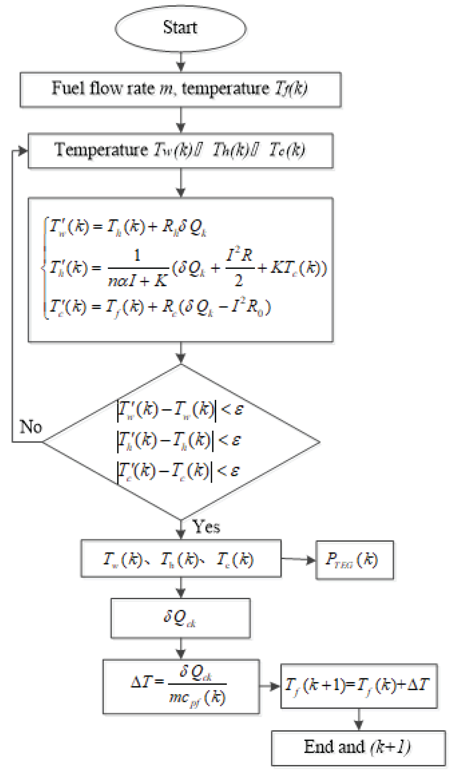
Figure 3: The flow chart of the heat transfer....
The flow chart of the heat transfer method for integrated TEG and cooling passage.

Figure 4: Variation of the temperature....
Variation of the temperature along the scramjet length with fuel flow rate 0.04 kg/s.
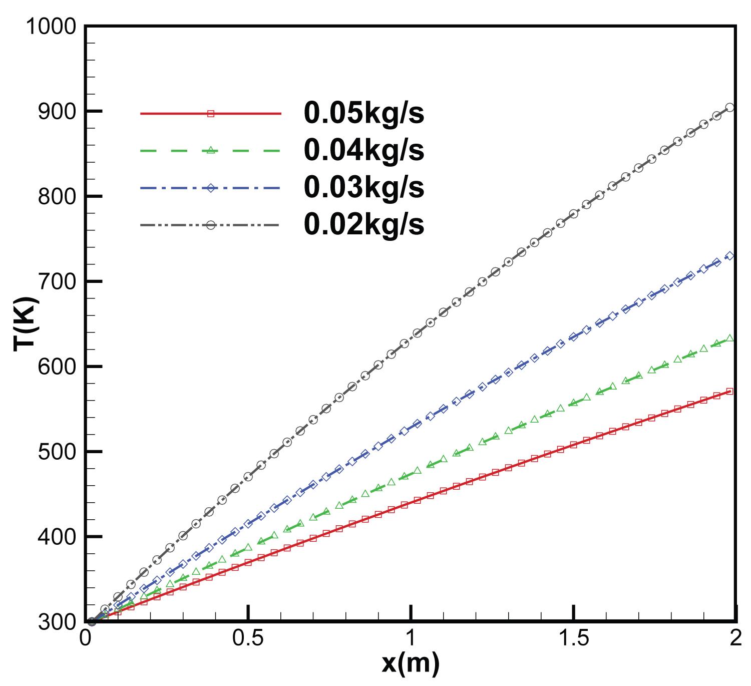
Figure 5: Variation of the fuel coolant....
Variation of the fuel coolant temperature with different fuel flow rates.
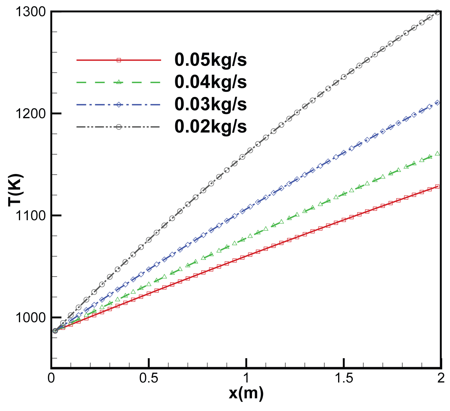
Figure 6: Variation of the scramjet internal....
Variation of the scramjet internal wall temperature with different fuel flow rates.
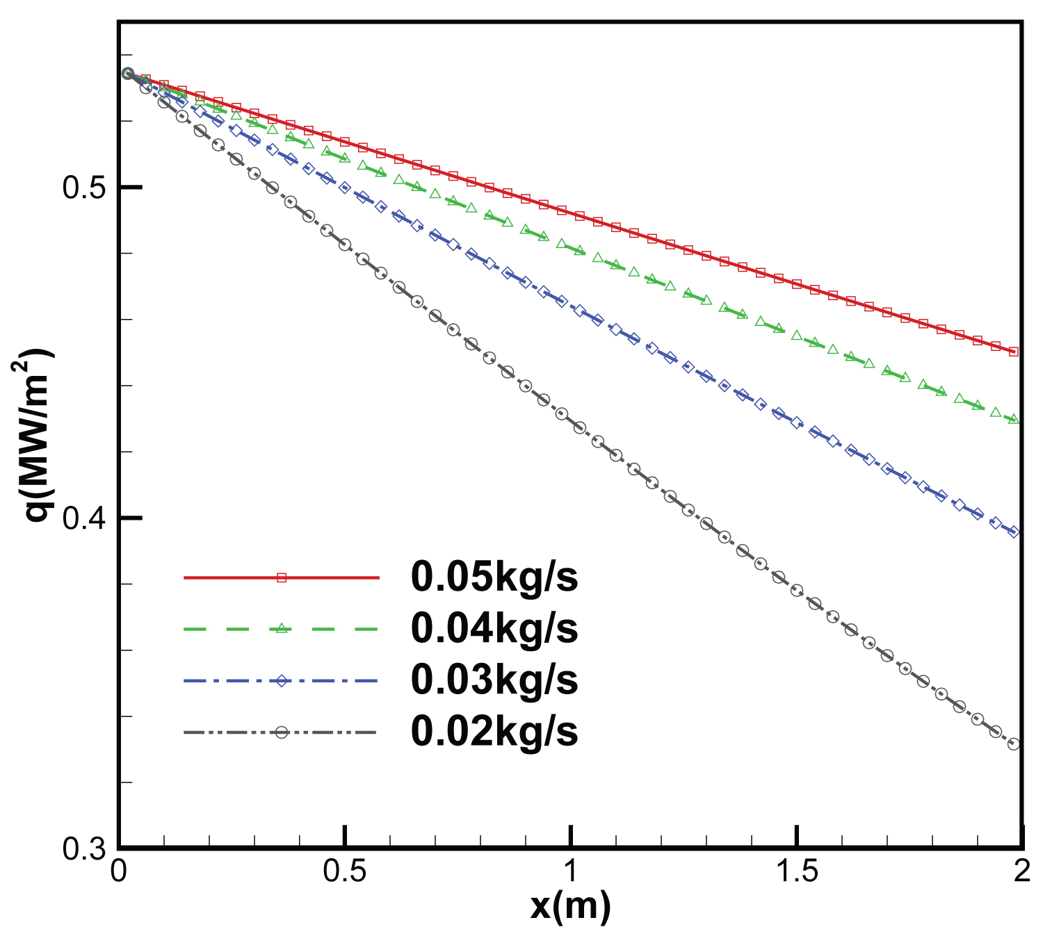
Figure 7: Variation of the scramjet internal...
Variation of the scramjet internal wall heat flux with different fuel flow rates.
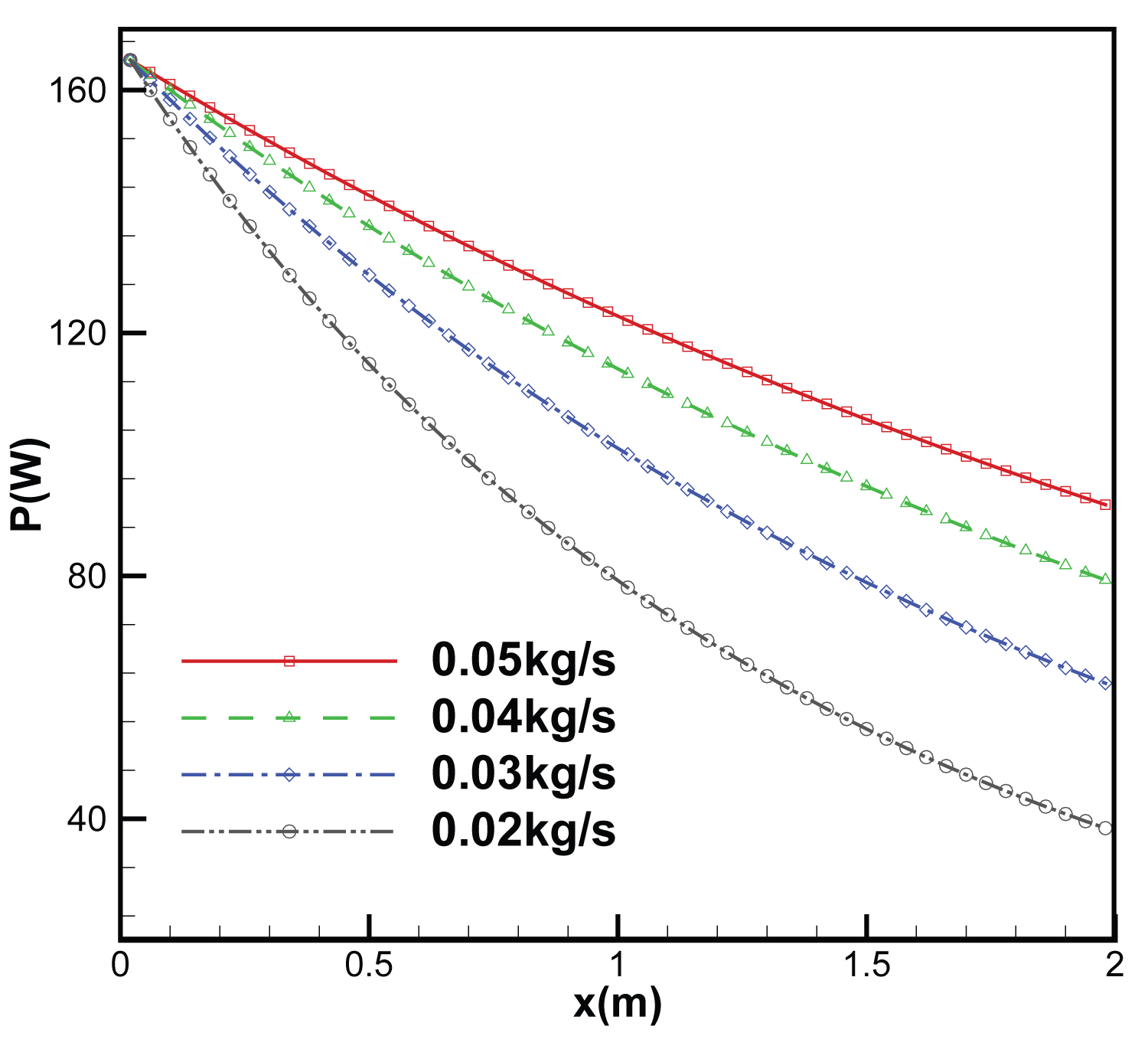
Figure 8: Variation of the output power of...
Variation of the output power of TEG with different fuel flow rates.
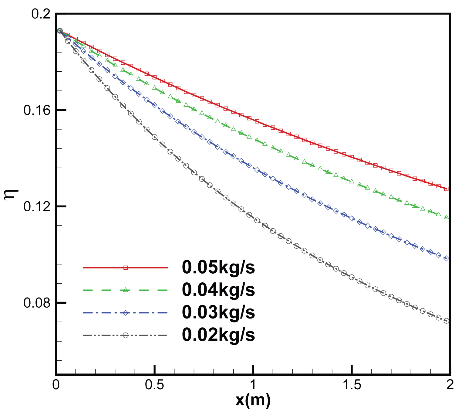
Figure 9: Variation of the conversion efficiency...
Variation of the conversion efficiency of TEG with different fuel flow rates.
Tables
Table 1: Main parameters of the TEG.
Table 2: Main structures properties for computation.
Table 3: The calculation of heat flow, total power output, conversion efficiency and the fuel flow saving ratio with different fuel flow rates.
References
- Chang J, Bao W, Yu DR, Fan Y, Shen Y, et al. (2009) Hypersonic inlet control with pulse periodic energy addition. J Aerospace Eng 223: 85-94.
- Mahapatra D, Jagadeesh G (2008) Shock tunnel studies on cowl/ramp shock interactions in a generic scramjet inlet. J Aerospace Eng 222: 1183-1191.
- Kontis K (2008) Flow control effectiveness of jets, strakes, and flares at hypersonic speeds. J Aerospace Eng 222: 585-603.
- Thompson T, Weeks D (2007) The DARPA/USAF falcon program update and the spaceX maiden launch. AIAA 2007-9912.
- Bao W, Qin J, Yu DR (2006) Integrated thermal management method of energy based on Closed Brayton Cycle for scramjet. In: Proceedings of the 42nd AIAA/ASME/SAE/ASEE Joint Propulsion Conference, California.
- Carpenter C, Verma S, Kapat JS (2013) Numerical study of enhancement of regenerative cooling using ribs. In: Proceedings of the 49th AIAA/ASME/SAE/ASEE Joint Propulsion Conference, San Jose, CA.
- Gascoin N, Gillard P, Dufour E, Toure Y (2007) Validation of transient cooling modeling for hypersonic application. J Thermophys Heat Tr 21: 86-94.
- Chang J, Bao W (2009) Effects of wall cooling on performance parameters of hypersonic inlets. Acta Astronaut 65: 467-476.
- Tsujikawa Y, Northam G (1996) Effects of hydrogen active cooling on scramjet engine performance. INT J Hydrogen Energ 21: 299-304.
- Qin J, Bao W, Zhou WX, Yu DR (2009) Performance cycle analysis of an open cooling cycle for scramjet. J Aerospace Eng 223: 599-607.
- Bao W, Qin J, Zhou WX, Yu DR (2009) Parametric performance analysis of multiple re-cooled cycle for hydrogen fueled scramjet. INT J Hydrogen Energ 34: 7334-7341.
- Bao W, Qin J, Zhou WX, Yu DR, Zhang D (2011) Power generation and heat sink improvement characteristics of recooling cycle for thermal cracked hydrocarbon fueled scramjet. Sci China Technol Sci 54: 955-963.
- Bao W, Qin J, Zhou WX, Zhang D (2012) Performance analysis on fuel turbo-pump and motor system of scramjet engine. In: Proceedings of the 10th International Energy Conversion Engineering Conference, Georgia.
- Tang ZB, Deng YD, Su CQ (2015) A research on thermoelectric generator's electrical performance under temperature mismatch conditions for automotive waste heat recovery system. Case Studies Thermal Eng 5: 143-150.
- Ahiska R, Dislitas S (2011) Computer controlled test system for measuring the parameters of the real thermoelectric module. Energ Convers Manage 52: 27-36.
- Yang Q, Chang J, Bao W (2014) Thermodynamic analysis on specific thrust of the hydrocarbon fueled scramjet. Energy. 76: 552-558.
- Meng F, Chen LG, Sun F (2011) A numerical model and comparative investigation of a thermoelectric generator with multi-irreversibilities. Energy 36: 3513-3522.
- Yilbas B, Sahin A (2010) Thermoelectric device and optimum external load parameter and slenderness ratio. Energy 35: 5380-5384.
- Sahin A, Yilbas B, Shuja S, Momin O (2011) Investigation into topping cycle: Thermal efficiency with and without presence of thermoelectric generator. Energy 36: 4048-4054.
- Q Du, H Diao, Z Niu, G Zhang, G Shu, et al. (2015) Effect of cooling design on the characteristics and performance of thermoelectric generator used for internal combustion engine. Energ Convers Manage 101: 9-18.
- In B, Kim H, Son J, Lee K (2015) The study of a thermoelectric generator with various thermal conditions of exhaust gas from a diesel engine. INT J Heat Mass Tran 86: 667-680.
- Shu GQ, Zhao J, Tian H, Liang XY, Wei HQ (2012) Parametric and exergetic analysis of waste heat recovery system based on thermoelectric generator and organic rankine cycle utilizing R123. Energy 45: 806-816.
- Jon M, Frederick D, Alp S (2015) Si/Ge-WSi2 composites: Processing and thermoelectric properties. Acta Mater 98: 263-274.
Author Details
Xinchun Li1*, Zhongwei Wang2 and Liang Zhang1
1Equipment Management and Unmanned Aerial Vehicles Engineering College, Air Force Engineering University, China
2Science and Technology on Scramjet Laboratory, National University of Defense Technology, China
Corresponding author
Xinchun Li, Equipment Management and Unmanned Aerial Vehicles Engineering College, Air Force Engineering University, Baqiao District, Changle East Road, Xi'an 710051, China, Tel: +86-029-84788486; Fax: +86-029-84788486
Accepted: October 11, 2021 | Published Online: October 13, 2021
Citation: Li X, Wang Z, Zhang L (2021) Performance Parameter Analysis of Thermoelectric Generators for Power Generation System from the Scramjet Cooling Heat. Int J Astronaut Aeronautical Eng 6:055.
Copyright: © 2021 Li X, et al. This is an open-access article distributed under the terms of the Creative Commons Attribution License, which permits unrestricted use, distribution, and reproduction in any medium, provided the original author and source are credited.
Abstract
Thermoelectric generator (TEG) for power generation system is proposed for energy recovery. The heat from cooling scramjet would be converted to electric energy. A parametric study of TEGs power generation system for heat recovery has been performed. The output power, the efficiency and the fuel flow saving ratio of the system have been analyzed and the proposed heat transfer analysis method of the system is depicted. Numerical results indicate that the total output power, the efficiency and the fuel flow saving ratio increase with the increase of fuel coolant flow rate. According to the analysis, the total output power is 70.1 kW, the efficiency is 14.5% and the fuel flow saving ratio is 0.170 when the fuel coolant flow rate is 0.48 kg/s with 12 rows TEGs. Most important, valuable amount of output power can be drawn by employing TEGs power generation system for hypersonic vehicles powered by scramjet.
Keywords
Energy recovery, Scramjet, TEG, Output power, Fuel coolant
Introduction
The issue of hypersonic airbreathing vehicle [1-3] has been studied for many years. With the high flight speed, the structure and thermal protection for hypersonic vehicle is of great importance [4]. The aerothermal environment surrounding the scramjet wall is so severe that it suffers a great amount of heat flux about 7 ~ 8 MW/m2 in NASA-Langley airframe propulsion integrated ramjet engine [5]. Therefore, cooling scramjet is one of the critical technologies for airbreathing hypersonic vehicles equipped with scramjet. The regenerative cooling cycle is the most commonly used technique for scramjet cooling [6,7]. Within the cycle, the fuel coolant flows through the cooling passage for cooling the structure [8,9]. But fuel coolant can only cool the scramjet components such as combustion chamber, and the high temperature and heat flux of the scramjet wall have not been effectively utilized in a conventional thermal conversion way to produce electricity. There once existed a new Re-cooling Cycle which contained a turbine to transfer enthalpy from fuel to mechanical work and electric power [10,11]. However, only part of fuel heat is converted to mechanical power [12,13]. In general, the electrical efficiency of Re-cooling Cycle is relatively low.
Energy recovery has been a hot issue in all kinds of engines in recent years. In the case of waste heat recovery the thermoelectric generator (TEG) is a device for directly converting thermal energy into electrical energy [14]. The TEGs have many advantages such as no moving mechanical parts, long-lived, quiet, environmentally friendly and requiring little maintenance [15]. For flight vehicles especially hypersonic aircrafts powered by scramjet, extremely high temperature and heat flux are encountered within the combustor [16]. The heat of cooling scramjet would make energy recovery more necessary. Meanwhile, the auxiliary systems such as fuel feeding, environment control on aircraft need a large amount of power.
TEG can recover engine waste heat in a straightforward manner [17-19]. Du, et al. [20] developed a thermoelectric generator (TEG) model coupled with exhaust and cooling channels for an exhaust-based TEG (ETEG) system, and then investigated the influence of the cooling type, coolant flow rate, length, number and location of bafflers. Ref. [21] provided useful information on optimization of the TEG system, including optimization of the system layout, and configuration of TEG and predicted the heat transfer characteristics of thermoelectric modules by theoretical analysis. There hasn't been an abundance of literature and researches about using TEG for power generation from the heat of cooling scramjet.
In this paper, an integrated TEG and regenerative cooling for power generation system is proposed firstly, and there is part of the heat from cooling scramjet and it would be converted to electric energy. The performance parameter analysis of TEGs is presented such as the efficiency, power output and the fuel flow saving ratio. And then the temperature and heat flux distribution of the cooling passage with TEG are calculated by the method of heat equilibrium according to heat transfer and thermal conversion. At last the output power, the efficiency and the fuel flow saving ratio are calculated with different fuel coolant flow rates.
Tegs Power Generation System
Configuration of the integrated TEG and cooling passage is illustrated in Figure 1. Typical ramp heat flux of scramjet wall varies from 2 to 20 MW/m2 [22]. The integrated energy system consists of TEGs and the cooling passage. The input heat from the scramjet transfers to the TEG hot side and the electric power is generated and supplied to the load. The dissipated heat from the TEG cold side is absorbed by the fuel coolant. The scramjet wall and the fuel coolant are regarded as hot and cold sources respectively for TEGs and the electric power is generated when the heat flows to the coolant across TEG. The fuel from cooling passage outlet is injected into the combustor. Both aims of scramjet cooling and power generation can be achieved.
Parameter Analysis
There is a new performance parameter to compare the performance of TEGs system with that of regenerative cooling. Under the same external heating condition, assumptions are made, namely (1) Constant fuel specific heat, (2) Constant TEG's thermoelectric performance, (3) No pressure loss from cooling passage and heat exchanger, (4) No heat transfer loss.
For regenerative cooling, the cooling capacity of fuel absorbs heat when the fuel coolant in cooling passage inlet and outlet temperatures are and , respectively, and the mass flow rate of fuel is . As for the TEGs system, the numbers of TEGs are n, and one of the TEGs heat flow is supposed , output power with the same fuel flow rate of . Therefore, the total of heat flow is and the whole output power .
For regenerative cooling, the cooling capacity of fuel can be expressed as
Where is specific heat of the fuel coolant.
For TEGs system, when the fuel flow rate is , the cooling capacity of the system can be written as
The efficiency of TEG is based on the hot and cold side temperatures. One of the TEGs efficiency is expressed as
Where Thk and Tck are the hot and cold temperatures, respectively, is the Carnot efficiency expressed as , m is the ratio of the load resistance and inner resistance, Z is the thermoelectric materials Figure of Merit expressed as , are the Seebeck coefficient, thermal conductivity and electrical resistivity, respectively.
The maximum efficiency is expressed as
Where
One of the TEGs heat flow is calculated as
Where and are the temperature of the scramjet wall and TEG's hot side, respectively, is the thermal resistance.
The maximum output power of TEG is expressed as
The total output power of TEGs system is calculated as
The efficiency of TEGs system is expressed as
In order to evaluate the performance of cooling scramjet, the fuel flow saving ratio is defined as
Heat Transfer and Thermal Conversion Analysis
The mechanics of scramjet is supposed to be axisymmetric. The scramjet isolator inlet is regarded as the zero point of coordinate and the flowing direction is along x-axis. The cross-section perimeter of scramjet is taken as . The scramjet internal wall temperature distribution is , and the heat flux distribution is . In the infinitesimal element with a length dx of the scramjet wall, the heat flow from scramjet wall can be written as
According to the heat flux performance of scramjet wall, the heat flow of scramjet wall is expressed as
Where and represent the convective flux and radiative heat flux, respectively, is the convective heat transfer coefficient, , and are the effective emissivity, the gas emissivity and the scramjet wall emissivity, respectively, and are the gas recovery temperature and static temperature, respectively, is the black body radiation constant, .
The temperature on the different sites of TEGs and cooling passage is strongly changed when the fuel coolant flow rate is different. The Mach number of airstream to scramjet isolator inlet is about 1.5 ~ 3.5 when the Mach number of airstream is about 6. The total temperature of scramjet combustion is about 2400 K. The length of the scramjet is taken 2000 mm and the average cross section perimeter of scramjet is taken 500 mm. There must be a relationship of the heat flux equilibrium from the scramjet wall to fuel coolant, as expressed in Eqs. (12),
Where is the heat flux and is equal to , and are the TEG's electric current and internal electrical resistance, respectively, is the TEG's power load, and are the temperature of the scramjet wall, TEG's hot side, TEG's cold side and the fuel coolant, respectively, is the numbers of thermoelectric units, and are the thermal resistances, is the thermal conductance of the TEG, which is expressed as
, and are expressed as
Where and represent the thickness of scramjet inner wall to TEG's hot side and TEG's cold side to the cooling passage, respectively.
Results and Discussion
The heat transfer analysis of the system with integrated TEG and cooling passage is based on the heat equilibrium equations and the output power of TEG is in the maximum way. The parameters of TEG [23] are presented in Table 1 and the main properties of other structures are shown in Table 2. The structure material is the high-temperature alloy such as Ni-based alloys and the coolant is hydrocarbon fuel. The computational model to analyze the integrated TEG and cooling passage is developed using discretization method, as shown in Figure 2.
The process of heat transfer analysis is illustrated in Figure 3, which depicts the flow chart of the proposed method. The fuel coolant flow rate is m and it's supposed that the original temperatures are and , respectively for one of the TEGs temperature at different sites. The real temperatures would be obtained according to the heat equilibrium equations. The output power of TEG and the dissipated heat absorbed by the fuel are also calculated. And then the heat transfer for next TEG would be analyzed.
Figure 4 shows the distribution of the temperature along the scramjet length with one row TEGs when the fuel flow rate is 0.04 kg/s. The fuel coolant temperature increases along the scramjet length. Meanwhile, the temperatures of the scramjet internal wall, the TEG hot and cold side also increase, but they increase slower than the fuel coolant temperature because the heat flux decreases with increasing the scramjet internal wall temperature. When the fuel flow rate is 0.04 kg/s, the fuel coolant temperature of cooling passage outlet is 632.5 K and the highest temperature of the scramjet internal wall is 1160.4 K lower than 1200 K which is currently promised biggest temperature for materials. On this condition, the TEG hot and cold side temperatures are 1117.4 K and 832.6 K, respectively.
As shown in Figure 5, the distribution of the fuel coolant temperature presents parabola along the scramjet length with one row TEGs and different fuel flow rate. The fuel coolant temperature increases with the decrease of fuel flow rate. When the fuel flow rate is 0.05 kg/s, 0.04 kg/s, 0.03 kg/s and 0.02 kg/s, respectively, the cooling passage outlet fuel temperature is 570.7 K, 632.5 K, 730.0 K and 904.3 K, respectively. Meanwhile, the temperature of the scramjet internal wall also increases. Figure 6 shows the distribution of the scramjet internal wall temperature along the scramjet length with different fuel flow rate. The highest scramjet internal wall temperatures are 1128.3 K, 1160.4 K, 1210.6 K and 1299.1 K, respectively, when the fuel flow rates are 0.05 kg/s, 0.04 kg/s, 0.03 kg/s and 0.02 kg/s, respectively. Figure 7 shows the distribution of the heat flux along the scramjet length. The heat flux decreases when the scramjet internal wall temperature increases.
Figure 8 shows the variation of the output power of TEGs along the scramjet length with different fuel flow rate. The power output increases with the increase of fuel flow rate. When the fuel coolant flow rate increases, the TEG's cold side temperature would decrease by an extent larger than the TEG's hot side temperature, and the temperature difference between TEG's hot and cold sides increases. Therefore, the output power of TEGs is increased. On the contrary, with the increase of fuel coolant temperature, the temperature difference between TEG's hot and cold sides decreases, resulting that the output power of TEGs decreases. Likewise, the efficiency of TEG along the scramjet length with different fuel flow rate decreases in Figure 9. The maximum efficiency of TEG appears in the cooling passage inlet and the minimum efficiency locates in the cooling passage outlet. The efficiency of TEG increases with the increase of fuel flow rate.
With the length of the scramjet as 2000 mm and the average cross section perimeter of scramjet as 500 mm, the number of the TEGs distributed is about 50 and the number of the TEG's rows along the scramjet cross section perimeter is 12. Thus, the total fuel coolant flow rates to cooling passage are 0.60 kg/s, 0.48 kg/s, 0.36 kg/s and 0.24 kg/s, respectively. Therefore, the total heat flux are calculated, and the total output power, efficiency as well as the fuel flow saving ratio can also be calculated in Table 3.
Conclusions
A physical model of the TEG for power generation system is constructed for recovering the scramjet cooling heat, and the performance parameters of the system are discussed. According to such analysis, the heat transfer analysis method of the system is depicted and the computational model to analyze the system is developed using discretization method. The following conclusions are drawn from the system parameters performance investigation in this paper:
The fuel coolant temperature increases along the scramjet length with one row TEGs when the fuel flow rate is 0.04 kg/s. The temperatures of the scramjet internal wall, the TEG hot and cold side also increase, but they increase slower than the fuel coolant temperature.
According to the analysis, the total output power is 70.1 kW, the efficiency is 14.5% and the fuel flow saving ratio is 0.170 when the fuel coolant flow rate is 0.48 kg/s with 12 rows TEGs. By analyzing the influence of fuel coolant flow rates, the total output power, the efficiency and the fuel flow saving ratio increase with the increase of fuel coolant flow rate. There is some output power for hypersonic vehicle obtained from the TEGs power generation system, which indicates the potential value lying in the application of this system.
The performance of TEG and the heat transfer performance of the cooling duct will be study. It is meaningful and helpful to improve the performance of the heat for cooling scramjet. It is also helpful for hypersonic vehicles to obtain some power from the power generation system.