
International Journal of Electronics and Device Physics
(ISSN: 2631-5041)
Volume 4, Issue 1
Research Article
DOI: 10.35840/2631-5041/1708

Article Formats
Three-Dimensional Proximity Sensing with Simple Circuit Made of General-Purpose Electronic Components
Table of Content
Figures
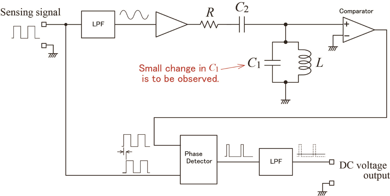
Figure 1: (Color online) Schematic of the principle....
(Color online) Schematic of the principle of detecting small capacitance changes.
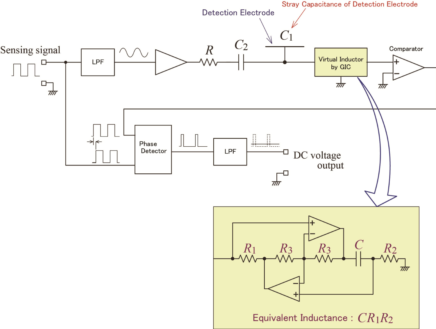
Figure 2: (Color online) Circuit for proximity sensing.....
(Color online) Circuit for proximity sensing using GIC as a virtual inductor.
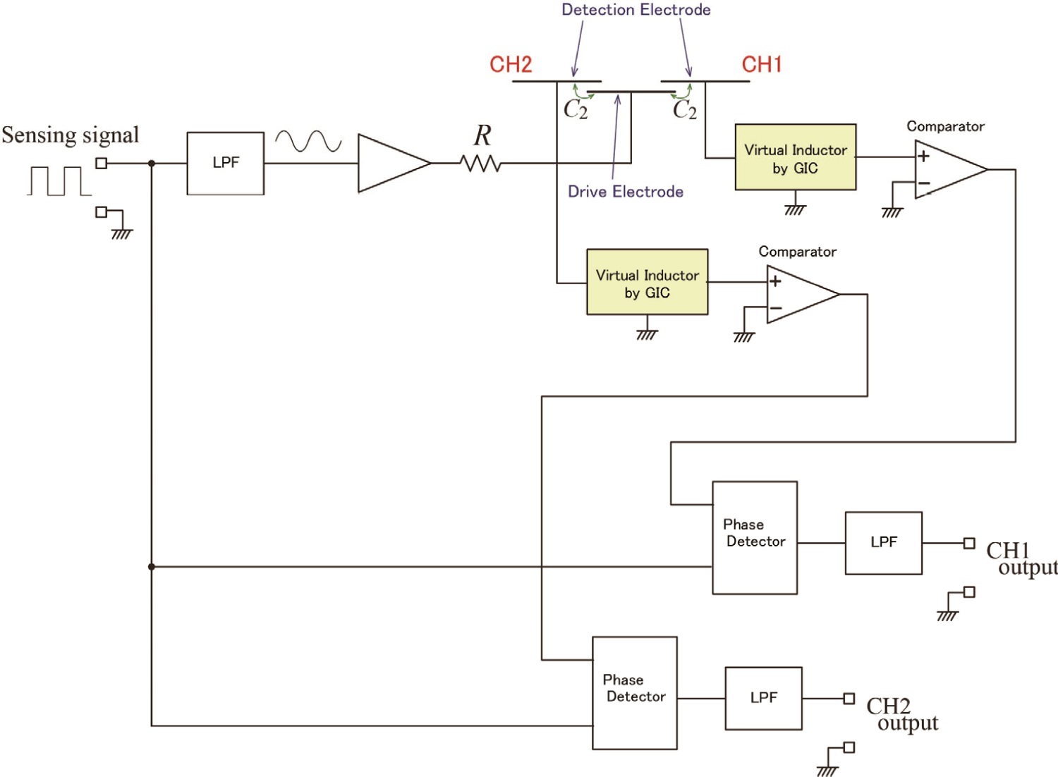
Figure 3: (Color online) Circuit for directional....
(Color online) Circuit for directional proximity sensing.
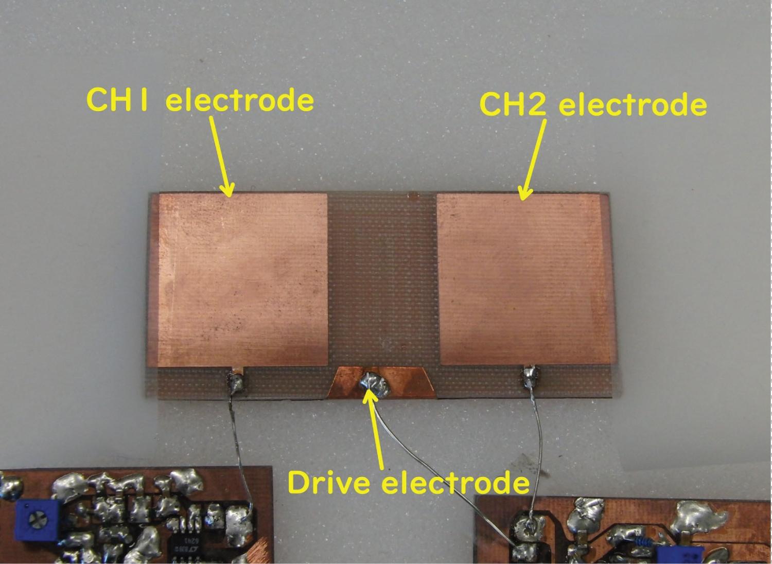
Figure 4: (Color online) Experimental two-electrode....
(Color online) Experimental two-electrode sensor.
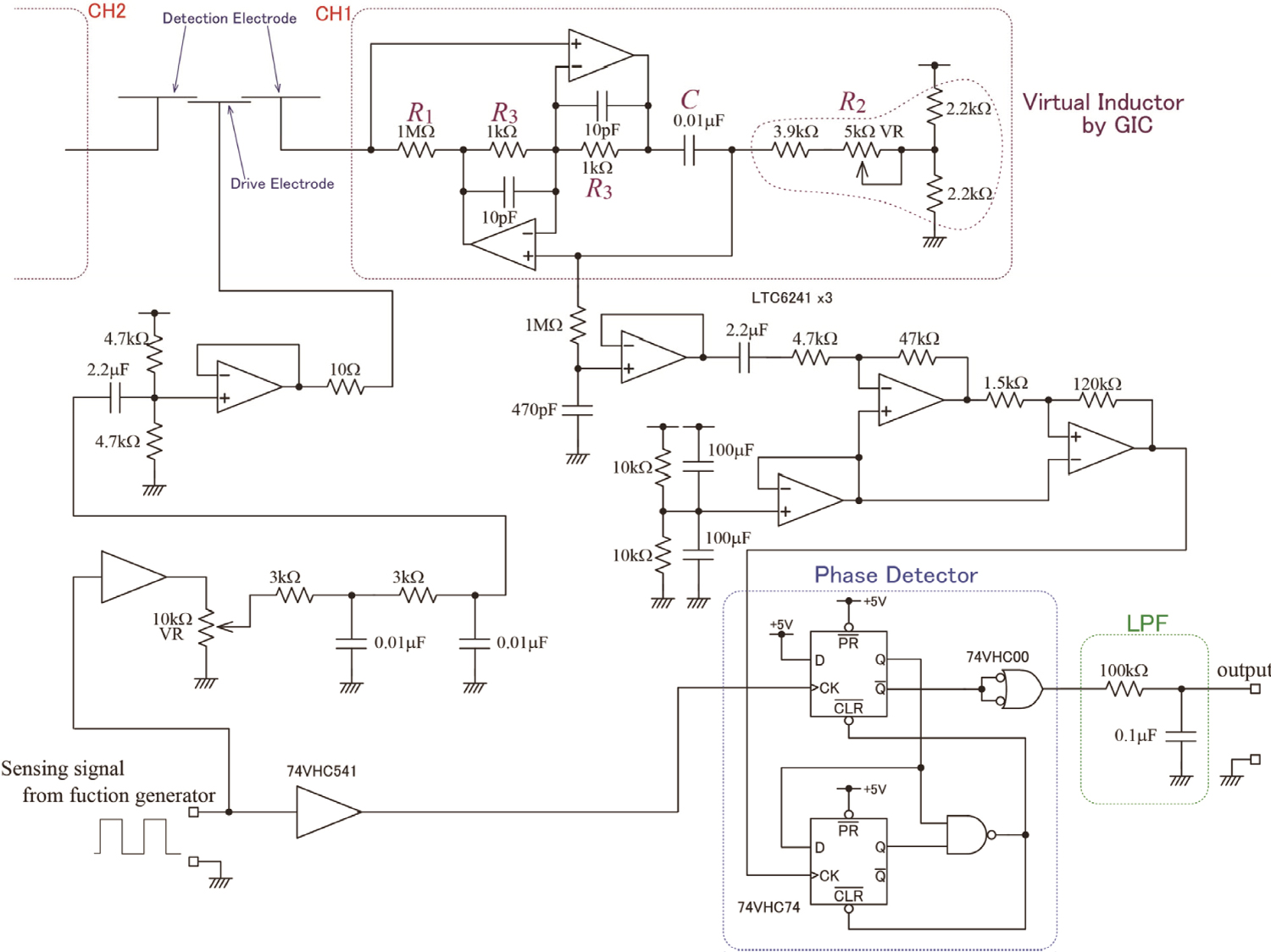
Figure 5: (Color online) Sensing circuit used....
(Color online) Sensing circuit used in the experiments.
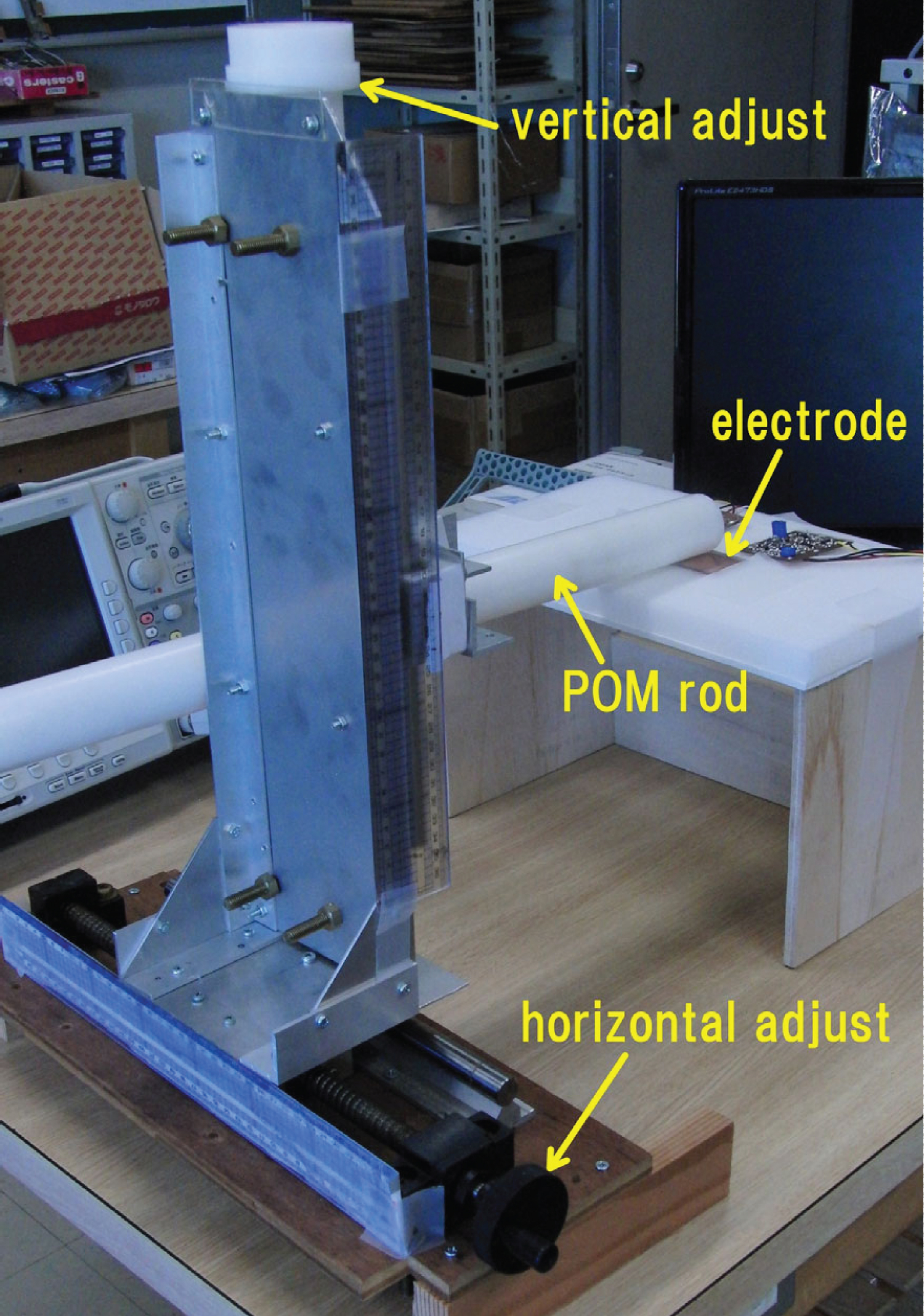
Figure 6: (Color online) Experimental setup for....
(Color online) Experimental setup for two-electrode sensor.

Figure 7: (Color online) Dependence of LPF output on two-dimensional...
(Color online) Dependence of LPF output on two-dimensional position of the plastic rod.

Figure 8: (Color online) Dependence of LPF output...
(Color online) Dependence of LPF output on distance from electrode.
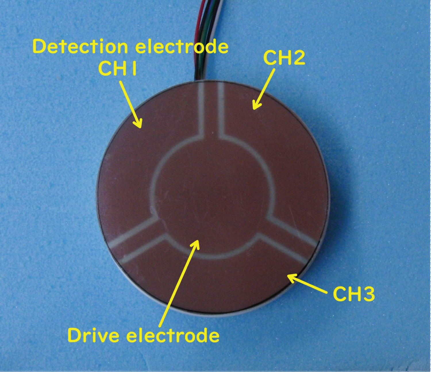
Figure 9: (Color online) Electrode for three-dimensional....
(Color online) Electrode for three-dimensional proximity sensing.

Figure 10: (Color online) Experimental setup for the demonstration...
(Color online) Experimental setup for the demonstration of three-dimensional proximity sensing.
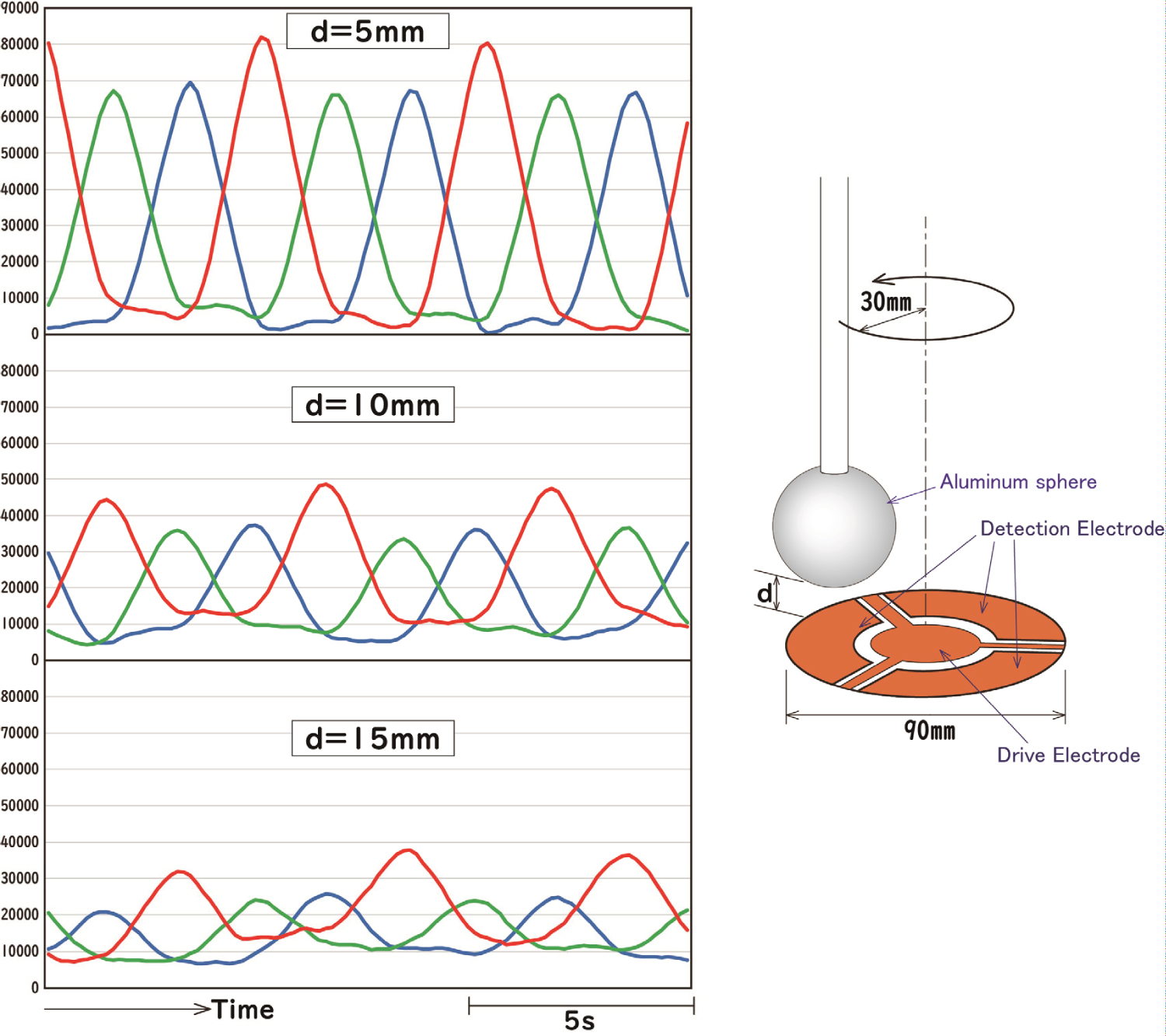
Figure 11: (Color online) Example of output waveform when a metal....
(Color online) Example of output waveform when a metal sphere horizontally rotated over the center of the electrode board.

Figure 12: (Color online) Series resonance proximity...
(Color online) Series resonance proximity sensing using GIC virtual inductor.
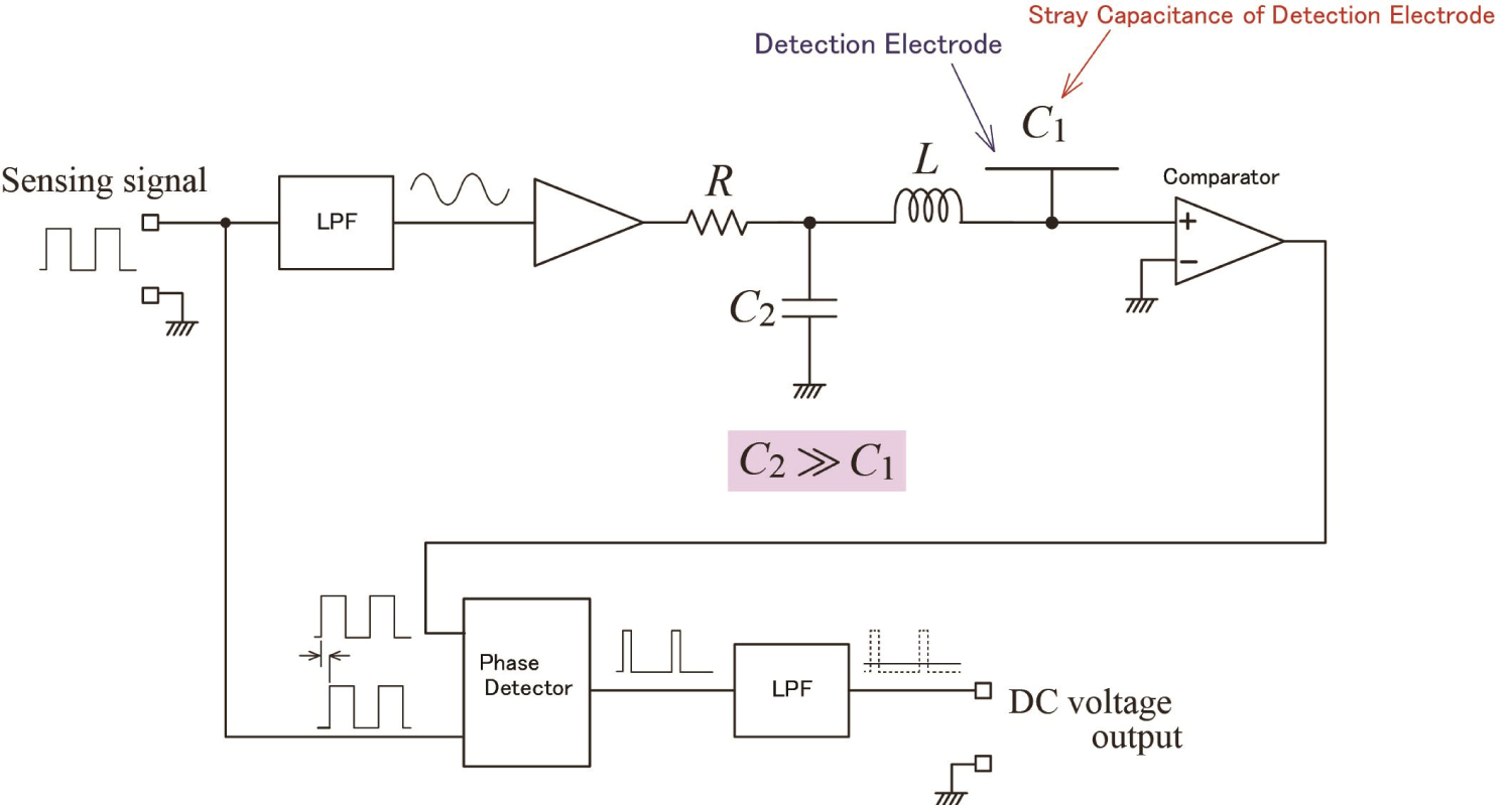
Figure 13: (Color online) Series resonance proximity....
(Color online) Series resonance proximity sensing using a coil.
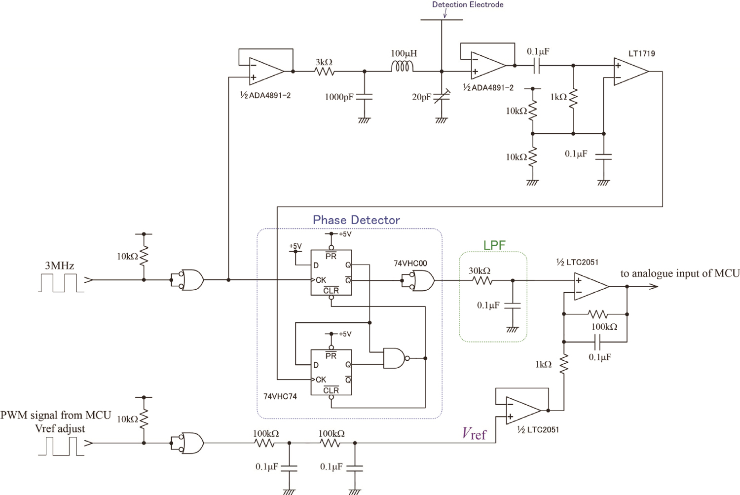
Figure 14: (Color online) Circuit diagram of series...
(Color online) Circuit diagram of series resonance proximity sensing using a coil.
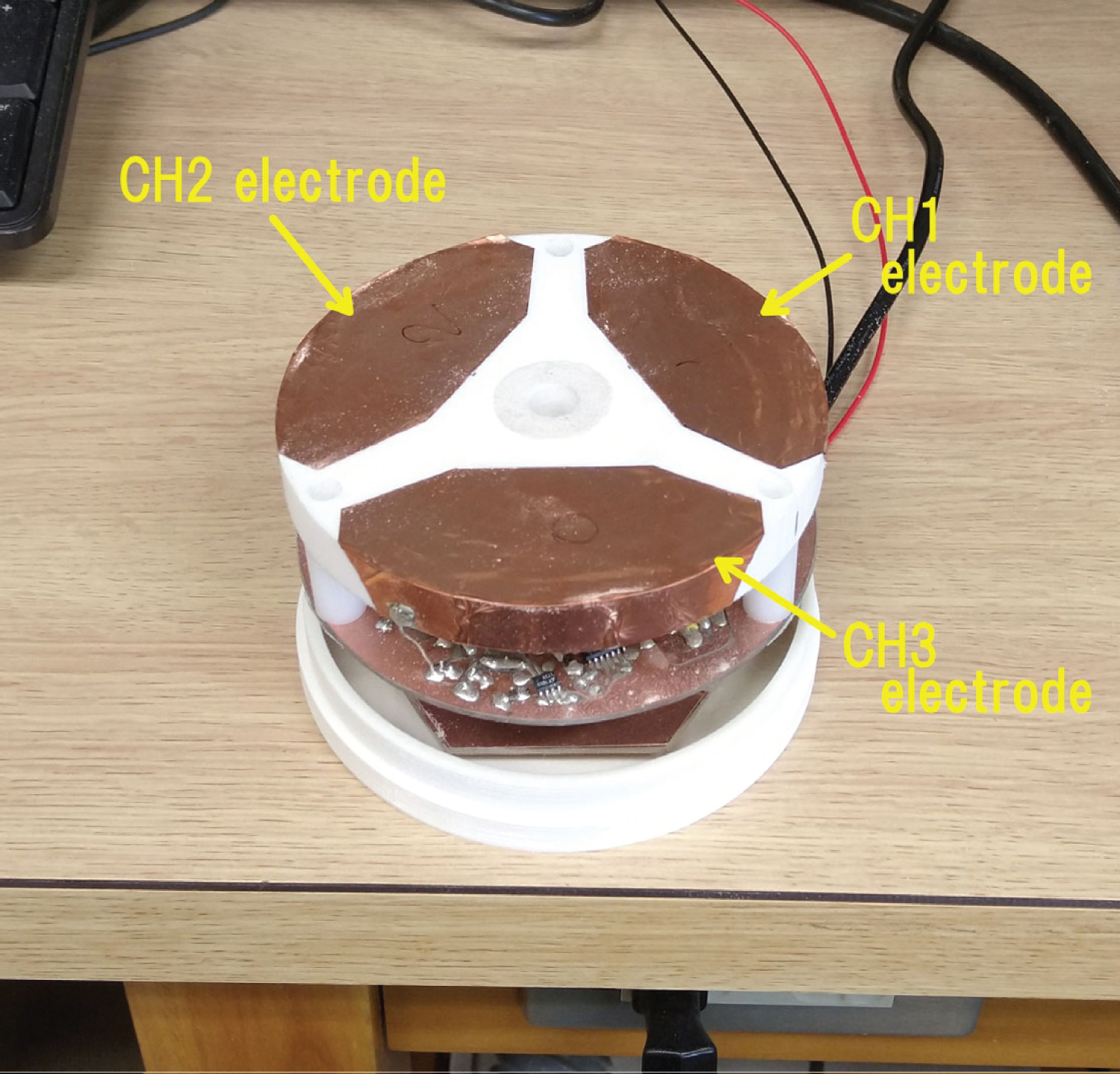
Figure 15: (Color online) Experimental 3D proximity....
(Color online) Experimental 3D proximity sensor (series resonance type).
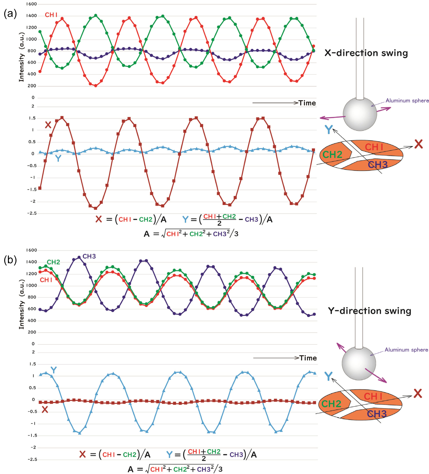
Figure 16: (Color online) Example of signal wave forms....
(Color online) Example of signal wave forms and calculated coordinates when an aluminum sphere was swung over the electrodes: (a) Swing in the horizontal direction; (b) Swing in the vertical direction.
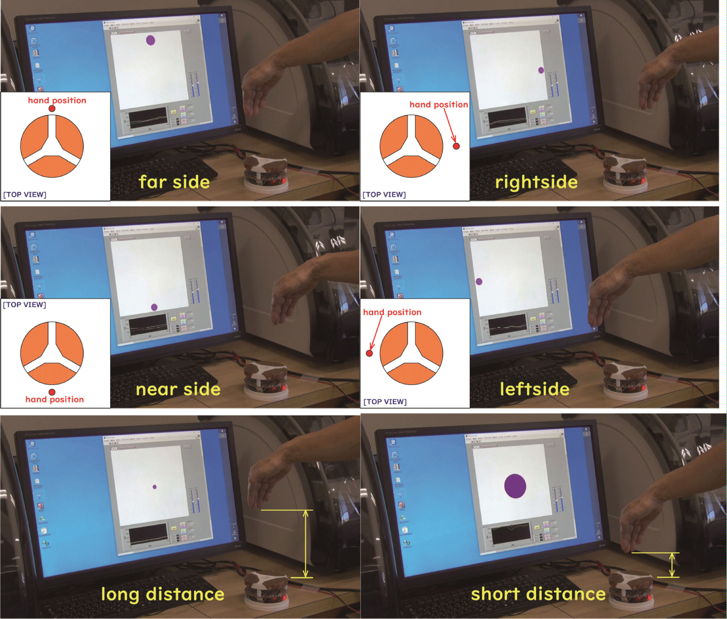
Figure 17: (Color online) Screen display of...
(Color online) Screen display of human hand position.
References
- Z Chen, RC Luo (1998) Design and implementation of capacitive proximity sensor using microelectromechanical systems technology. IEEE Transactions on Industrial Electronics 45: 886-894.
- SW Badelt, AP Blaisdell (2008) Capacitive sensors for detecting proximity and response. Behav Res Methods 40: 613-621.
- X Hu, W Yang (2010) Planar capacitive sensors-designs and applications. Sensor Review 30: 24-39.
- HK Kim, S Lee, KS Yun (2011) Capacitive tactile sensor array for touch screen application. Sensors and Actuators A: Physical 165: 2-7.
- S Kim, W Choi, W Rim, Y Chun, H Shim, et al. (2011) A highly sensitive capacitive touch sensor integrated on a thin-film- encapsulated active-matrix oled for ultrathin displays. IEEE Transactions on Electron Devices 58: 3609-3615.
- CS Sander, JW Knutti, JD Meindl (1980) A monolithic capacitive pressure sensor with pulse-period output. IEEE Transactions on Electron Devices 27: 927-930.
- O Akar, T Akin, K Najafi (2001) A wireless batch sealed absolute capacitive pressure sensor. Sensors and Actuators A: Physical 95: 29-38.
- FN Toth, GCM Meijer (1992) A low-cost, smart capacitive position sensor. IEEE Transactions on Instrumentation and Measurement 41: 1041-1044.
- HU Meyer (1996) An integrated capacitive position sensor. IEEE Transactions on Instrumentation and Measurement 45: 521-525.
- C Burbaum, J Mohr, P Bley, W Ehrfeld (1991) Fabrication of capacitive acceleration sensors by the LIGA technique. Sensors and Actuators A: Physical 27: 559-563.
- X Li, GW De Jong, GCM Meijer, FN Toth, FML Van Der Goes (1997) Low-cost cmos interface for capacitive sensors and its application in a capacitive angular encoder. In: JH Huijsing, GCM Meijer, Smart Sensor Interfaces, Springer, Boston, MA, USA, 61-71.
- T Fabian, G Brasseur (1998) A robust capacitive angular speed sensor. IEEE Transactions on Instrumentation and Measurement 47: 280-284.
- PJ Schubert, JH Nevin (1985) A polyimide-based capacitive humidity sensor. IEEE Transactions on Electron Devices 32: 1220-1223.
- FN Toth, GCM Meijer, M van der Lee (1997) A planar capacitive precision gauge for liquid-level and leakage detection. IEEE Transactions on Instrumentation and Measurement 46: 644-646.
- M Deguchi (2020) A simple method for detecting very small changes in capacitance or inductance. Microelectronics Journal 101: 104802.
- L Zalud, P Kocmanova, F Burian, T Jilek, P Kalvoda, et al. (2015) Calibration and evaluation of parameters in a 3D proximity rotating scanner. ELEKTRONIKA IR ELEKTROTECHNIKA 21: 3-12.
- K Ohno, T Kawahara, S Tadokoro (2009) Development of 3D laser scanner for measuring uniform and dense 3D shapes of static objects in dynamic environment. 2008 IEEE International Conference on Robotics and Biomimetics, 2161-2167.
- A Peiravi, B Taabbodi (2010) A reliable 3d laser triangulation-based scanner with a new simple but accurate procedure for finding scanner parameters. Journal of American Science 6: 80-85.
- T Ogawa, H Sakai, Y Suzuki, K Takagi, K Morikawa (2011) Pedestrian detection and tracking using in-vehicle lidar for automotive application. 2011 IEEE Intelligent Vehicles Symposium (IV), 734-739.
- T Fersch, R Weigel, A Koelpin (2017) A CDMA modulation technique for automotive time-of-flight LiDAR systems. IEEE Sensors Journal 17: 3507-3516.
- ME Warren (2019) Automotive LIDAR technology. 2019 Symposium on VLSI Circuits, 254-255.
- S Hussmann, T Edeler (2009) Performance improvement of a 3D-TOF PMD camera using a pseudo 4-phase shift algorithm. IEEE Instrumentation and Measurement Technology Conference, 542-546.
- SLX Francis, SG Anavatti, MA Garratt (2011) Reconstructing the geometry of an object using 3D TOF Camera. IEEE Workshop on Merging Fields of Computational Intelligence and Sensor Technology, 13-17.
- B Langmann, K Hartmann, O Loffeld (2012) Depth camera technology comparison and performance evaluation. (1st edn), Proceedings of the International Conference on Pattern Recognition Applications and Methods, 438-444.
- M Keller, A Kolb (2009) Real-time simulation of time-of-flight sensors. Simulation Modeling Practice and Theory 17: 967-978.
- S Foix, G Aleny, C Torras (2011) Lock-in time-of-flight (ToF) Cameras: A survey. IEEE Sensors Journal 11: 1917-1926.
- JW Weingarten, G Gruener, R Siegwart (2004) A state-of-the-art 3D sensor for robot navigation. Proceedings of the 2004 IEEE/RSJ International Conference on Intelligent Robots and Systems (IROS) 3: 2155-2160.
- GestIC Design Guide. Microchip Technology Inc., DS40001716C.
Author Details
Mikio Deguchi*
Department of Electronics and Control Engineering, National Institute of Technology (KOSEN), Niihama College, Japan
Corresponding author
Mikio Deguchi, Department of Electronics and Control Engineering, National Institute of Technology, 7-1 Yagumocho, Niihama, Ehime 792-8580, Japan.
Accepted: November 02, 2020 | Published Online: November 04, 2020
Citation: Deguchi M (2020) Three-Dimensional Proximity Sensing with Simple Circuit Made of General-Purpose Electronic Components. Int J Electron Device Phys 4:008
Copyright: © 2020 Mikio Deguchi M. This is an open-access article distributed under the terms of the Creative Commons Attribution License, which permits unrestricted use, distribution, and reproduction in any medium, provided the original author and source are credited.
Abstract
A simple method for three-dimensional proximity sensing with an electronic circuit composed of only general-purpose electronic components is presented. Three detection electrodes are triangularly arranged at regular intervals. Changes in the stray capacitance of each electrode due to the proximity of an object are observed. This method to detect a slight change in capacitance takes advantage of the fact that the transfer characteristics of a circuit comprising three reactance elements has the property of sharp phase changes near the resonance frequency. The position of an object is estimated from the balance of the signals of three channels, and its distance is determined from their magnitude. This method enables the three-dimensional proximity detection of an object. Especially, this method can be used to electronically recognize the gestures of a human hand with low-cost circuitry.
Keywords
Capacitive sensor, Object detection, Proximity sensor, Three-dimensional sensing
Introduction
Capacitive sensors are widely used in both industrial and consumer products [1-14]. For example, capacitive proximity sensors play an important role in handling objects in factory production lines. Also, in more familiar areas, capacitive sensors are used in touch panels for smartphones and tablet computers. Capacitive sensors detect slight changes in the capacitance of the electrodes. Several principles can be applied to achieve this detection method.
One (principle A) is charging the capacitor and converting the capacitance to voltage or time, using the relationship Q = CV, where Q, C, and V are the charge stored in the capacitor, the capacitance of the capacitor, and the voltage across the capacitor, respectively. Another method (principle B) is to apply an AC signal of a certain frequency to the electrodes and detect changes in impedance due to changes in capacitance.
Finally, a third method (principle C) uses the resonance with an inductor of known inductance. The change in capacitance can be detected as a change in the resonance frequency. Principle C is further divided in two ways. One way is to incorporate a resonance tank into an oscillation circuit and observe changes in the oscillation frequency. The other is to apply a fixed frequency signal to the resonance tank and examine the voltage across the resonance tank. The latter is employed in the method proposed in this article.
The author previously proposed a simple method to detect very small changes in capacitance with an electronic circuit composed of only general-purpose electronic components [15]. When a fixed frequency signal is applied to a circuit that includes three reactance elements, the phase of the voltage across the resonance tank sensitively changes when the capacitance changes. By taking advantage of this property, a capacitive proximity sensor can be configured by combining only general-purpose electronic components. This article uses this principle to describe a simple method of three-dimensionally detecting the proximity of an object, that is, a method that can simultaneously estimate the distance to and direction of an approaching object.
Several techniques are available for three-dimensional (3D) proximity sensing. 3D scanners [16-18] can capture the surrounding situation in three dimensions and are used in various fields. Light detection and ranging technology [19-21] currently play an important role in automatic vehicle driving technology. A time-of-flight camera [22-27] can obtain a 3D image of an object surface, and it is used in gestural interface devices, such as Microsoft Kinect and Leap Motion Controller. These are optical sensing technologies that require sophisticated devices.
As an example of a simpler device, Microchip Inc. provides GestIC [28], which is based on capacitive sensing and allows realization of user interface applications by detection, tracking, and classification of a user's hand gestures in free space. GestIC devices use a transmission signal at a low frequency in the range of 100 kHz and observe the received signals at four or five electrodes. Although the details of the circuit in the IC chip are proprietary, it is thought that changes in the balance of the capacitances between the electrodes due to the proximity of an object are observed from changes in the signal strength of the receiving electrodes, which is an implementation of principle B.
The proposed method in this article, which is based on principle C, can realize performance similar to that of GestIC technology with a simpler circuit comprising only general-purpose electronic components. In the next section, the principle of directional proximity sensing in the proposed method is described, and it is followed by sections that describe experiments on 3D proximity sensing.
Principle of Directional Proximity Detection
In reference [15], the author describes a method that can detect minute changes in capacitance with a simple electronic circuit consisting of only general-purpose electronic components. The proximity sensing method proposed in this article is based on the same measurement principle, as shown in Figure 1. A sensing signal is applied to a network composed of R-C2-(C1//L). The frequency of the sensing signal is set to the frequency near the resonance frequency between L and C1 + C2. The voltage across a resonance tank composed of C1 and L is picked up and waveform-shaped by the comparator and digitized. The phase difference between the original sensing signal and the voltage across C1 and L is detected by the phase detector and converted to a DC voltage signal by a low-pass filter (LPF). When the capacitance of C1 changes, the phase of the voltage across C1 and L sensitively changes.
If the electrode of C1 is exposed to free space as a detection electrode, the capacitance C1 consists of the stray capacitance of the detection electrode. When an object approaches the detection electrode, the stray capacitance C1 increases, because the permittivity of the object is larger than that of air. This change can be detected by observing the phase change of the voltage across C1 and L. To increase the sensitivity of the phase change of the voltage across C1 and L, it is advantageous that C2 is much smaller than C1 and the inductance L is larger. However, when the inductance L is implemented as a coil, it is difficult to realize a high quality factor and a large inductance at the same time.
To eliminate this dilemma, L is implemented as a virtual inductor composed of a general impedance converter (GIC). Figure 2 shows the schematic of a proximity sensing circuit based on this idea, where C1 is the stray capacitance of the detection electrode and L in Figure 1 is replaced with a GIC circuit. The GIC is composed of two operational amplifiers (op-amps) and five impedance elements. The GIC circuit illustrated in Figure 2 is equivalent to an inductor with an inductance of CR1R2. In comparison to a coil, it is easier to realize a capacitor and a resistor that are closer to the ideal circuit model. By adjusting the values of C, R1, and R2, the equivalent inductance value can be set arbitrarily.
When an object approaches the detection electrode, its' stray capacitance increases. The increment depends on parameters such as the permittivity, size, and shape of the object and the distance between the object and the detection electrode. If the permittivity, size, and shape of the object are known, it is possible to estimate the distance from the detection electrode. If multiple detection electrodes are provided, the position of the object can be obtained using the principle of triangulation.
To validate the principle of this detection method, an experiment was conducted with two detection electrodes. Figure 3 shows the schematics of the electronic circuit used for the experiment. Capacitance C2 is formed between each detection electrode and driving electrode. Figure 4 is a photograph of the electrodes used in the experiment. Each detection electrode is a 30-mm square copper film pattern formed on a 1.6-mm thick FR-4 print circuit board. The gap between the two detection electrodes is 2 cm. The driving electrode is an adhesive copper film attached on the back side of the printed circuit board.
A diagram of the electronic circuit is shown in Figure 5. The circuit was powered by a single 5-V supply. The op-amps used for the GIC were model LTC6241, which is a low-noise rail-to-rail CMOS op-amp. The high input impedance of CMOS op-amps is suitable for realizing high quality in the GIC virtual inductor. In this circuit, the equivalent inductance was about 100 H and could be adjusted by a 5-k Ω potentiometer (a part of R2). Because such a large inductance can be obtained, this GIC can be also called a giant inductance circuit. The right-side terminal voltage of the potentiometer was pulled up and down by two 2.2-k Ω resistors. This makes the analogue GND for the signal in GIC circuit the center of the 5-V supply rail.
The voltage across C1 and the virtual inductor is picked up as the voltage at the point between C and R2, magnified by 10 times, and digitized by a comparator. The phase difference between the original sensing signal and the digitized signal was detected by a phase detector composed of two D-type flip-flop circuits and a NAND gate. The phase detector generated pulses, the widths of which represented the phase difference. These pulses were converted to DC voltage signal by a LPF comprising a 100-kΩ resistor and 0.1- μF capacitor.
The sensing signal was provided by a function generator. The sensing signal was initially a digital pulse at the transistor-transistor logic level. Before this signal was applied to the driving electrode, the LPF, consisting of 3-kΩ resistors and 0.01-μF capacitors, weakened the harmonic components and makes the waveform round. The frequency of the sensing signal was 2.7 kHz.
Figure 6 is a photograph of the experimental setup. A plastic (polyoxymethylene, or POM) rod 40 mm in diameter was horizontally held above the electrodes. The height and the horizontal position of the plastic rod could be separately adjusted by rotating knobs.
Figure 7 shows the dependence of the LPF output on the position of the plastic rod. At x = -2.5 cm, the plastic rod was immediately above the center of the CH1 electrode. Similarly, at x = 2.5 cm, the plastic rod was over the center of the CH2 electrode. The LPF output reached its maximum value when the plastic rod was directly above the center of each electrode. The characteristics of both channels were substantially symmetrical, although there was a slight difference in sensitivity and offset. The LPF output decreased as the distance from the electrode increased.
Figure 8 shows the dependence of the LPF output on the distance of the plastic rod from the electrode when the rod is over the center of the electrode. The LPF output seems to almost exponentially decrease toward a constant value according to the distance from the electrode. The increment with respect to the limit value when the distance is infinite can be used as an indicator of the distance from the electrode. The detectable range of object distance depends on how much this increment is amplified. Figure 8 plots the raw value of the LPF output. With an assumed detection threshold of 25 mV, the detectable range was about 15 mm without amplification in this case.
The results of Figure 7 and Figure 8 show that it is possible to estimate the direction to the object from the balance of outputs of two channels and to estimate the distance based on the magnitude of the outputs. Because the magnitude of the outputs depends on properties of the target object, such as size, shape, and permittivity, it is necessary to obtain the scaling law in advance to know the exact distance of the object.
Three-Dimensional Proximity Sensing
The experiment described in the previous section demonstrated the feasibility of estimating both the direction of and distance to an object with two electrodes. It follows that, if multiple electrodes are employed, for example, three or more, the 3D position of an object above the electrodes can be estimated.
Figure 9 is a photograph of the electrodes used in the experiment to verify this idea of determining the position. The detection electrodes were patterned on the surface of an FR-4 circuit board 90 mm in diameter. Three detection electrode areas were symmetrically arranged around the center. The driving electrode was patterned on the same surface with the detection electrodes. The gap between the detection electrode and the driving electrode was 2 mm. Because of this coplanar alignment of electrodes, C2 is considered to be very small, which is advantageous for enhancing the sensitivity.
Although the electronic circuit was substantially identical to that in Figure 5, the sensing signal was generated by a microcomputer (PIC18F26K83) and the pulse width of the output of the phase detector was directly measured by the timer module in the microcomputer without conversion to a DC voltage by the LPF. The frequency of the sensing signal was about 4 kHz. The data from the three channels were transmitted to a personal computer and displayed on the screen as a graph.
Figure 10 shows a photograph of the experimental setup for the demonstration of 3D proximity sensing. An aluminum sphere 40 mm in diameter was attached to the bottom edge of a vertically held plastic rod. This plastic rod was mounted on a disk that was slowly rotated by a motor about a vertical axis suspended over the center of the electrode board. The aluminum sphere was insulated by the plastic rod and was electrically floating.
Examples of the output waveform are shown in Figure 11. The radius of the rotation was 30 mm, as illustrated in the figure. The vertical axis of each graph is the increment of the signal with respect to the value when nothing was above the electrodes. The horizontal axis is time. The signal of each of three channels changed periodically and showed a phase 120° different from the other two channels, producing a waveform similar to that of three-phase AC voltage. The period of the signal (about 5s) corresponded to the rotation period of the aluminum sphere. The difference in signal amplitudes is considered to be due to reasons such as the alignment error of the rotation center with respect to the center of the electrode board, the rotation axis not being completely vertical with respect to the electrode board, and the difference in sensitivity of each channel. The signal amplitude decreased as the gap between the aluminum sphere and the electrode board increased.
From this experimental result, it is possible to estimate the direction of an object using the balance of the three signals and to estimate the distance to it using the magnitude of the signals. The signal magnitude also depends on the material, size, and shape of the object. Therefore, to accurately specify the position of the object, it is necessary to assume these parameters and obtain the scaling law in advance. This sensing method allows the proximity detection to be three-dimensionally directional.
Application to 3D Input Device
The electronic circuit used in the method of proximity sensing described in sections 2 and 3 uses the parallel resonance between C1 (stray capacitance of the detection electrode) and L (the GIC virtual inductance). The same function can be achieved using the series resonance between C1 and L, which has a duality relationship with the configuration shown in Figure 1. In this case, the circuit in Figure 2 was modified to form the circuit shown in Figure 12. In the case of series resonance configuration, C2 must be much larger than C1 and C1 is the capacitance between the detection electrode and the driving electrode. If the stray capacitance of the detection electrode is Cs, the characteristic frequency of the phase change is substantially determined by the resonance frequency between L and C1 + Cs. It follows that the sensing function can be realized in the same manner as the configuration of Figure 2.
When the series resonance configuration is used, a higher resonance frequency is advantageous for higher sensitivity. If the resonance frequency is high, it is not necessary to implement L as a GIC virtual inductor. A higher operating frequency is considered to be advantageous for extending the detection range. Figure 13 shows a schematic of series resonance proximity sensing using a coil as the inductor L. In this configuration, the position of C1 and L is exchanged compared with that in Figure 12. This provides the DC connection between the sensing signal driver output and the comparator input, which is convenient for the single-power-supply operation of the circuit.
Figure 14 shows the circuit diagram for one of the three channels using a 100- μ H micro-inductor as L. The sensing signal was generated by a 12-MHz crystal oscillator, and a prescaler divided the frequency by four to produce a sensing signal frequency of 3 MHz. The difference between the LPF output and the reference voltage Vref was amplified and measured by an analog-to-digital converter in a microcomputer. Vref was adjusted by the duty ratio of the pulse-width modulation signal generated by the microcomputer. The 3D proximity sensor shown in Figure 15 was configured by combining three channels.
The detection electrode for each channel was made by attaching adhesive copper film to a POM disk, the diameter and thickness of which were 110 mm and 13 mm, respectively. The position of an object was calculated from the balance of the outputs of three channels. The horizontal direction was calculated from the ratio of CH1 and CH2. The vertical direction was calculated from the ratio of CH3 and the average value of CH1 and CH2. The distance was determined by the root-mean-square value of outputs of three channels. The horizontal and vertical coordinates were corrected according to the distance.
Figure 16 shows an example of three channel signals when an aluminum sphere was swung over the electrodes. An aluminum sphere identical to that in Figure 10 was attached to the lower end of a plastic rod 35 cm long and swung like a pendulum with the upper end of the plastic rod as a fulcrum. The gap between the aluminum sphere and the electrode plate was 3 cm, and the swing amplitude was about 2 cm. The aluminum sphere was electrically floating. Figure 16a shows the signal waveform when the swing was in the horizontal direction. The lower graph shows the waveform of the calculated values of the X-coordinate and Y-coordinate. The formula for the calculation is shown in the figure. In this case, the X-coordinate value varied almost sinusoidally, and the Y-coordinate value was almost constant. Similarly, Figure 16b shows the waveforms when the swing was in the vertical direction. The X-coordinate value was almost constant, and the Y-coordinate value varied almost sinusoidally in this case. These results show that the position of the object in the plane parallel to the electrode plate can be calculated from the three channel signals.
The photographs in Figure 17 show how the position of a human hand is recognized by this 3D directional proximity sensor and displayed. On the screen, the position of the hand was shown with a circle and the distance was represented by the diameter of the circle. The direction of the hand was calculated based on the balance of signals of three channels, and the distance was determined by the root-mean-square value of them. The detection range was estimated to be 20 cm or more. However, because the frequency of the sensing signal was on the order of megahertz, which is in the so-called radio frequency range, attention must be paid to the influence on the surroundings due to electric field leakage.
This sensor can be applied to non-contact input devices that point and operate objects with gestures. Conventionally, a sensing device, such as a 3D camera, or an application- specific integrated circuit (IC), such as GestIC, is required to realize such a function. Being able to achieve the same thing with a simple electronic circuit is considered to be advantageous in reducing cost and improving flexibility in the device design.
Discussion
To extend the detection range for capacitive proximity sensing, it is necessary to extend the electric field as far as possible. However, increasing the extent of the electric field means increasing the risk of electromagnetic interference with nearby devices. Thus, increasing the detection sensitivity and minimizing the leakage of electromagnetic fields to the outside has a trade-off relationship.
In this respect, the method described in sections 2 and 3, in which the operating frequency is low, on the order of several kilohertz or less, is considered to produce substantially negligible electromagnetic wave radiation from the detection electrode. Moreover, due to LC resonance, the voltage in the electrode contains almost no harmonics, and the influence of harmonics can be ignored. The low operating frequency also widens the range of usable circuit components, which is advantageous for reducing the cost of the circuit.
The series resonance type circuit described in section 4 has a much higher operating frequency, which is advantageous for extending the detection range. However, a higher frequency increases the risk of electromagnetic interference. For the circuit shown in Figure 14, a frequency 3 MHz was chosen to avoid interference with medium-wave radio set.
Implementing the inductor as a GIC virtual inductor provides the advantage of low operating frequency and flexibility in the circuit design. However, because semiconductor devices (two op-amps) are used in the GIC, its induction property is significantly affected by temperature. Therefore, if more accurate measurement is required, it may be necessary to measure the temperature and give appropriate feedback, or to correct the measured value.
In the circuits shown in Figure 5 and Figure 14, the peak-to-peak value of the signal that drives the driving electrode is 5 V at most, which is the supply voltage. In the proposed method, because a change in the phase of the resonant signal is observed, the amplitude of the driving signal is not important for the sensitivity. However, the capacitance C2 in Figure 2 can be reduced, and the capacitance C2 in Figure 13 can be increased by increasing the amplitude of the driving signal, which can be expected to improve sensitivity. For example, if a RS-232C line driver IC is used, the amplitude of the driving voltage can be increased greatly to extend the detection range.
The detection range also depends on the size and shape of the detection electrodes and how they are arranged. The larger the electrode, the wider the spread of the electric field and the wider the detection range. In the experiments described in sections 3 and 4, the electrodes were designed to detect a human hand with sufficient sensitivity.
Considering the potential for industrial use as a sensor unit for instrumentation, it is desirable to make the overall size of the sensor as small as possible. To reduce the size of the electrode board without reducing the area of the electrode region, the gap between the electrodes must be narrowed. However, if the gap between the electrodes is too narrow, they may interfere with each other, and the signal may be affected by the signals of other channels. As shown in Figure 9, the arrangement in which the detection and driving electrodes are on the same surface and a region for the driving electrode is provided between the detection electrodes is effective for reducing interference between channels.
The directional proximity sensors in the experiments had three channels and three detection electrodes. Using four channels and arranging detection electrodes as pairs in each of the vertical and horizontal directions would make it possible to estimate the position of the object more accurately. However, as the number of channels increases, it becomes a daunting task to match the sensitivity of all channels.
The 3D proximity sensing method proposed in this article has several advantages. First, the electronic circuit is simple and can be composed entirely from general-purpose electronic components. This is advantageous in terms of reducing the cost as compared with other methods using a 3D camera or other sophisticated devices. In addition, it can be said that it provides more flexibility for sensor design than methods using a dedicated semiconductor device, such as GestIC. Second, the operating frequency can be selected from a wide range on the order of kilohertz to megahertz. If a GIC is used as a virtual inductor, the operating frequency can be set very low, in the audio frequency band. Third, it is difficult to detect an object made of transparent material by optical methods, such as a 3D camera, but the proposed method can detect any substance, including plastic, metal, wood, and living tissue (i.e., human hands). Also, as long as there is no shield blocking the electric field, it is possible to detect an object on the other side of the detector, even if there is something else in between. Fourth, the directivity obtained by the sensor is determined by how the electric field spreads in front of the electrodes, which can be optimized by changing the dimensions and shape of the electrodes, depending on the application (The third and fourth advantages are common features of the capacitive proximity sensing method.). Fifth, although the proposed method in this article is based on capacitive proximity sensing, the same principle can be applied to inductive sensing. By arranging multiple coils instead of arranging multiple electrodes, it is possible to detect the proximity and position information of a conductive material, such as a metal.
Conclusion
The method described in this article makes it possible to construct a capacitive proximity simple sensor, from general-purpose electronic components, that is capable of three-dimensionally capturing the object position and distance from the detector when an object approaches it. The electronic circuit uses the LC resonance of three reactance elements. When implementing the inductor as a GIC virtual inductor, the operating frequency can be set on the order of several kilohertz or less. The proposed method can detect any substance, including plastic, metal, wood, and living tissue (i.e., human hands). Its sensitivity to human hands makes this method applicable to non-contact input devices that point and manipulate objects with gestures without requiring sophisticated devices, such as 3D cameras.