
International Journal of Electronics and Device Physics
(ISSN: 2631-5041)
Volume 5, Issue 1
Research Article
DOI: 10.35840/2631-5041/1710

Article Formats
Design of Chebyshev Bandpass Waveguide Filter for E-band Based on CSRR Metamaterial
Table of Content
Figures
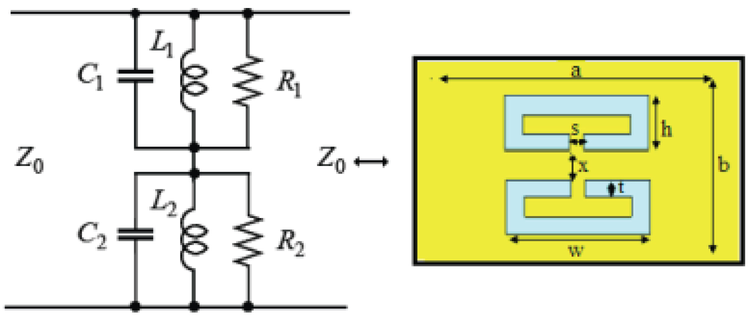
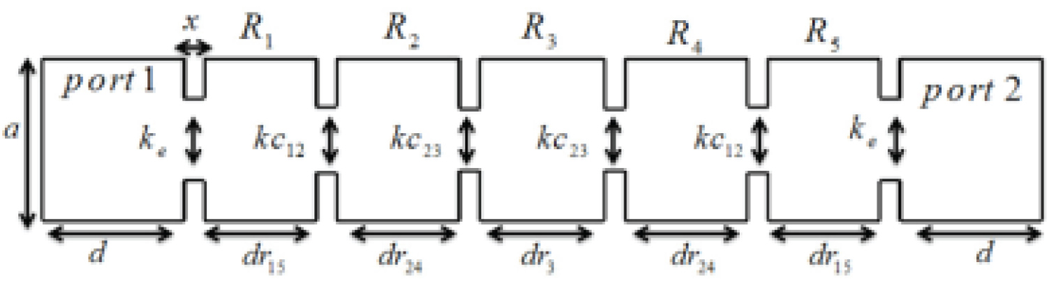

Figure 3: S-parameters comparison between....
S-parameters comparison between conventional and proposed resonator at resonant frequency.
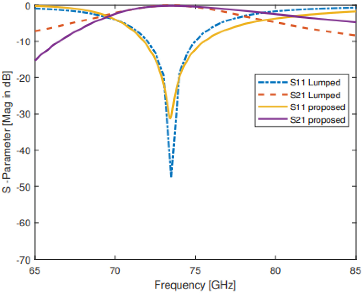
Figure 4: S-parameters comparison between....
S-parameters comparison between lumped element circuit and proposed resonator at resonant frequency.
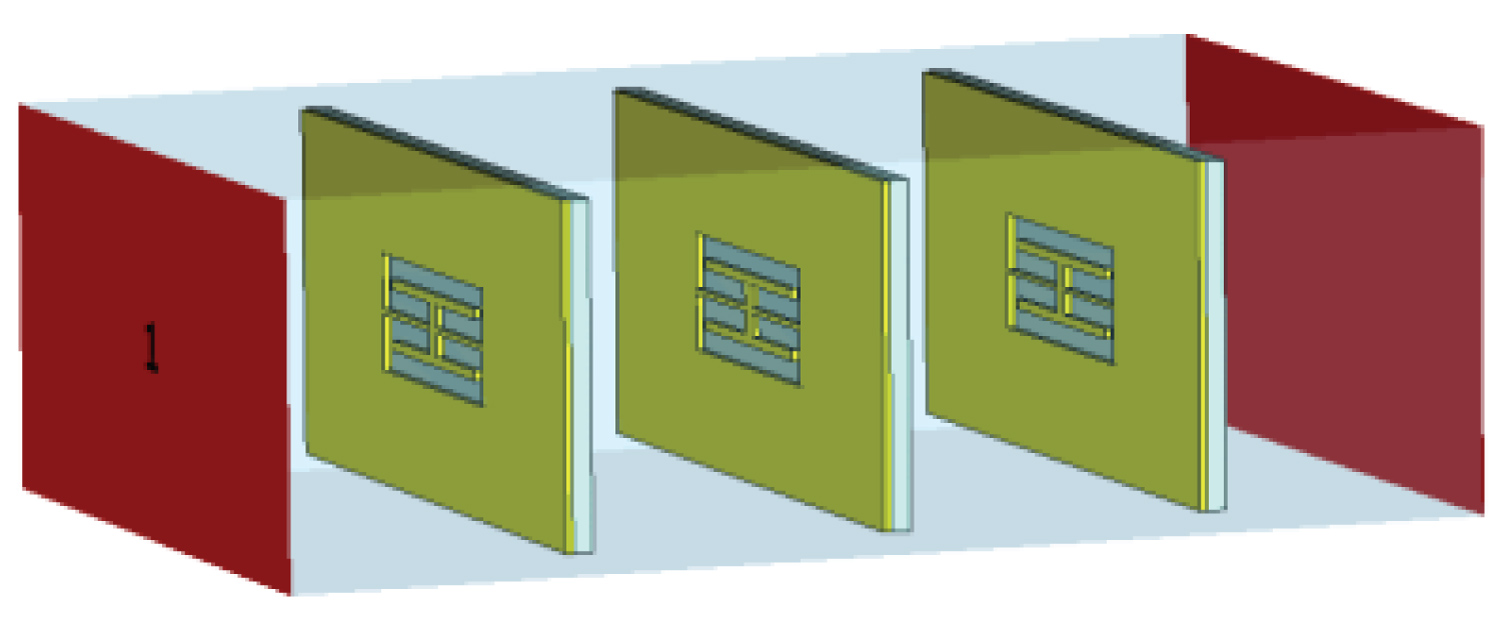
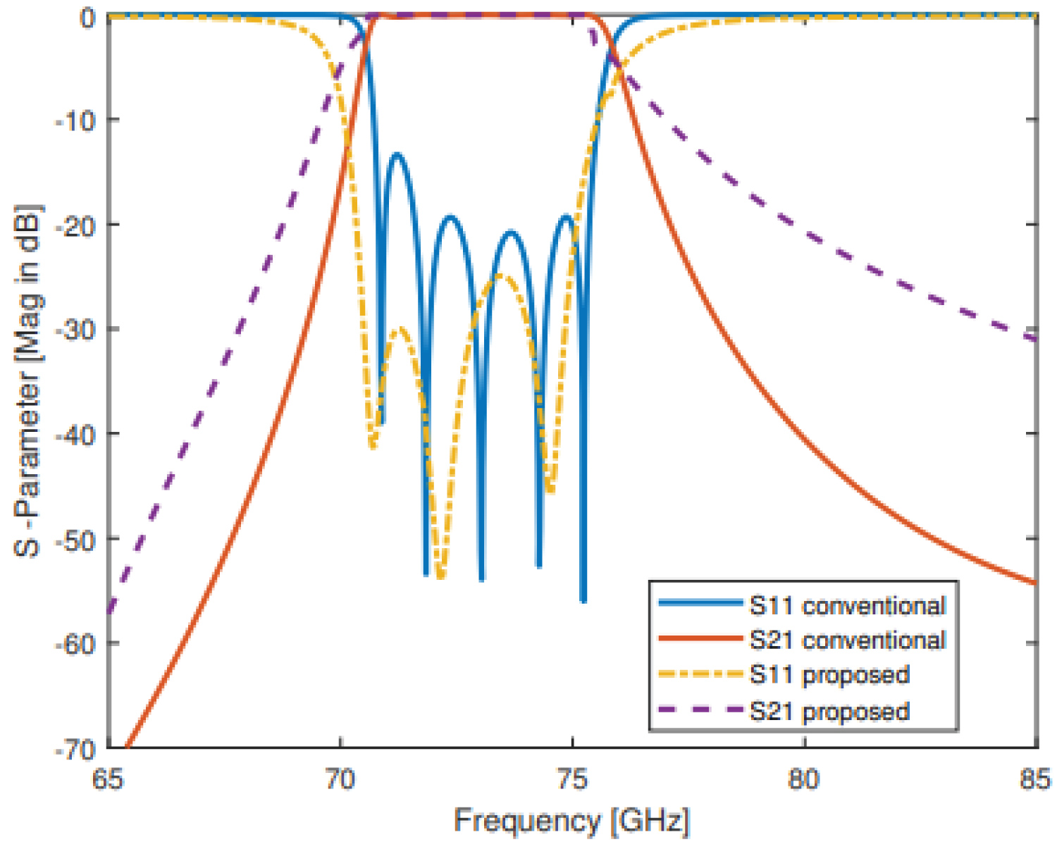
Figure 6: S-parameters comparison between....
S-parameters comparison between conventional and proposed waveguide bandpass filter at 73.5 GHz resonant frequency.
References
- Pozar DM (2012) Microwave engineering. In: Electrical Engineering. (4th edn), Hoboken, NJ, USA: Wiley, 3.2: 102-110.
- Skaik T, Abu Hussain M (2013) Design of diplexers for E-Band communication systems. 2013 13th Mediterranean Microwave Symposium (MMS), Saida, 1-4.
- Atia AE, Williams AE (1972) Narrow-bandpass waveguide filters. IEEE Transactions on Microwave Theory and Techniques 20: 258-265.
- Bonetti RR, Williams AE (1987) Application of dual TM modesto triple and quadruple-mode filters. IEEE Transactions on Microwave Theory and Techniques 35: 1143-1149.
- Abuhussain MM (2013) An e-band diplexer for gigabit wireless communications systems. MS thesis, Elec Eng Dept IUG, Gaza.
- Hong JS, Lancaster MJ (2001) Microstrip filters for rf/microwave applications. In: Electronic, (1st edn), Hoboken, NJ, USA: John Wiley & Sons, 4: 77-87.
- Stander T (2015) A review of key development areas in low-cost packaging and integration of future E-band mm-wave transceivers. AFRICON 2015, Addis Ababa 1-5.
- Boes F, Antes J, Messinger T, Meier D, Henneberger R, et al. (2015) Multi-gigabit E-band wireless data transmission. In 2015 IEEE MTT-S International Microwave Symposium 1-4.
- Frecassetti MGL (2015) E-band and v-band - survey on status of worldwide regulation. ETSI ISG mWT White Paper.
- Chan KY, Ramer R, Mansour RR, Guo YJ (2014) 60 GHz to E-band switchable bandpass filter. IEEE Microwave and Wireless Components Letters 24: 545-547.
- Dilek SM, Henneberger R, Kallfass I (2018) Performance analysis of e-band duplex transceiver based on waveguide diplexer filters. In 2018 48th European Microwave Conference (EuMC) 1069-1072 IEEE.
- Ding DZ, Xu JP (2014) Low conversion loss full E-band seventh-harmonic mixer with compact filter. Electronics letters 50: 526-528.
- Fang D, Zhang B, He J (2016) A E-band E-plane type waveguide bandpass filter. In 2016 IEEE 9th UK-Europe-China Workshop on Millimetre Waves and Terahertz Technologies (UCMMT) 180-182 IEEE.
- Vosoogh A, Sorkherizi MS, Vassilev V, Zaman AU, He ZS, et al. (2019) Compact integrated full-duplex gap waveguide-based radio front end for multi-Gbit/s point-to-point backhaul links at E-band. IEEE Transactions on Microwave Theory and Techniques 67: 3783-3797.
- Xu X, Zhang M, Hirokawa J, Ando M (2016) E-band plate-laminated waveguide filters and their integration into a corporate-feed slot array antenna with diffusion bonding technology. IEEE Transactions on Microwave Theory and Techniques 64: 3592-3603.
- Zhang B, Zirath H (2015) 3D printed iris bandpass filters for millimetre wave applications. Electronics Letters 51: 1791-1793.
- Zhang B, Zirath H (2016) A metallic 3-D printed E-band radio front end. IEEE Microwave and Wireless Components Letters 26: 331-333.
- Zou T, Zhang B, Fan Y (2016) Design of a 73GHz waveguide bandpass filter. In: 2016 IEEE 9th UK-Europe-China Work-shop on Millimetre Waves and Terahertz Technologies (UCMMT), IEEE, 219-221.
- Cohn SB (1957) Direct-coupled-resonator filters. In: Proceedings of the IRE 45: 187-196.
- Pendry JB, Holden AJ, Robbins DJ, Stewart WJ (1999) Magnetism from conductors and enhanced nonlinear phenomena. In IEEE Transactions on Microwave Theory and Techniques 47: 2075- 2084.
- Veselago VG (1968) Electrodynamics of substances with simultaneously negative electrical and magnetic permeabilities. Soviet Physics Uspekhi 10: 504-509.
- Garcia J, Bonache J, Gil I, Martin F, Velazquez-Ahumada MC, et al. (2006) Miniaturized microstrip and CPW filters using coupled metamaterial resonators. In IEEE Transactions on Microwave Theory and Techniques 54: 2628-2635.
- Zhang C, Yin S, Long C, Dong BW, He DP, et al. (2021) Hybrid metamaterial absorber for ultra-low and dual-broadband absorption. Opt Express 29: 14078-14086.
- Hrabar S, Jankovic G, Zivkovic B, Sipus Z (2005) Numerical and experimental investigation of field distribution in waveguide filled with anisotropic single negative metamaterial. 2005 18th International Conference on Applied Electromagnetics and Communications, Dubrovnik, 1-4.
- Liu Y, Ma H (2012) A broadband bandpass rectangular waveguide filter based on metamaterials. 2012 International Workshop on Metamaterials (Meta), Nanjing, 1-4.
- Yelizarov AA, Nazarov IV, Sidorova TV, Malinova OE, Karavashkina VN (2018) Modeling of a waveguide stop-band filter with a mushroom-shaped metamaterial wall and dielectric substrates. 2018 Systems of Signal Synchronization, Generating and Processing in Telecommunications (SYNCHROINFO), Minsk, 1-3.
- Bahrami H, Hakkak M, Pirhadi A (2007) Using complementary split ring resonators (CSRR) to design bandpass waveguide filters. 2007 Asia-Pacific Microwave Conference, Bangkok, 1-4.
- Hidayat MR, Munir A (2016) Rectangular waveguide BPF using split ring resonator metamaterials. 2016 22nd Asia-Pacific Conference on Communications (APCC), Yogyakarta, 604-608.
- Becharef K, Nouri K, Abes T (2019) Enhanced performance of substrate integrated waveguide bandstop filter based on metamaterials SCSRRs. 2019 6th International Conference on Image and Signal Processing and their Applications (ISPA), Mostaganem, Algeria, 1-5.
- Kiumarsi H, Wasa K, Ito H, Ishihara N, Masu K (2015) E-band filters based on substrate integrated waveguide octagonal cavities loaded by complementary split-ring resonators. 2015 IEEE MTT-S International Microwave Symposium, Phoenix, AZ, 1-4.
- Stefanovski SL, Potrebic´ MM, Tos?ic´ DV (2013) Design and analysis of bandpass waveguide filters using novel complementary split ring resonators. 2013 11th International Conference on Telecommunications in Modern Satellite, Cable and Broadcasting Services (TELSIKS), Nis, 257-260.
- Fallahzadeh S, Bahrami H, Tayarani M (2009) A novel dual-band band-stop waveguide filter using split ring resonators. Progress in Electromagnetics Research Letters 12: 133-139.
- Odabasi H, Teixeira FL (2013) Electric-field-coupled resonators as metamaterial loadings for waveguide miniaturization. Journal of Applied Physics 114: 214901.
- Nassar SO, Meyer P (2017) Pedestal substrate integrated waveguide resonators and filters. In: IET Microwaves, Antennas and Propagation, 111: 804-810.
- Torabi Y, Dadashzadeh G, Oraizi H (2016) Miniaturized sharp band-pass filter based on complementary electric-LC resonator. Appl Phys A 122: 273.
- Dong Y, Itoh T (2011) Miniaturized dual-band substrate integrated waveguide filters using complementary split-ring resonators. 2011 IEEE MTT-S International Microwave Symposium, Baltimore, MD, 1-4.
- Zhang C, Long C, Yin S, Song RG, Zhang BH, et al. (2021) Graphene-based anisotropic polarization meta- filter. Mater Des 206: 109768.
- Ortiz N, Baena JD, Beruete M, Falcone F, Laso MAG, et al. (2005) Complementary split-ring resonator for compact waveguide filter design. Microwave and Optical Technology Letters 46: 88-92.
- Abu Hussain M, Hasar UC (2020) Design of X-Bandpass waveguide chebyshev filter based on csrr metamaterial for telecommunication systems. Electronics 9: 101.
- Hong JSG, Lancaster MJ (2004) Microstrip filters for RF/microwave applications. John Wiley & Sons.
Author Details
Mahmoud M Abuhussain* and Ugur Cem Hasar
Electrical and Electronics Engineering Department, University of Gaziantep, Turkey
Corresponding author
Mahmoud M Abuhussain, Electrical and Electronics Engineering Department, University of Gaziantep, Turkey
Accepted: September 15, 2021 | Published Online: September 17, 2021
Citation: Abuhussain MM, Hasar UC (2021) Design of Chebyshev Bandpass Waveguide Filter for E-band Based on CSRR Metamaterial. Int J Electron Device Phys 5:010.
Copyright: © 2021 Abuhussain MM, et al. This is an open-access article distributed under the terms of the Creative Commons Attribution License, which permits unrestricted use, distribution, and reproduction in any medium, provided the original author and source are credited.
Abstract
A new design of bandpass waveguide filter with Chebyshev response which operates in the E-band for downlink channel [71 GHz-76 GHz] at 73.5 GHz center frequency. The new design used a complementary split ring resonators (CSRRs) upper and lower rings that are placed on the same transverse plane. A simple model of lumped elements circuit (RLC) model is shown. The model of the proposed bandpass waveguide filter is synthesized and designed by using EM full-wave simulator CST. By selecting proper physical dimensions of CSRR design, a shortened physical length, a flat and lossless passband with better return loss over the conventional waveguide filter are obtained. As a result, the proposed filter is compared with the conventional bandpass waveguide filter coupled by inductive H-plane irises at the same resonant frequency 73.5 GHz. The proposed filter reduces the overall physical length by 37.5% and enhances the return loss up to 6.7%.
Keywords
Microwave filter, Metamaterials, Waveguide, Chebyshev, E-band
Introduction
WAVEGUIDES, in general, are an electromagnetic structures constructed as a hollow metallic wave guiding used in the microwave communications and broadcasting such as filters, couplers, combiners, and amplifiers due to their less power consumption and high power handling capacity [1]. Recently, enormous researches have been increased on microwave bandpass filters (BPFs) with improving the frequency selectivity and a shortening the overall physical dimension of filter. For instance, such a demand results in various designs and implementations of waveguide filters with improved characteristics of sharpness, bandwidth, and physical size [2-4] are proposed and implemented.
Microwave filters are vital components designed with the purpose of selecting whether transmitting signals over specified band or rejecting signals over the other band [1]. They are available in several structures in the literature such as waveguide [5] or microstrip [6] bandpass filters but they all have the same common point by which their performance is evaluated using the distributed network concept. They usually consist of periodic structures exhibiting passband and stopband characteristics in various frequency bands [1].
For a transceiver communication system, maximum achievable data rate requires minimum distortion of its Radio Frequency (RF) transfer characteristics [7]. The E-band offers reasonable wideband frequency capability to reach the high gigabit rate required in wireless transmission systems [8]. The frequency band 71 GHz to 76 GHz is allocated for several applications by the International Telecommunication Union (ITU) and The European Telecommunication Standards Institute (ETSI) [9]. A variety of microwave filters with different characteristics of low insertion loss, high quality factor Q, and good frequency selectivity for E-band applications have been proposed [2,10-18]. These studies have been implemented based on the direct coupling phenomena [1,19].
In [2,5] authors have designed two channels waveguide diplexer for E-band to be employed for point-to-point broadband wireless gigabit connectivity. The bandpass waveguide filter for downlink channel [71 GHz to 76 GHz] with 73.5 GHz center frequency used H-plane inductive iris-coupled rectangular resonators which is implemented to have a Chebyshev response with five-poles. The downlink section of diplexer, BPF gives 5 GHz bandwidth and 15 dB return loss with 60 dB selectivity. In [5] the waveguide bandpass filter is designed for downlink channel 71 GHz to 76 GHz and fractional bandwidth (FBW) 6.8% at 73.5 GHz center frequency. Five poles chebyshev waveguide filter with a passband ripple of 0.0432 dB and direct H-plane inductive irises are chosen. However, this method of filter design is not able to minimize the overall physical filter dimensions.
Lately, the engineered materials [20] coined as meta materials (MMs) which are studied earlier by Veselago [21] are considered as a new area which has been opened in the implementation of microwave filters and absorbers due to their unique, unnatural, and exotic electromagnetic properties. For instance, split ring resonators (SRRs) have played a crucial role in design of the microwave filters [22] and absorbers [23]. Because of resonance structures of (SRRs) and their resonance behavior, they can be used for miniaturizing overall microwave devices.
Waveguides embedded with MM resonators in various forms with diverse electromagnetic properties are designed to reduce the size of filter using split ring resonators (SRRs) or Complementry SRRs (CSRRs) [24-30]. Using different models of CSRRs inside rectangular waveguide to design bandpass filter for single and dual mode has been demonstrated [31], and a compact dual-band waveguide band stop filter using double SRR structure is designed [32].
In addition to the foregoing studies, gradually, MMs have been spread out in many designs to improve the performance of filter whether the bandwidth or the return loss using coupled split ring resonators (SRRs) and a negative image or complementary SRRs (CSRRs) [33-36] are proposed and designed. Graphene-based anisotropic meta filter has been design and tested to select and manipulate the valuable polarization without redundant reflection, the proposed work shows a wideband characteristic beyond the X-band [37].
In this paper, to improve the miniaturization of bandpass waveguide filter based MMs over a conventional filter for E-band at 73.5 GHz center frequency, and to improve its selectivity and insertion loss as well as decreasing number of resonators, a simple double symmetric unit cell CSRRs which are engraved from the center to facilitate and tune the resonating frequency at 73.5 GHz are synthesized and implemented as shown in Figure 1. Changing the physical dimensions of CSRR in a systematical manner, and selecting proper parameters x, w, t, h, s as shown in Figure 1 give an optimal solution for the overall filter design. Cutoff frequency f0, quality factor Q, and scattering parameters S11, S21 are studied and calculated by using full-wave EM computer simulation technology (CST) as well as a circuit simulator (ADS 2017) is used to implement and simulate a lumped elements RLC model for the proposed filter.
Unlike the conventional design of bandpass filters as shown in Figure 2 which used direct coupled H-plane junctions [2,5], the proposed filter is designed based on the MM resonators' technology that are coupled directly without H-plane junctions that gives the design important factors, especially for microwave applications such as compactness, simple structure, and good performance. According to these features, the pro- posed filter could be employed inline with low noise amplifier (LNA) for E-band receiver circuits which works at 73.5 GHz center frequency to suppress an unwanted signal band for the backhaling link.
The Chebyshev Bandpass Filters
For waveguide bandpass filter design, WR-12 standard, a > b, a = 3.0988 mm, b = 1.5494 mm, and Chebyshev response are used. The Chebyshev response exhibits the equal-ripple passband and maximally flat stopband [1]. The variations of the Chebyshev response as well as changing the bandwidth and sharpness of a filter could be affected based on the filter order.
This means that an increase in filter order n will give more sharpness and enhance filter's bandwidth as well; However, in the meanwhile, filter design will be more complicated. The amplitude-squared transfer function that describes this type of response is given in [1].
Where Tn is a Chebyshev function of the first kind of order n and the ripple constant ε is related to a given passband ripple LAr in dB by
Assuming that the dominant pattern of propagation is TE101 for the waveguide E-band cavity and propagation in z-axis, this means that transverse electric or there are no components of electric field in the direction of propagation and magnetic components exist in the same direction of propagation [1].
The conventional bandpass filter design
A 5th order waveguide bandpass filter [2,5] has been designed with chebyshev response based on (1) and (2) as shown in Figure 2. The waveguide bandpass filter has been designed for downlink band and according to the iris coupled resonators [19]. Waveguide filter is employed for E- band applications [71 GHz-76 GHz] channel with 73.5 GHz center frequency, and bandwidth 5 GHz with return loss 20 dB as shown in Figure 2. The input and output external quality factors and the coupling coefficients are computed for fractional bandwidth FBW = 6.8%. The calculated values are and Q = 14.279.
The proposed bandpass filter
In the late of 1960s, Veselago has paved the road for using unnatural material [21] with negative constitutive parameters μ and ε. Considerably later, the evidence of medium with simultaneous negative parameters both μ and ε was demonstrated experimentally [20]. In [38], the use of CSRR to design a compact filter by an engraving metallic sheet is demonstrated. Here, in this paper, and based on [39] a double ring meta- resonator engraved from the center of CSRR as shown in Figure 1 is designed. Selecting proper CSRR physical dimensions and based on the coupling phenomena between rings move the resonant frequency and control the bandwidth as desired.
As shown in Figure 3, full-wave CST simulator is used to simulate rectangular waveguide resonator which it's initial length d = λ/2 at 73.5 GHz with lower cutoff frequency fl = 71 GHz, higher cutoff frequency fh = 76 GHz, and 0.043 dB passband ripple. In addition, using substrate material (RT/Duroid) with a thickness of 0.5 mm, permittivity constant εr = 2.2, and appropriate mesh density selection 10 steps per wavelength with 20 min number of steps are selected. Annealed copper (lossy material) with conductivity σ = 5.8 107 [S/m], thickness 30 μm is chosen for metallic layer, and impedance at resonant frequency Z0 = 499 Ω.
Figure 3 shows the frequency response for both resonators conventional and proposed. The microwave resonant circuit in high frequency behaves as RLC lumped elements in low frequency circuits that can be excited by external magnetic source. To obtain lumped elements model from distributed model, values of components that are calculated by using (3)-(5) as proposed in [31]. The equivalent lumped elements model for the proposed meta-resonator (microstrip) is shown in Figure 1, and the response for both scattering parameters S11, S21 for CST model and circuit simulator model is shown in Figure 4.
Where ω0 is angular frequency (rad/s), B3dB bandwidth at specific frequency, Z0 port impedance, and S21 is passband S-parameter at considered resonant frequency. Based on what is proposed in [31] and the definition of circuit R, L, and C parameters, shown in Figure 1, and, because of symmetry between two CSRRs, the values are obtained at 73.5 GHz resonant frequency by using (3)-(5): Z0 = 499 Ω, B3dB = 1.0925 GHz, R1,2 = 105, 100 Ω, C1,2 = 0.036375 pF, L1,2 = 0.12895 nH.
Discussion
Based on the initial design specifications of the bandpass filter H-plane, resonant frequency f0, number of resonators n, bandwidth BW, low pass prototype with element values gi, and insertion loss of filter being assumed, then the conventional resonators are designed to get the desired BPF as shown in Figure 2. To obtain the bandpass filter from a low pass prototype filter with g parameters g0 = 1, g1 = 0.9714, g2 = 1.3721, g3 = 1.8014, g4 = 1.3721, g5 = 0.9714, and g6 = 1, the frequency transformation method is used here [40] as shown in Figure 2. If the conventional bandpass waveguide filter for E-band used insertion loss method [2,5] with inductive apertures, and the proposed metamaterial bandpass waveguide filter as shown in Figure 5 are compared with each other, the use of MM technology shortening the overall physical length of the waveguide filter by 37.5% and enhancing the return loss up to 6.7% at the same 73.5 GHz center frequency as shown in Figure 6. In Table 1, the parameters simulations of the proposed filter are shown before and after of the optomization process which used the Interpolated Quasi Newton (IQN) method in CST. As seen from the Table 1, initial values and final vlaues (optomized) are slightly divarge, however this change improved the overall results such S11 and S21.
Conclusion
A simple methodology to control bandwidth and cutoff frequency of waveguide filter is proposed and implemented. A three order CSRR-loaded bandpass waveguide filter is de-signed and simulated by CST along with ADS circuit simulator. The filter's dimensions are optimized and tuned toward the desired center frequency at 73.5 GHz. The filter's size reduced by 37.5% if it was to be compared with the conventional bandpass filter with H-plane junctions. The proposed filter could be employed in line with low noise amplifier (LNA) for E-band receiver circuits which works at 73.5 GHz center frequency (71 GHz-76 GHz) to suppress the unwanted signal band. For future work, the proposed waveguide filter will be employed to design a waveguide diplexer and multiplexer.