
International Journal of Earth Science and Geophysics
(ISSN: 2631-5033)
Volume 5, Issue 2
Research Article
DOI: 10.35840/2631-5033/1827

Article Formats
Geophysical Investigation of Oba Earth-Fill Dam Embankment using Electrical Resistivity Method
Table of Content
Figures

Figure 1: Aerial view of oba lake and the embankment...
Aerial view of oba lake and the embankment from google earth map.
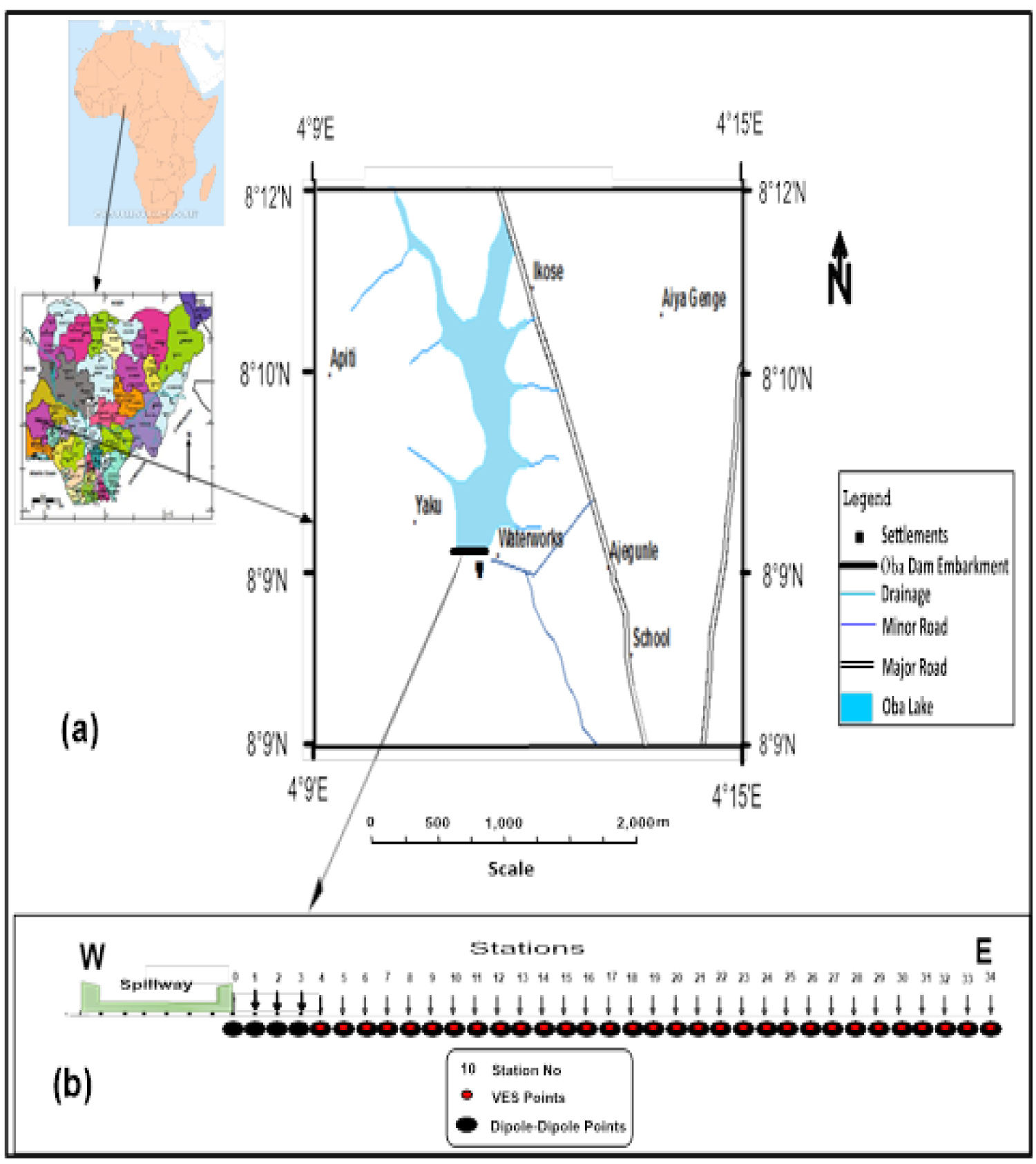
Figure 2: Base map of the study area showing...
Base map of the study area showing a) Oba lake and dam embankment; b) Geophysical traverse across oba dam embankment.


Figure 4: Typical sounding curves from the VES data...
Typical sounding curves from the VES data acquired along oba earth dam embankment a) KH-type; b) H-type; c) KH-type and; d) HA-type.
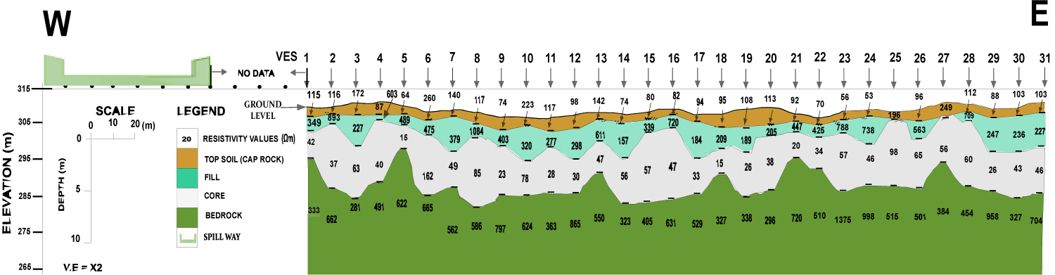
Figure 5: Geoelectric section along oba earth-fill...
Geoelectric section along oba earth-fill dam embankment.
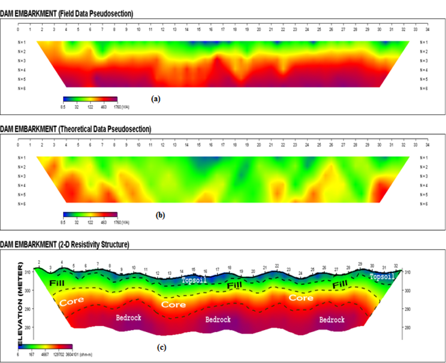
Figure 6: a) Field data pseudosection; b) Theoretical...
a) Field data pseudosection; b) Theoretical data pseudosection and; c) 2-D resistivity structure along dam embankment.
References
- Jackson S (2009) Seepage Monitoring in Embankment Dams. Doctoral Thesis, Royal Institute of Technology Stockholm, Sweden, 3.
- WCOSO (1997) Information on Ogbomoso Waterworks. Water Corporation of Oyo State, Ogbomoso Zonal Office. Ogbomoso.
- Olorunfemi MO, Ojo JS, Sonuga FA, Ajayi O, Oladapo MI (2000) Geophysical Investigation of Karkaru Earth Dam, Daura, Northeastern Nigeria. Global Journal of Pure and Applied Science 6: 117-124.
- Slimark S, Djordjevic N (1987) Dam Site Engineering Geophysics in Yugoslavia. First Break 5: 161-171.
- Butler DK, Llopis J, Deaver CM (1989) Comprehensive geophysical investigation of an existing dam foundation. Geophysics: The leading edge of exploration, Part 1. Geotechnical Application 5: 10-18.
- Aina A, Olorunfemi MO, Ojo JS (1995) An integration of aeromagnetic and electrical resistivity methods in dam site investigation. Bulletin of the International Association of Engineering Geology 51: 31-38.
- Olorunfemi MO, Ojo JS, Sonuga FA, Ajayi O, Oladapo MI (1999) Geoelectric and Electromagnetic Investigation of the failed Koza and Nassarawa Earth Dams around Katsina, Northern Nigeria. Journal of Mining and Geology 36: 51-65.
- Mainali G (2007) Monitoring of Tailings Dams with Geophysical Methods. Lulea University of Technology, Sweden.
- Abdel Aal GZ, Ismail AM, Anderson NL, Atekwana EA (2004) Geophysical investigation of seepage from an earth fill dam, Washington County, MO. Department of Geology and Geophysics, University of Missouri-Rolla MO. 65409.
- Batayneh AT, Al-zoubi AS, Abu-Ajamieh MM (2004) Geoelectrical soundings and their relationship to channel Seepage Areas at the Kaffrein Dam, Jordan. Journal of Applied Sciences 4: 28-37.
- Olorunfemi MO, Idornigie AI, Fagunloye HO, Ogun OA (2004) Assessment of anomalous seepage conditions in the opa dam, Ile-Ife, southwestern Nigeria. Global Journal of Geological Sciences 2: 191-198.
- Osazuwa IB, Chiichii E (2010) Two-dimensional electrical resistivity survey around the periphery of an artificial lake in the precambrian basement complex of northern Nigeria. International Journal of Physical Sciences 5: 238-245.
- Bayowa OG, Ilufoye DT, Animasaun AR (2011) Geoelectric investigation of awba earth dam embankment, University of Ibadan, Ibadan, Southwestern Nigeria, for anomalous seepages. Ife Journal of Science 13: 227-228.
- Gbadegesin A, Akinbola GE (1995) Reference Soil of the Southern Guinea Savanna of Southwestern Nigeria (Oyo State). Soil Brief Nigeria, 7, University of Ibadan and ISRIC, Wagningen, 13.
- Ogunfolakan A, Tubosun B, Aleru JO (2006) Archeological Survey of Igbo Oje near Ogbomoso, Oyo State, Nigeria, A Preliminary Report. NyameAkuma, 65: 47-55.
- Rahaman MA (1988) Recent Advances in the study of the basement complex of Nigeria. In: Oluyide PO, Mbonu WC, Ogezi AE, Egbuniwe IG, Ajibade AC, Precambrain geology of Nigeria. GSN, 11-41.
- Afolabi OA, Abimbola AF, Kolawole LL (2011) Preliminary study of the geology and structural trends of ogbomoso township, Southwestern Nigeria. Science Focus: An Internal Journal of Biological and Physical Sciences 2: 21.
- Koefeod O (1979) Geosounding Principles, 1. Resistivity Sounding Measurements. Elsevier Scientific Publishing Company, Amsterdam.
- Sjodahl P (2006) Resistivity investigation and monitoring for detection of internal erosion and anomalous seepage in embankment dams Engineering Geology. Lund University, 5-6.
Author Details
Bayowa OG*, Ogungbesan GO and Mudashir AW
Department of Earth Sciences, Ladoke Akintola University of Technology, Nigeria
Corresponding author
Bayowa OG, Department of Earth Sciences, Ladoke Akintola University of Technology, P.M.B. 4000, Ogbomoso, Nigeria, Tel: +2348030820291.
Accepted: October 22, 2019 | Published Online: October 24, 2019
Citation: Bayowa OG, Ogungbesan GO, Mudashir AW (2019) Geophysical Investigation of Oba Earth-Fill Dam Embankment using Electrical Resistivity Method. Int J Earth Sci Geophys 5:027
Copyright: © 2019 Bayowa OG, et al. This is an open-access article distributed under the terms of the Creative Commons Attribution License, which permits unrestricted use, distribution, and reproduction in any medium, provided the original author and source are credited.
Abstract
Continual post-construction checks on dam embankment are inevitable to forestall the possible catastrophes associated with its structural failure. In view of this, electrical resistivity (ER) surveys involving vertical electrical sounding (VES) and dipole-dipole profiling were conducted along the Oba dam embankment as a part of routine deformation monitoring for any possible seepage(s) around the dam embankment. Thirty-one vertical electrical soundings and thirty-five dipole-dipole horizontal profiling data were carried out on a 350 m long (west-east trending) traverse established along dam embankment. The iterated VES curves were mainly KH-type suggesting that Oba dam embankment is underlain by four geoelectric layers; topsoil (caprock), fill (granite materials), core (plastic-clay/wet clay) and basement bedrock with resistivity values range of between 53-249 Ωm, 205-1084 Ωm, 15-124 Ωm and 281-1375 Ωm, respectively. The dipole-dipole 2-D resistivity structure along the dam embankment showed no evidence of structural distress/weakness within the underlying sequences. Therefore, by integrating results obtained from geoelectric section and 2D resistivity structure based on the layer resistivity/lithological composition of the core materials (15-124 Ωm/plastic clay/clay/sandy clay), Oba earth-fill dam embankment integrity was good to very good indicating no seepage zone(s).
Keywords
Geophysical, Electrical resistivity, Oba rarth-fill dam, Embankment, Ogbomoso
Introduction
Dams are structures that prevent the flow of water and get it accumulated in a reservoir, river or stream, etc. Dams can be constructed from concrete, stones, masonry, loosed rock, earth wood, metal, or a combination of these materials. Hence, gravity, buttress and arch dams are possibly built. Earth-fill dams are examples of gravity dams which cosist of an impervious core made up of impermeable earth materials such as clay overlying impervious bedrock overlain by a less impervious caprock [1]. The Oba dam which is the focus of the present study is an example of an earth-fill dam.
Oba earth-fill dam was constructed in 1964 with a view to supplying the inhabitants of Ogbomoso and its environs potable water through a well-designed waterworks plants established close to the dam. The Oba reservoir (lake) derives its water content from river Oba in the area (Figure 1). The waterworks with expected life span of 50 years was designed to produce about 4.0 million litres per day. However, at present, the quantity of water being produced was about 2.8 million litres per day [2]. At present, Oba earth-fill dam is about fifty-five (55) years of age, hence, adequate attention is required to check the integrity of its embankment in order to prevent it from sudden collapse.
The catastrophes (loss of human and aquatic lives etc.) usually associated with dams’ failure are immense if the structure is breached or damaged. The integrity of a dam embankment can be undermined by the existence of geological features (e.g. faults, fractures, fissures, jointed or shear zones) precipitated seepage zones in the bedrock and/or discontinuities in the structure itself [3]. Earth dams in their natural state experience some degree of seepage and spillage flow from the reservoir and through permeable soils. Age of the dam, poor construction material; defect in the design can also responsible for dam collapse [3]. All the factors may cause the physical properties of the materials in the dam to change.
However, the electrical resistivity methods have the potential of detecting the physical state of such change. The use of electrical resistivity methods is gaining popularity among the geophysicists for post-construction deformation checks of seepage from drains in and around large dams is important to anticipate and permits remedial action to be taken before structural failure occurs. The methods are not only environmentally friendly and inexpensive but also timely [3-13]. As a result, the electrical resistivity survey involving the vertical electrical sounding (VES) using the Schlumberger array and 2-D electrical resistivity imaging using the dipole-dipole array was used along the crest of the of Oba earth dam, Ogbomoso Southwestern Nigeria to check the integrity.
Site Description
Oba Earth Dam is located in the northwestern part of Ogbomoso, Southwestern Nigeria within Latitude 8°9'N and 8°12'N and Longitude 4°9'E and 4°15'E (Figure 2). The dam is constructed within the channel of Oba River from which it sources its water. The dam embankment is 5m wide at its crest, 350 m long and 17 m high (Figure 3).
The study area is located within the tropical climatic zone that is characterized by two distinct seasons namely: The raining or wet and the dry seasons respectively. The wet season starts from around the months of March/April through to the month of October even though a little break in rainfall is usually experienced in the month of August. The month of November marks the beginning of the dry season which ends by the end of March. The temperature of the area is usually high throughout the year with an annual mean of 27 ℃. The relative humidity of the area varies from 60 to 80% [14]. The present vegetation of the site is the derived savannah with several baobab trees [15].
Ogbomoso falls within the Precambrian basement complex of southwestern Nigeria which comprises of migmatite-gneiss, banded-gneiss, porphyroblastic biotite-gneiss, granite and quartzite [16]. The porphyroblastic biotite-gneiss is spatially located at the northwestern end of Ogbomoso town towards Ikoyi where the rock is believed to underlie the Oba dam reservoir [17].
Methodology
A total of thirty-six geophysical stations at 10 m interval were established on a 350 m long, west-east trending traverse along the Oba dam embankment (Figure 2). All the stations were geo referenced using the Geographic Positioning System (GPS) for accurate positioning of the points. Thirty-one vertical electrical soundings (VES) were conducted on the established stations along the traverse with the Digital Direct Resistivity Meter (DDR3 Terrameter) using the Schlumberger electrode array, with the current electrode spacing (AB/2) having a maximum spread of 60 m. The obtained apparent resistivities (ρ) at each station were plotted against corresponding current electrode spacing (AB/2) on a log-log graph. while adopting partial curve matching technique [18] to generate initial layer earth model. The initial model was then iterated using IP2 win 1-D forward modelling software package to reduce the interpretation error to acceptable level. The final layer parameters (resistivities and thicknesses) were then used to prepare 2D geoelectric section across the dam embankment.
Thirty-six dipole-dipole profiling were also conducted on the established stations. Expansion factor n (i.e. distance between the leading and trailing potential electrodes) was varied from 1 to 6. The measured resistivity values are plotted against the points of intersection of two 45° inclined lines from the mid - points of the current and potential dipoles. The Dippro™ (version 4.01) software was used to produce 2-D resistivity structure beneath the dam embankment.
Results and Discussion
VES and geoelectric section along oba dam embankment
Typical iterated curves generated from the VES data are shown in Figure 4. The curve type includes the 3-layers H-type (6%) and 4-layers KH- (90%) and HA-types (3%). The geoelectric parameters and lithological description of the inferred geoelectric layers at each sounding point along the dam embankment are presented in Table 1. The geoelectric section (Figure 5) provides an insight into the geological sequence and structural disposition beneath the dam axis.
The geoelectric interpretation revealed that the area along the dam embankment is underlain by a maximum of 4 geoelectric layers (Table 1 and Figure 5). The topmost layer constitutes the topsoil and is made up of sandy clay/clay/clayey sand with layer resistivity ranging between 53 and 249 Ωm. The layer depth ranges between 0.6 and 1.8 m. The second layer is the fill (granite materials) having resistivity values that range between 205 and 1084 Ωm. The depth of the layer ranges between 1.2 and 2.7 m. The third layer has a resistivity value range of between 15 and 124 Ωm with depth range of between 2.5 and 9.1 m. This layer is presumably plastic-clay/clay/sandy clay. The fourth layer is suspected to be the basement bedrock. The resistivity values range between 281 and 1375 Ωm. Depth to rock head varied between 2.5 and 9.1 m.
2-D electrical resistivity structures
Figure 6 shows the field data pseudosection, theoretical data pseudosection and 2-D resistivity structures along the dam embankment. The 2-D resistivity structure represents the true picture of the geological structural disposition within the dam embankment. The image revealed a continuous blue colour band which indicates the topsoil (cap rock). The second layer (fill) is characterized by green colour band with resistivity values range from 35-1074 Ωm and layer thickness of between 4.2-11 m. The Third layer (yellow to light red) colour band is the presumed core. There is no any remarkable interface discontinuous observable in this layer. The fourth layer which is the basement bedrock is characterized by deep red colour bands. The resistivity values of the layer generally ranged between 57484-650628 Ωm.
Evaluation of the dam embankment integrity
Figure 3 shows the cross-section of the Oba earth dam embankment which is made up of a caprock/topsoil (low resistivity) overlying a resistive granite material (fill). The granite material overlies an impervious clay core sitting on high resistive competent bedrock. The characteristic geoelectric sounding curves across the embankment are the H, KH (about 90% of total type curves) and HA-type. The core material has resistivity values ranging from 15-124 Ωm typical of plastic clay/clay/sandy clay. However, plastic clay/clay constitutes 97% of the core material while the sandy clay constitutes 3% (Table 1). The 2-D resistivity structure shows no remarkable interface discontinuity among the subsurface sequences which could precipitate structural failure later on. The rating of the embankment integrity is based on layer resistivity/lithological composition as shown in Table 2 below. The Oba dam embankment integrity is good to very good with a pocket of fairly good at station 19 which is suspected to be a potential weak zone within the dam embankment [19].
Conclusions
The electrical resistivity method involving the dipole-dipole and VES data interpretation has been used to investigate the integrity of the Oba earth-fill embankment for possible structural distress within the dam embankment. The H, KH and HA-type curves constitute the characteristics sounding curves across the dam embankment. The geoelectric section and 2-D resistivity structure revealed four (4) distinct geoelectric subsurface sequences with no significant interface discontinuity within the dam embankment. The subsurface sequences delineated include the topsoil (caprock) which is presumably clay/sandy clay/clayey sand, the fill (granite materials), the core/weathered horizon made up of plastic clay/clay/sandy clay and the fourth layer suspected to be fresh basement bedrock. The plastic clay/clay constitutes 97% of the materials that constitute the dam embankment. The study concluded that Oba earth-fill dam integrity was good to very good based on the layer resistivity/lithological composition of the core materials obtained from the geoelectric section and the 2-D resistivity structure along the dam embankment.