International Journal of Experimental Spectroscopic Techniques
(ISSN: 2631-505X)
Volume 1, Issue 2
Review Article
DOI: 10.35840/2631-505X/8507

Article Formats
The Prism-Pair: Simple Dispersion Compensation and Spectral Shaping of Ultrashort Pulses
Table of Content
Figures
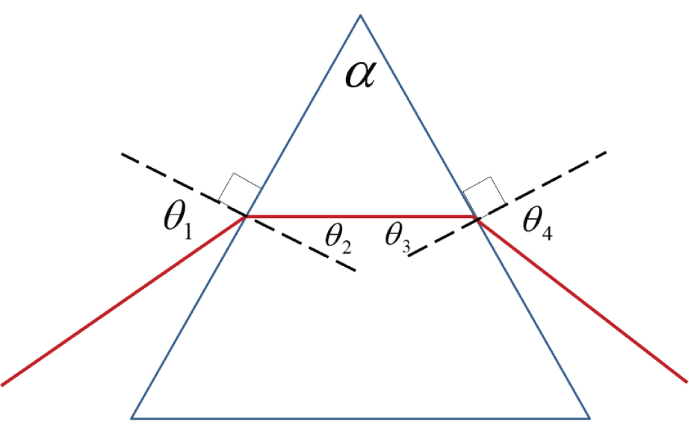
Figure 1: Symmetry relations between the refraction...
Symmetry relations between the refraction angles in a prism. At minimum deviation, the entrance and exit angles are equal and the ray propagates through the prism parallel to its base.
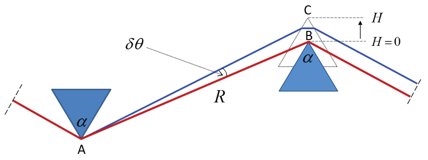
Figure 2: Geometry of a prism-pair, defined using two degrees...
Geometry of a prism-pair, defined using two degrees of freedom: the separation between the prisms R and the prism insertion H.
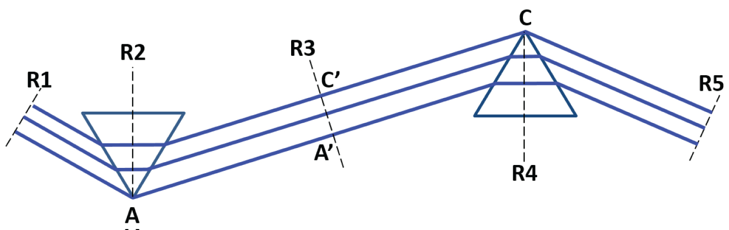
Figure 3: 15Different wavefronts (black dashed lines) of...
Different wavefronts (black dashed lines) of equal phase in a plane wave beam passing through a prism pair.
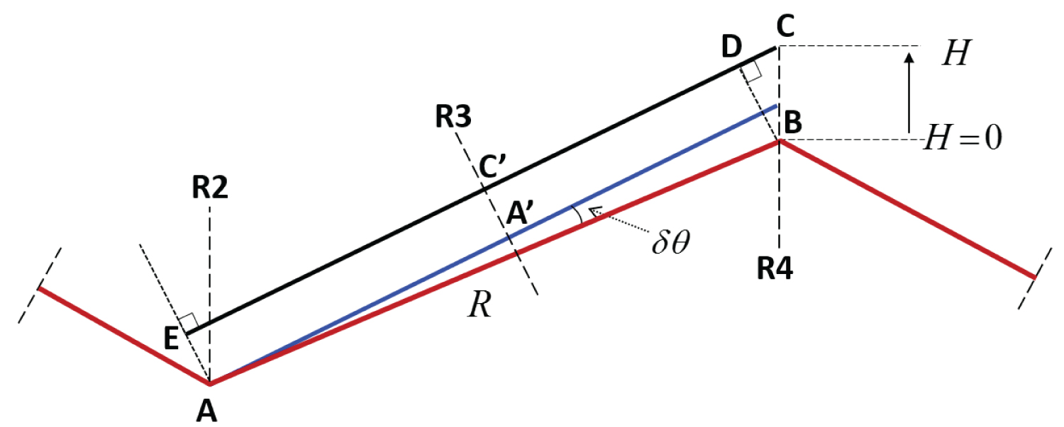
Figure 4: Complete optical path through a prism-pair...
Complete optical path through a prism-pair. Following a non-continuous ray by using the concept of wavefronts, the optical path through the entire system can be reduced to the segment EC.
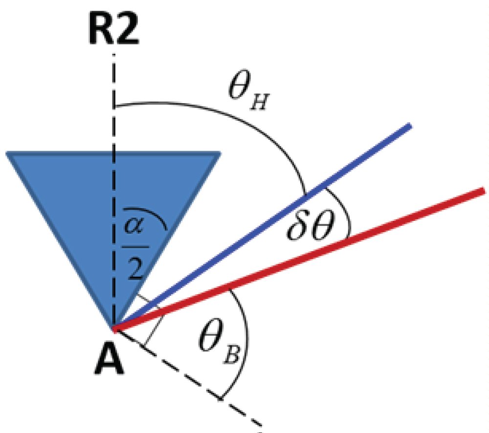
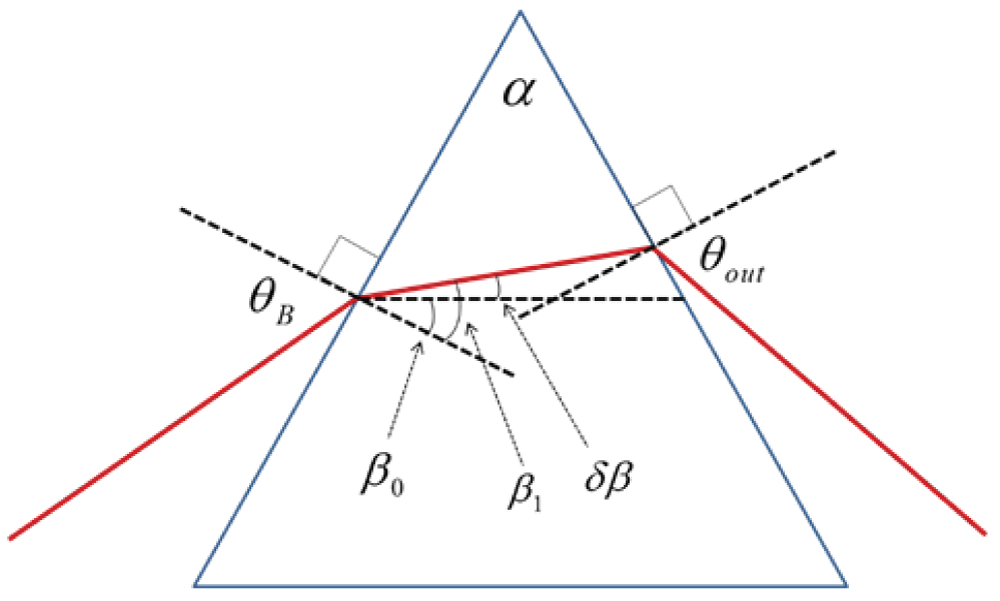
Figure 6: Definition of the refraction angles for...
Definition of the refraction angles for small angle approximation of the angular dispersion.
References
- Hargrove LE, R. Fork L, Pollack MA (1964) Locking of hene laser modes induced by synchronous intracavity modulation. Appl Phys Lett 5: 4-5.
- Spence DE, Kean PN, Sibbett W (1991) 60-fsec pulse generation from a self-mode-locked ti: sapphire laser. Opt Lett 16: 42-44.
- Zewail AH (2000) Femtochemistry: Atomic-scale dynamics of the chemical bond. J Phys Chem A 104: 56605694.
- Tannor DJ, Kosloff R, Rice SA (1986) Coherent pulse sequenceinduced control of selectivity of reactions: Exact quantum mechanicalcalculations. J chem phys 85: 5805-5820.
- Shapiro M, Brumer P (1996) Coherent control of collisional events: Bimolecular reactive scattering. Phys rev lett 77: 2574.
- Hansch TW (2006) Nobel lecture: passion for precision. Reviews of Modern Physics 78: 1297.
- Dhar L, Rogers JA, Nelson KA (1994) Time-resolved vibrational spectroscopy in the impulsive limit. Chem Rev 94: 157-193.
- Assion A, Baumert T, Bergt M, Brixner T, Kiefer B, et al. (1998) Control of chemical reactions by feedback optimized phase-shaped femtosecond laser pulses. Science 282: 919-922.
- Aharonovich I, Peer A (2016) Coherent amplification of ultrafast molecular dynamics in an optical oscillator. Phys rev lett 116: 073603.
- Weiner AM, Heritage JP, Kirschner EM (1988) High-resolution femtosecond pulse shaping. J Opt Soc Am B 5: 1563-1572.
- Dayan B, Peer A, Friesem AA, Silberberg Y (2005) Nonlinear interactions with an ultrahigh flux of broadband entangled photons. Phys rev lett 94: 043602.
- Weiner AM Ultrafast (2011) optical pulse shaping: A tutorial review. Opt Comm 284: 3669-3692.
- Weinacht T, Bartels R, Backus S, Bucksbaum P, Pearson B, et al. (2001) Coherent learning control of vibrational motion in room temperature molecular gases. Chem Phys Lett 344: 333-338.
- Oron D, Dudovich N, Yelin D, Silberberg Y (2002) Narrow-band coherent anti-stokes Raman signals from broad-band pulses. Phys Rev Lett 88: 063004.
- Vered RZ, Rosenbluh M, Pe'er A (2012) Two-photon correlation of broadband-amplified spontaneous four-wave mixing. Phys Rev A86: 043837.
- Gershgoren E, Bartels RA, Fourkas JT, Tobey R, Murnane MM, et al. (2003) Simplified setup for high-resolution spectroscopy that uses ultrashort pulses. Opt Lett 28: 361-363.
- Arissian L and Diels JC (2007) Carrier to envelope and dispersion control in a cavity with prism pairs. Phys Rev A75: 013814.
- Fork RL, Cruz CB, Becker P, Shank CV (1987) Compression of optical pulses to six femtoseconds by using cubic phase compensation. Opt lett 12: 483-485.
- Spence D, Sibbett W (1991) Femtosecond pulse generation by a dispersion-compensated, coupled-cavity, mode-locked ti: sapphire laser. JOSA B 8: 2053-2060.
- Ogilvie JP, Debarre D, Solinas X, Martin JL, Beaurepaire E, et al. (2006) Use of coherent control for selective two-photon fluorescence microscopy in live organisms. Optics express 14: 759-766.
- Entenberg D, Wyckoff J, Gligorijevic B, Roussos ET, Verkhusha VV, et al. (2011) Setup and use of a two laser multiphoton microscope for multichannel intravital fluorescence imaging. Nat protoc 6: 1500-1520.
- Kobayashi T, Yoshizawa M, Stamm U, Taiji M, Hasegawa M (1990) Relaxation dynamics of photo-excitations in polydiacetylenes and polythiophene. J Opt Soc Am B 7: 1558-1578.
- Shaked Y, Yefet S, Geller T, Peer A (2015) Octave-spanning spectral phase control for single-cycle bi-photons. New Journal of Physics 17: 073024.
- Shaked Y, Pomerantz R, Vered RZ, Pe'er A (2014). Observing the non-classical nature of ultra-broadband bi-photons at ultrafast speed. New Journal of Physics 16: 053012.
- Sensarn S, Yin GY, Harris SE (2010) Generation and compression of chirped bi-photons. Phys Rev Lett 104: 253602.
- Peer A, Silberberg Y, Dayan B, Friesem AA (2006) Design of a high power continuous source of broadband down-converted light. Phys Rev A 74: 053805.
- Bessire B, Bernhard C, Feurer T, Stefanov A (2014) Versatile shaper-assisted discretization of energy-time entangled photons. New Journal of Physics 16: 033017.
- Hecht E (1987) Optics (Addison Wesley).
- Yang S, Lee K, Xu Z, Zhang X, Xu X (2001) An accurate method to calculate the negative dispersion generated by prism pairs. Optics and Lasers in Engineering 36: 381-387.
- Arissian L, Diels JC (2007) Carrier to envelope and dispersion control in a cavity with prism pairs. Phys Rev A75: 013814.
- Fork RL, Martinez E, Gordon JP (1984) Negative dispersion using pairs of prisms. Opt Lett 9: 150-152.
- Cojocaru E (2003) Analytic expressions for the fourth- and the fifth-order dispersions of crossed prisms pairs. Appl Opt 42: 6910-6914.
Author Details
Yaakov Shaked1, Shai Yefet2 and Avi Pe'er1*
1Department of physics and BINA Center for Nano-technology, Bar-Ilan University, Ramat-Gan 52900, Israel
2Ophthalmology division, Lumenis LTD, Yokneam 2069204, Israel
Corresponding author
Avi Pe'er, Physics department and BINA center for nanotechnology, Bar Ilan University, Ramat Gan 52900, Israel, E-mail: avi.peer@biu.ac.il
Accepted: April 04, 2016 | Published Online: April 07, 2016
Citation: Shaked Y, Yefet S, Pe'er A (2016) The Prism-Pair: Simple Dispersion Compensation and Spectral Shaping of Ultrashort Pulses. Int J Exp Spectroscopic Tech 1:007.
Copyright: © 2016 Shaked Y, et al. This is an open-access article distributed under the terms of the Creative Commons Attribution License, which permits unrestricted use, distribution, and reproduction in any medium, provided the original author and source are credited.
Abstract
A simple and intuitive formulation is reviewed for the Brewster prism-pair - A most common component in spectroscopy-oriented experiments using ultrashort pulses. This review aims to provide students and beginners in the field of spectroscopy with a unified description of a major experimental component. The total spectral phase experienced by a broadband light field is calculated after passing through a pair of Brewster-cut prisms, demonstrating the flexibility of the prism pair to provide tuned, low-loss control of the dispersion and spectral phase experienced by ultrashort pulses.
Introduction
The generation of ultrashort pulses [1,2] revolutionized the field of molecular spectroscopy [3]. Not only that ultrashort pulses enable to observe molecular motion in time [4-6], but they allow also manipulation of the molecular dynamics [7-9] by controlling the spectral properties of the pulses. For this end, many types of pulse-shaping techniques and configurations are common in spectroscopy-oriented experiments. When complete control of the spectral amplitude and phase is required, a general Fourier-domain pulse-shaper [10] can be used, which provides independent control of both phase and amplitude for each frequency component of the light (e.g. with a spatial light modulator [11,12] or deformable mirrors [13]). However, most applications require only much simpler control of the group delay dispersion (GDD) and higher order dispersion to compensate for the dispersive effect experienced by an ultrashort pulse when passing through optical media and setups. For these applications, the high internal loss and technical complexity of a general pulse-shaper are a burden, and simpler configurations are commonly used, such as the grating-pair [14], chirped mirrors [15] or the Brewster prism-pair [16] - the subject of this mini-review. Prism-pairs can provide tuned compensation with ultra-low loss of up to two orders of dispersion (GDD and sometimes an additional higher order), along with simple amplitude control using a slit or transmission mask in the dispersive arm. Due to the low loss of the prism-pair, it is often the main 'tool of choice' for intra-cavity applications [17-19], low light level spectroscopy [20-22], and quantum optics experiments [23-27]. This mini-review presents a simple and intuitive formulation of the total wavelength-dependent phase accumulated by light passing through a prism-pair, and demonstrates how this major component is used for tuned, precise control of dispersion and spectral phase.
A Single Prism
The analysis starts by reviewing the geometry of a single prism. When a ray passes through a prism at minimum deviation, the angles of refraction through the prism are symmetric [28], as illustrated in figure 1, resulting in:
where α is the apex angle of the prism. If the entrance angle matches with the Brewster angle θB (for a certain wavelength λ0), the refraction angles obey
and the relation between the apex angle and Brewster angle can be expressed as
The Optical Path through a Prism-Pair
Our aim now is to calculate the total optical path (and phase) through a prism-pair, which will allow to derive the dispersion experienced by the passing optical pulse. The coordinate system used for the prism-pair has two degrees of freedom (Figure 2): R is the separation between the prisms (segment AB), and H is the penetration of the prism into the beam (segment BC). The red line represents a Brewster ray (at the design wavelength λ0) that enters and exits both prisms at Brewster angle θB. The blue line is the deviated ray at λ ≠ λ0, which deviates from the Brewster ray by an angle δθ due to the prism dispersion.
Wavefront Calculation
To calculate the phase accumulated by an arbitrary wavelength component λ (blue line) through the prism-pair, one usually calculates the optical path of the deviated beam along a continuous ray, starting from point A, through multiple refractions in the 2nd prism until a final reference plane perpendicular to the beam, located after the 2nd prism where all the colors are parallel [29,30]. This method results in somewhat complicated expressions for the optical path, leaving little room for intuition. An elegant alternative (outlined in Figure 3) that avoids calculations of multiple refractions is to use the concept of wavefronts for a non-continuous ray. This concept was originally presented in [31] and calculated to include only the prisms separation R. The following generalizes the calculation to include also the prism insertion H.
Each of the rays within a plane-wave beam experiences the same optical path (and phase) through the prism-pair, as illustrated in figure 3, starting from reference plane R1 to R5 (all the rays have the same wavelength λ0). Note that the optical phase is constant across each of the reference planes (dashed black lines), since each of them coincides with the wavefront perpendicular to the beam. The above argument is true not only for the Brewster ray λ0, but for any other wavelength λ. Since the wavefront R1 is common for all wavelengths, shifting its position only results in a simple optical delay, hence, the position of R1 can be chosen freely to pass through the point A. The same argument applies also to R5, which can be chosen to pass through point C.
Consequently, for calculating the geometric dispersion, it is sufficient if the optical path through the entire prism-pair is reduced to the segment:
Note that although this path is composed of free-space rays without refractions, it already takes into account refraction of the planar beam in the material. As illustrated in figure 4 (which shows the rays without the prisms for clarity), the optical path in Eq. 4 is identical to the segment EC, where the point C is the vertex of the 2nd prism. The conclusion is that the optical path of the deviated ray through the entire prism pair is simply given by:
where , and
Since EC is parallel to AA' and R2 is parallel to R4, one can see that is also the angle between R2 and the deviated ray (blue line) in the 1st prism, as illustrated in figure 5:
Substituting Eq. 3 into Eq. 6 obtains:
indicating that
By substituting the above relations into Eq. 5, the total optical path through the prism-pair is:
and the optical phase experienced by frequency ω is
Note that Eq. 8 was a generalization of the method presented in [31] in which only the special case of H = 0 is presented.
The expressions in equations [8] and [9] for the optical path P and optical phase φ are exact and can be easily used for numerical calculation of the spectral phase φ(ω) and its frequency derivatives , and higher order dispersion terms. The refraction angle δθ for each wavelength/frequency can be calculated according to Snell's law by using the prism's apex angle and the Sellmeier formula for either n(λ) or n(ω).
Approximation of the Prism Angular Dispersion
Although Eq. 8 and Eq. 9 already allow complete calculation of the dispersion properties, much intuition can be gained by further developing the expressions with the assumption that the angle δθ(λ) is small. Replacing and yields:
The angle can now be expressed using Snell's law assuming small angles, such that: and . It is assumed that the beam enters the 1st prism at the minimum deviation angle for a certain wavelength λ0; that the entrance angle matches the Brewster angle θB for λ0; and that the prism refractive index for λ0 is n(λ0) = n0. The refractive index for the deviated beam (λ ≠ λ0) is: .
The angle of refraction inside the prism for the Brewster beam is β0 (equal at both faces of the prism). As illustrated in figure 6, the angle of refraction for the deviated beam inside the prism is . It is easy to show that the deviated beam will hit the exit face of the prism at an angle of . The exit angle for the deviated beam will be . In addition, since at Brewster angle and , the following relations hold: and .
Following Snell's law from the entrance face to the exit, an approximation of the deviation angle δθ can be obtained. At the entrance:
Expanding the right hand side yields
Substituting into Eq. 11 and dividing by (and noting that ) provides
Following similar logic at the exit face of the prism, obtains
Expanding both sides of Eq. 14 yields
Equating both sides yields
Dividing Eq. 16 by provides
Substituting Eq. 13 into Eq. 17 yields
Finally, Eq. 18 can be substituted into Eq. 8 and Eq. 9 to retrieve the total wavelength dependent phase through the prism-pair. Since the wavelength/frequency dependence is now only in , a simple expression for the can be derived:
where and . The wavelength dependent refractive index of the prisms n can be obtained from the Sellmeier formula.
The exact spectral phase and any of its derivatives can be easily calculated using the chain rule [32]:
For typical optical bandwidths it is safe to assume that B ≫ 2Aδn and that R ≫ H, since and are common values. Thus, it is intuitive to think of A as the distance between the prisms (), and of B as the propagation distance inside the prisms. Further approximation can be made since for most practical optical materials 2.dn/dω ≪ ω.(d2n/dω2). Hence, the total GDD of the prism pair is the sum of two parts: the accumulated GDD from the material dispersion due to propagation through the prisms and an additional negative GDD resulting from the geometric dispersion from the path between the prisms:
The geometric dispersion in the second part attributes always a negative GDD for any material (independent of the sign of dn/dω), whereas the first part depends on the material dispersion, which may be either positive (as is usually the case in the visible or NIR range), or negative (as is usually the case for the IR in most materials). Hence, a simple prism-pair offers tunable GDD, both negative and positive, for visible and NIR wavelengths, but for the IR range it will commonly provide only negative GDD. Tuned positive dispersion in the IR range can still be obtained by inserting a 1x1_telescope between the prisms that can flip the sign of the geometric dispersion by imaging the first prism beyond the 2nd prism, effectively generating a "negative distance" R between the prisms [23].
Summary
The performance of the Brewster prism-pair was reviewed - a common major component of ultrafast spectroscopy apparati. The total spectral phase was calculated as accumulated by broadband light in passage through the prism-pair. Following a simple and intuitive approach using the concept of wavefronts, it was showed how the total optical path through a prism pair can be reduced to the path of a non-continuous beam, hence avoiding unnecessary computations of multiple refractions inside the prisms. Finally, the total phase and any of its derivatives can be easily calculated. Specifically, by careful choice of the two degrees of freedom of the prism pair R and H, it is possible to compensate two orders of dispersion simultaneously (e.g. d2φ/dω2 and d3φ/dω3), which is crucial when using ultra-broadband light to maintain high temporal resolution [23].