
International Journal of Magnetics and Electromagnetism
(ISSN: 2631-5068)
Volume 5, Issue 1
Research Article
DOI: 10.35840/2631-5068/6516

Article Formats
The Simulation and Optimization of the Magnetic Circuit for Magnetorheological Damper
Table of Content
Figures

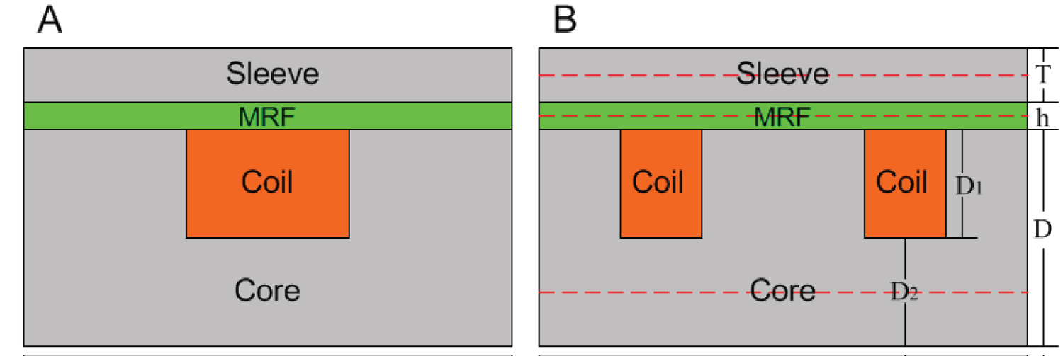
Figure 2: The schematic diagram of...
The schematic diagram of single-stage (A) and two-stage coil (B).
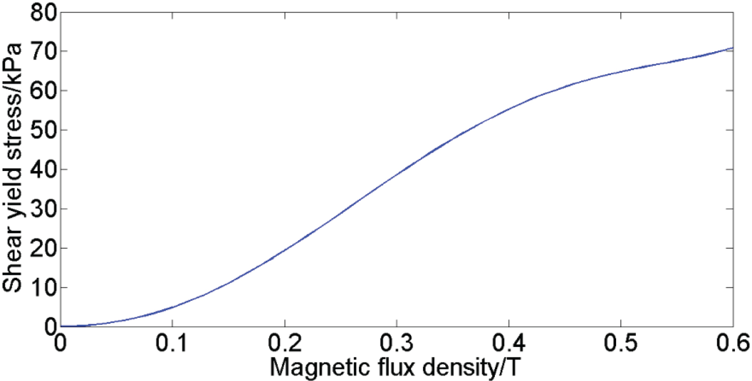
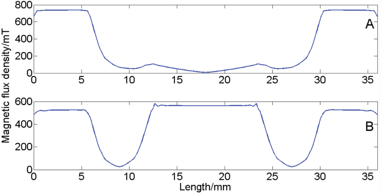
Figure 4: Magnetic flux density distribution of...
Magnetic flux density distribution of single-stage (A) and two-stage coil (B) design.
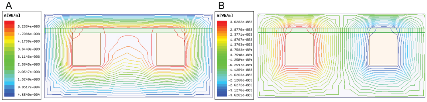
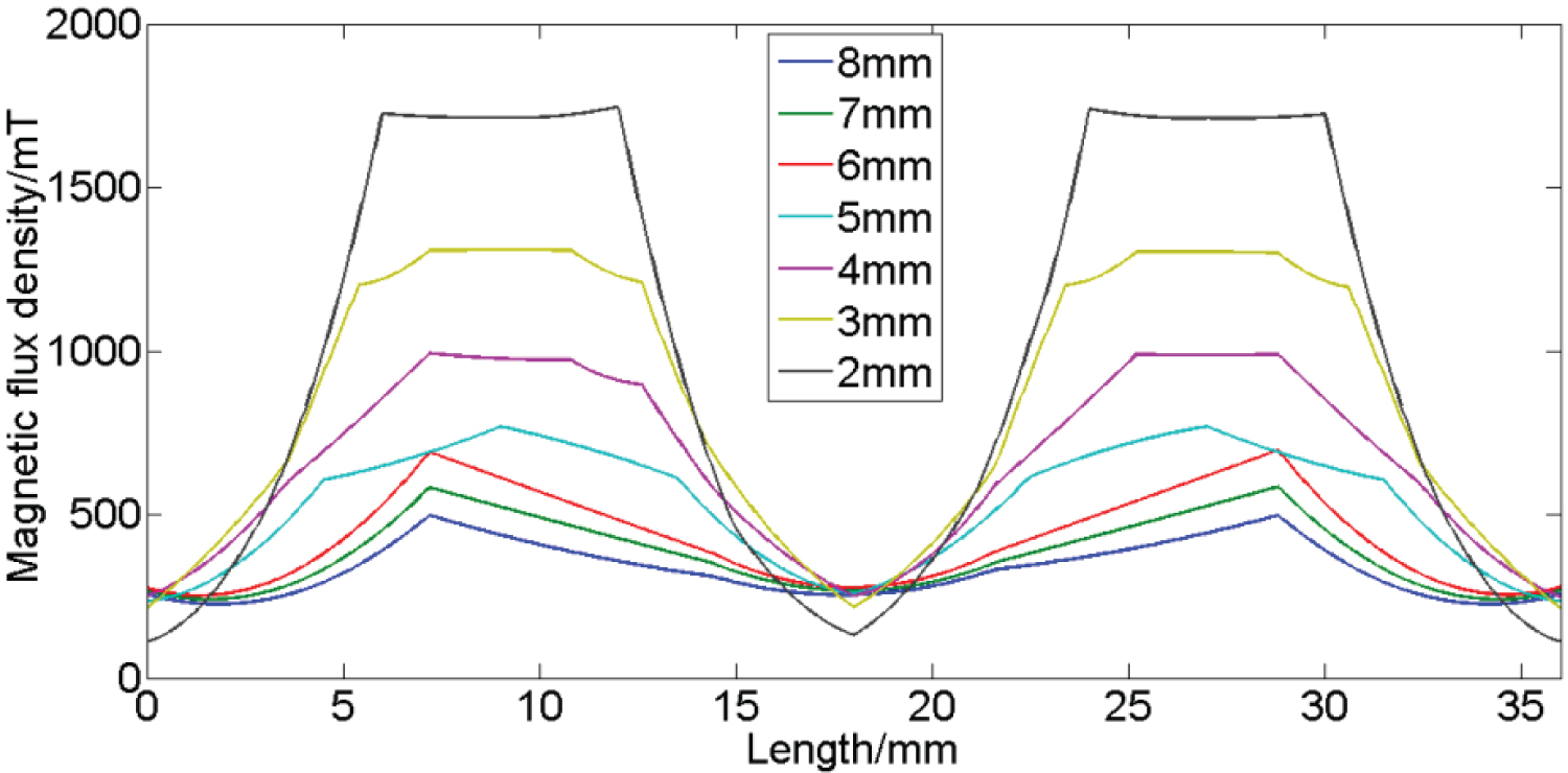
Figure 6: The magnetic field distribution...
The magnetic field distribution with different value of D2.
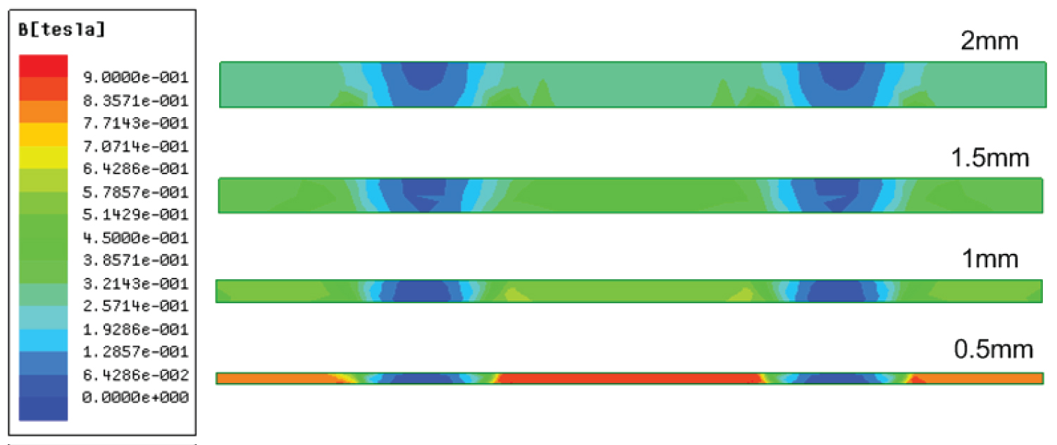
Figure 7: The cloud picture of magnetic flux density...
The cloud picture of magnetic flux density under different width.
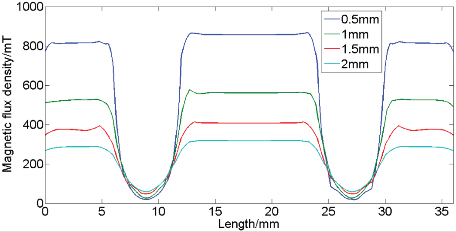
Figure 8: The relationship curve between...
The relationship curve between damping channel width and magnetic flux density.
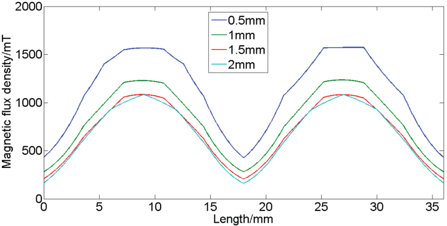
Figure 9: The magnetic field distribution...
The magnetic field distribution of sleeve with the variations of h.
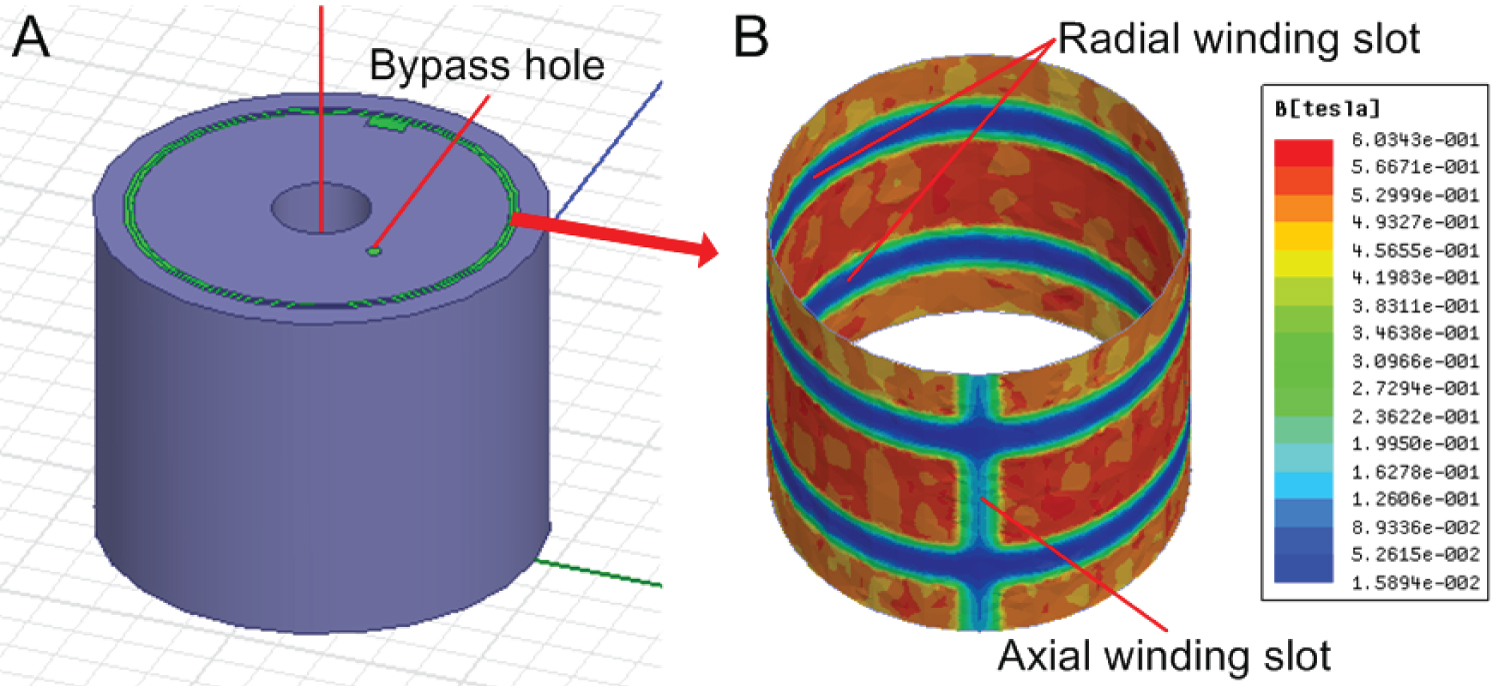
Figure 10: The 3D model of piston and its...
The 3D model of piston and its calculation result of magnetic field.
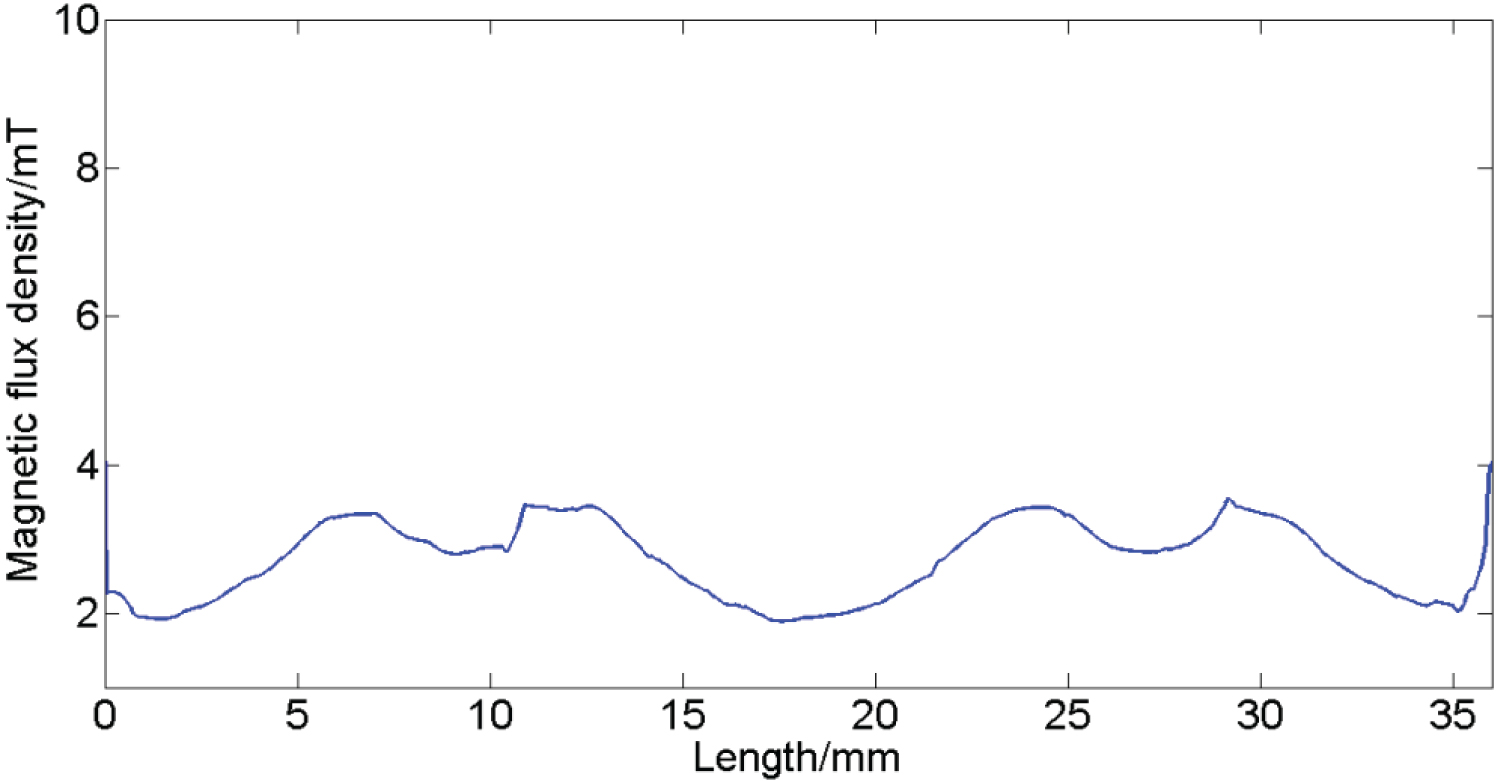
Figure 11: The magnetic field distribution...
The magnetic field distribution for the radial centerline of bypass hole.
References
- Dixon JC (2007) The shock absorber handbook. John Wiley and Sons, London.
- Karnopp DC, Crosby MJ, Harwood RA (1974) Vibration control using semi-active force generator. J Eng Ind 96: 619-626.
- Miller LR, Nobles CM (1988) The design and development of semi-active suspensions for a military tank. Society of Automotive Engineering Future Transportation Technology Conference and Exposition 881133.
- Poynor JC (2008) Innovative designs for magneto-rheological dampers. Virginia Polytechnic Institute and State University, MS Thesis.
- Stelzer GJ, Schulz M, Kim J, Randall J Allemang (2003) A magnetorheological semi-active isolator to reduce noise and vibration transmissibility in automobiles. J Intel Mat Syst Str 14: 743-765.
- Lau YK, Liao WH (2005) Design and analysis of magnetorheological dampers for train suspension. P I Mech Eng F-J Rai 219: 261-276.
- Hiemenz GJ, Hu W, Wereley NM (2008) Semi-active magnetorheological helicopter crew seat suspension for vibration isolation. J Aircraft 45: 945-953.
- Dong XM, Yu M, Li ZS, Liao CG, Chen WM (2009) A comparison of suitable control methods for full vehicle with four MR dampers part I formulation of control schemes and numerical simulation. J Intel Mat Syst Str 20: 771-786.
- Dong XM, Yu M, Li ZS (2009) A comparison of suitable control methods for full vehicle with four MR dampers part II controller synthesis and road test validation. J Intel Mat Syst Str 20: 1107-1119.
- Goncalves FD, Ahmadian M, Carlson JD (2011) Investigating the magnetorheological effect at high flow velocities. Smart Mater Struct 15: 75-85.
- Vicente J, Klingenberg DJ, Hidalgo AR (2011) Magnetorheological fluids: A review. Soft Matter 7: 3701-3710.
- Janusz G, Bogdan S (2012) Nondimensional characterization of flow-mode magnetorheological/electrorheological fluid dampers. J Intel Mat Syst Str 23: 1545-1562.
- Janusz G, Bogdan S (2013) Verification of magnetorheological shock absorber models with various piston configurations. J Intel Mat Syst Str 24: 1846-1864.
- Seong MS, Choi SB, Kim CH (2011) Design and performance evaluation of MR damper for integrated isolation mount. J Intel Mat Syst Str 22: 1729-1738.
- Ahmadian M, Ahn YK (1999) Performance analysis of magneto-rheological mounts. J Intel Mat Syst Str 10: 248-256.
- Farjoud A, Taylor R, Schumann E, Schlangen T (2014) Advanced semi-active engine and transmission mounts: Tools for modelling, analysis, design, and tuning. Vehicle Syst Dyn 52: 218-243.
- Bai XX (2013) Principle and key technologies of a self-powered/self-sensing Magneto-Rheological Damper. PhD thesis of Chongqing University, China.
- Yang G (2001) Large-scale magnetorheological fluid damper for vibration mitigation: Modeling, testing and control. PhD thesis of the university of Notre Dame, USA.
- Robert TF, Thomas WN, William CK, Oliver K (2012) Magnetorheological piston assembly with primary and secondary channels to improve MR damper force. USA.
Author Details
Benxiang Ju*
College of Mechanical Engineering, Chongqing University of Technology, China
Corresponding author
Benxiang Ju, College of Mechanical Engineering, Chongqing University of Technology, Chongqing 400054, China.
Accepted: January 22, 2019 | Published Online: January 24, 2019
Citation: Benxiang J (2019) The Simulation and Optimization of the Magnetic Circuit for Magnetorheological Damper. Int J Magnetics Electromagnetism 5:016.
Copyright: © 2019 Benxiang J. This is an open-access article distributed under the terms of the Creative Commons Attribution License, which permits unrestricted use, distribution, and reproduction in any medium, provided the original author and source are credited.
Abstract
Design and analysis of the magnetic circuit is an important step in design of magnetorheological (MR) damper. Magnetic Field-dependent damping force is affected by the construction of magnetic circuit and related parameters. In this paper, a kind of integrated piston assembly was presented and analyzed. The effect of several factors on performance of the magnetic circuit was calculated and studied, such as the different-stage coil, the same and opposite direction of coil, the width of damping channel, the diameter of core, bypass, and so on. Both 2D and 3D calculation were used to analyze and optimize the construction of magnetic circuit. The results demonstrate that these factors have different impact on magnetic circuit performance. It is expected that this work can hopefully be applied to guide the design of MR damper and related device.
Keywords
MR damper, Piston assembly, Magnetic circuit, MRF
Introduction
A vehicle damper is commonly known within the automotive industry as a shock absorber [1]. Vehicle dampers dissipate energy, whereas tires and springs absorb shocks in a suspension. Passive suspension systems using helical springs and viscous dampers are designed to meet the requirements of conflicting demands i.e., ride comfort versus road holding and handling. There is no possibility of changing the damper characteristics for different environmental conditions such as different road or weather conditions. Active or semi-active suspensions are one of the solutions used to improve the vehicle dynamic behavior and resolve the above-mentioned conflicting demands, and the semi-active damper's research started in the 1970s [2,3]. One of the most representative semi-active dampers is MR damper, and which is also one of the most effective and efficient vibration-control devices.
During the past two decades, a number of studies have been reported about the MR dampers. MRF is a kind of material, which is controlled by a magnetic field to allow the damping characteristics of the device to be continuously adjusted by varying the power of the electromagnet. MR dampers can offer an outstanding capability applicable in active/semi-active vibration control systems [4]. Stelzer has proved that the MR damper is more effective for vibration isolations than passive counterparts [5]. Currently, more and more MRF dampers have been developed and applied successfully in different vibration control systems, especially in vehicle suspension system [6-9]. To accommodate the fast-growing demand in MR dampers, different issues, including design, analysis, modeling, and control of MRF damper systems have been extensively studied [10-14]. However, In the MR damper, magnetic circuit plays a very important role in device overall characteristics due to magnetic circuit design affects both magnetic field and MRF flow. Among them, the MRF gap size is also an important part of the magnetic circuit, and it affects magnetic performance parameters such as flux density and time response of the mount [15,16].
Thus, to have a clear insight into the structure design of MRF damper systems, a comprehensive knowledge about various aspects of magnetic circuit design for MR damper is crucial. There are numerous tools that can be used for analyzing magnetic circuit, and these tools such as Ansoft Maxwell use finite element techniques to solve the problem of a magnetic circuit. This work discusses important aspects that need to be considered in magnetic circuit design such as 2D and 3D finite element calculation and analysis.
The Construction of Piston Assembly
The design of an MR damper is to ensure that it can sufficiently energize the MRF during the operation. The configuration of MR damper is shown in Figure 1A, mainly include cylinder, compensation assembly, seal and guide assembly, piston assembly and rod. The cylinder holds the compensation assembly that separates MRF from the high-pressure gas chamber. The damping properties of MR damper are mainly determined by piston assembly, and in order to further enhance the magnetic field in the MR damper, the entire magnetic circuit and guide structure are integrated in piston assembly. The detailed design of the piston assembly can be seen in Figure 1B.
In the design of the piston assembly, the different number of coils was considered to optimize the magnetic field. Single-stage and two-stage coil were analyzed, and the schematic diagram are shown in Figure 2.
In this work, the electromagnet design was done in detail by simulation analysis of 2D and 3D. MRF (MRJ-01, Chongqing Materials Research Institute) and electrical pure iron (DT4) are mainly materials for construction of the magnetic circuit. The piston sleeve and core are made of electrical pure iron. The model of these materials was established to simulate the magnetic circuit, the magnetic model of MRF and electrical pure iron can be expressed as follows [17], respectively.
The all relationship of magnetic flux density and magnetic field intensity was fitted by MATLAB. Where and are fitting coefficient, and the detailed value are , , , , , , , , , , , , , , , .
The magnetic field-dependent property of MRF was tested by using an advanced commercial rheometer (Model: MCR301), and the testing magnetic field of from 0 to 0.6 T was selected. Figure 3 shows relationship between the magnetic flux density and shear yield stress under different magnetic field, which display magnetic saturation of MRF occurs at about magnetic field of 600 mT, and this value plays a very important role for guidance of circuit design. In order to avoid magnetic saturation of MRF, the appropriate excitation magnetic flux density should be selected. Furthermore, the finite element method is widely used in electromagnet design and analysis for magnetic circuit. There are numerous analysis tools that can be used for this purpose. Ansoft Maxwell is one kind of analysis and calculation tools for using finite element techniques to solve the problem of a magnetic circuit. In this work, Ansoft Maxwell was used for finite element analysis of magnetic circuit.
2D Finite Element Analysis of the Magnetic Circuit
Comparison between single-stage and two-stage coil
Magneto-static finite element problems usually are quickly and have very good accuracy when correct material properties and boundary conditions are used. In this section, both designs based on different number of coils are studied and compared. Figure 4 shows the magnetic flux density distribution at the centerline (a dotted line is shown in Figure 2) of MRF.
Figure 4A and Figure 4B represent the calculation results of single-stage and two-stage coil design, respectively. The damping force is a key parameter for evaluating MR damper performance, and the damping force is expressed as [18]
Where represents the effective length of the damping channel, that's the critical portion of magnetic circuit, is viscosity without magnetic field, is the area of piston, is outer diameter of the piston, is the gap of damping channel, is running speed of piston, is the shear yield strength of MRF. Figure 4 implies that two-stage coil has more magnetic-controlled length in the gap for a certain level of excitation current. Thus, the two-stage coil has a higher performance than the single-stage coil under the same excitation conditions. Therefore, two-stage coil is a significant advance and will have promising applications in damping devices.
Comparison between same and opposite direction of two-stage coil
For MR damper, it is desired that the magnetic field excitation can be controlled for changing the damping force enough. So, the same and opposite direction of coil are also important for damping force generation. A plot of magnetic flux in piston at excitation current of 3A is shown in Figure 5.
As seen, the same winding direction for two-stage coil is shown in Figure 5A, while the opposite winding direction is shown in Figure 5B. The magnetic flux lines can be cancelled out each other at same winding direction, and that lead to hinder the magnetic field lines through the middle section of piston. As seen, magnetic flux lines form two loops at opposite winding direction. By contrast, the effective length () of the damping channel can be increased at opposite winding direction. That will be good for damping characteristics at opposite winding direction, and this can also be explained by using equation (3).
Influence of diameter of core on the magnetic circuit
The core of piston is most important part of the magnetic circuit. As illustrated in Figure 2B, the 2D model was built, and the reluctance maximum area of core was set to , and the can be expressed as . Where , represents the depth of coil slots. In this section, the excitation current was also set to 3A. The magnetic field distribution of (centerline) is shown in Figure 6.
Figure 6 reveals the magnetic flux density of (centerline) increases dramatically with the decreasing of . When a smaller value of is selected, the core has the possibility of reaching magnetic saturation, and the calculation result provides a good guidance to select the reasonable . In addition, to provide the required magneto-motive force with minimum reluctance, and a constraint is the total space available to accommodate the coil, the optimum of 7 mm was selected for this design.
Influence of damping channel width on the magnetic circuit
The design of a low reluctance magnetic circuit guides the magnetic field into a region where MRF needs to be energized. The damping channel width is an important parameter in the magnetic circuit, and the width was represented by in this paper. To study the influence of damping channel width on the magnetic circuit, the annular gap width was analyzed in the range of 0.5-2 mm and the excitation current of 3 A was applied to the MRF. Their width-dependent results are shown in Figure 7.
As can be seen from the Figure 7, four cloud picture exhibit similar performances, the magnetic flux density of MRF decrease steadily with increasing of the damping channel width, and this phenomenon can be more clearly expressed as Figure 8.
Figure 8 represents the magnetic flux density distribution at the centerline of damping channel, and a dotted line is shown in Figure 2. When damping channel width step was increased by 0.5 mm, the magnetic flux density has attenuated significantly. The magnetic flux density is as high as 850 mT when damping channel width is 0.5 mm under the excitation current of 3 A, while the damping channel width of 2 mm, the magnetic flux density of the centerline is only 300 mT. That indicates the damping channel width has a greater impact for the magnetic flux density of MRF. As can be observed from this result, a small damping channel width should be selected for piston design, and the magnetic saturation of MRF should also be considered at the same time.
The magnetic field distribution of the sleeve would be affected by variations of the damping channel width. The thickness () of sleeve was set to 3 mm in the design, and it may lead to magnetic saturation with the variations of . Using Ansoft Maxwell, the magnetic field distribution of sleeve was calculated with the variations of , and the result is described in Figure 9. As can be seen, the maximum magnetic flux density of sleeve was about 1200 mT when the optimum
3D Finite Element Analysis of the Magnetic Circuit
The detailed distribution of magnetic field can be analyzed more clearly using 3D finite element analysis. As seen Figure 10, 3D model (Figure 10A) of piston was established by using drawing tools, and the simulation results (Figure 10B) are computed at the excitation current of 3A.
In 3D model, an axial winding slot and two radial winding slots in outer body surface of the piston core, the axial winding slot extends from one side to another side of piston, and the radial winding slots include a first and second slot. In addition, a bypass hole is disposed inside the piston and in an axial, the bypass hole is typically linear and allows MRF to freely flow through the piston during MR damper operation. Robert has proved that the force performance of MR damper can be optimized by providing bypass hole [19]. The calculation results indicate the magnetic field distribution in the central region of MRF. Apart from the impact of the winding slot, the remaining area reached a magnetic field of 600 mT, and the magnetic field is distributed uniformly. The region of axial winding slot and two radial winding slots only occupy a very small surface area of piston core, and the magnetic field can reach 50~80 mT, that lead to little influence of filed-dependent forced performance. Present analysis verifies the applied magnetic field is appropriate to the operation of MR damper.
It is understood to one of ordinary skill in the art, that uses of the bypass hole is dependent on the force performance required in a particular MR damper application, and the magnetic field distribution based on the radial centerline of bypass hole is shown in Figure 11.
It can be seen from Figure 11 that the value of magnetic flux density is only about 2 ~ 4 mT. The bypass hole is mainly set for the liquid to flow freely, and it is affected by the magnetic field as small as possible. Combination with the result of Figure 3, this value can be ignored for impact on magnetic field-dependent force performance. MRF may be diverted into bypass hole which is substantially free of magnetic field effects. In a vehicle suspension system, this will provide "smooth" vehicle ride characteristics desired by a vehicle occupant.
Conclusions
The magnetic circuit was studied based on integrated piston assembly in this work. Both 2D and 3D finite element analysis was presented using Ansoft Maxwell and the optimization of magnetic circuit parameters was also discussed. The results show that the several factors on performance of the magnetic circuit, and different factors have different effect on the magnetic field distribution. Based on magnetic saturation of MRF at about magnetic field of 600 mT, the different-stage coil, the same and opposite direction coil, the damping channel width and the bypass hole have a greater impact on the performance of magnetic circuit. The Design and analysis methods discussed in this article assure satisfactory performance of an MR damper. It is expected that these procedure saves designer time and helps with optimizing magnetic circuit performance in a more systematic manner.
Acknowledgements
This work was supported by the Science and Technology Research Program of Chongqing Municipal Education Commission (No. KJ1709228), and the Startup Foundation of CQUT (NO. 2016ZD24).