International Journal of Optics and Photonic Engineering
(ISSN: 2631-5092)
Volume 4, Issue 1
Research Article
DOI: 10.35840/2631-5092/4517

Article Formats
Beam Shaping Optical Lens Designs for Diffraction-Free Bessel Beams
Table of Content
Figures
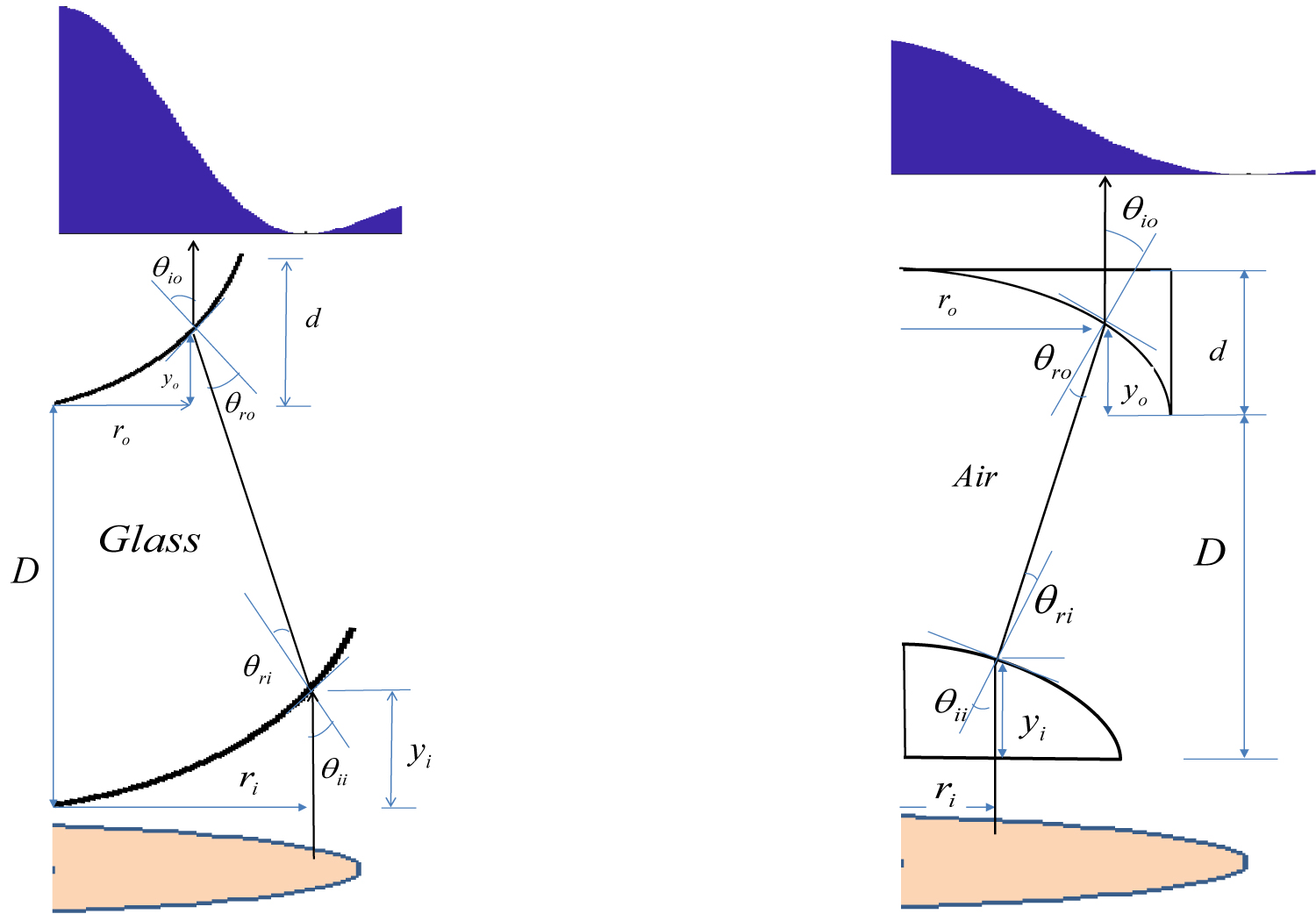
Figure 1: The geometric set-up of the refraction...
The geometric set-up of the refraction system beam transformation: a) One-element design and b) Two-element design.
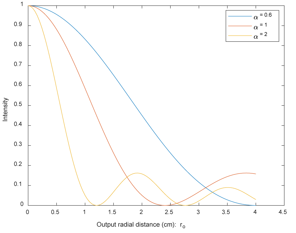
Figure 2: Intensity of zero-order Bessel...
Intensity of zero-order Bessel functions for different α.
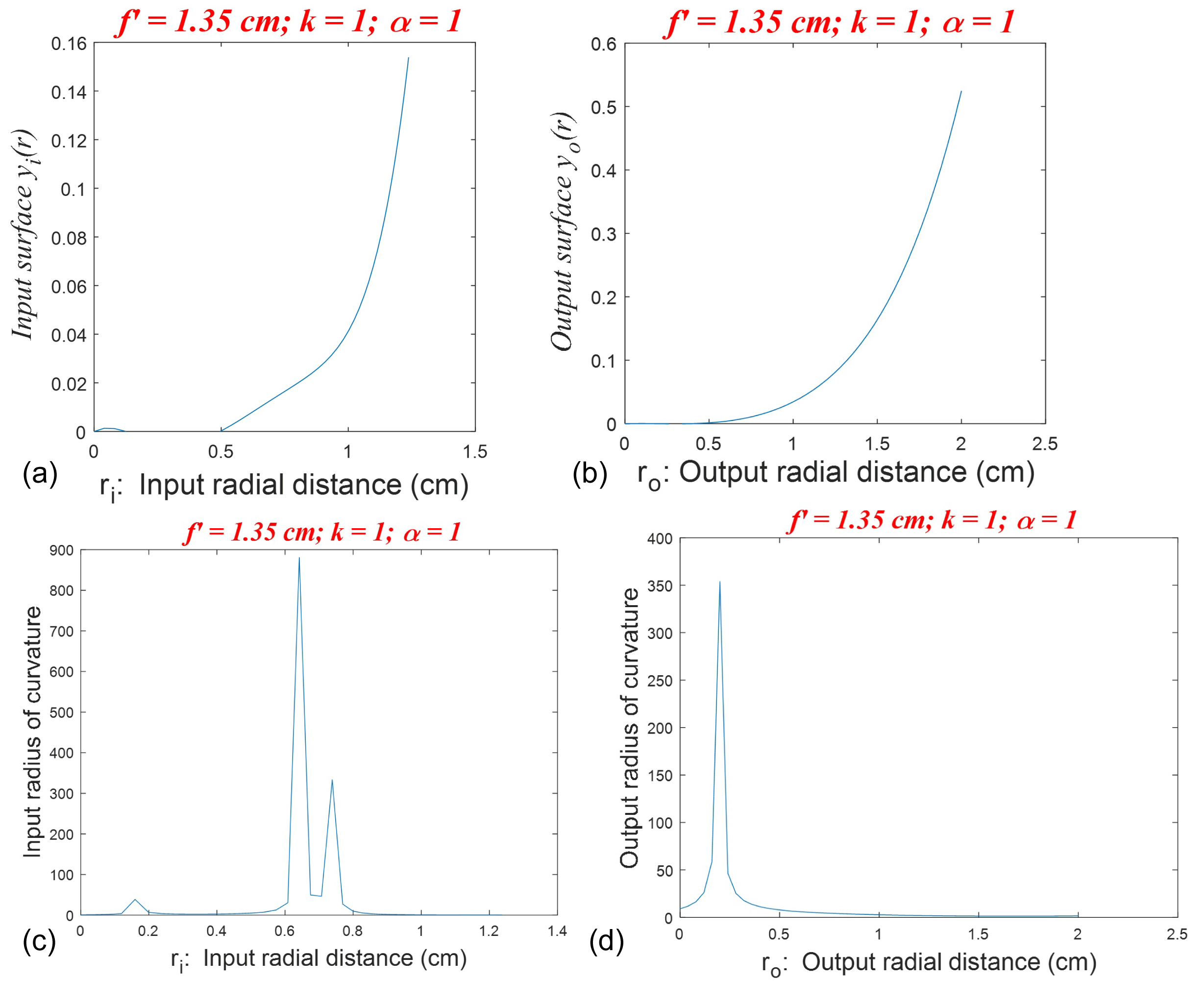
Figure 3: One-element design for uniform to Bessel...
One-element design for uniform to Bessel for f' = 1.35, D = 2.61, k = 1, α = 1: a) and b) The input and the output surfaces; c) and d) The input and the output radius of curvature of the surfaces.
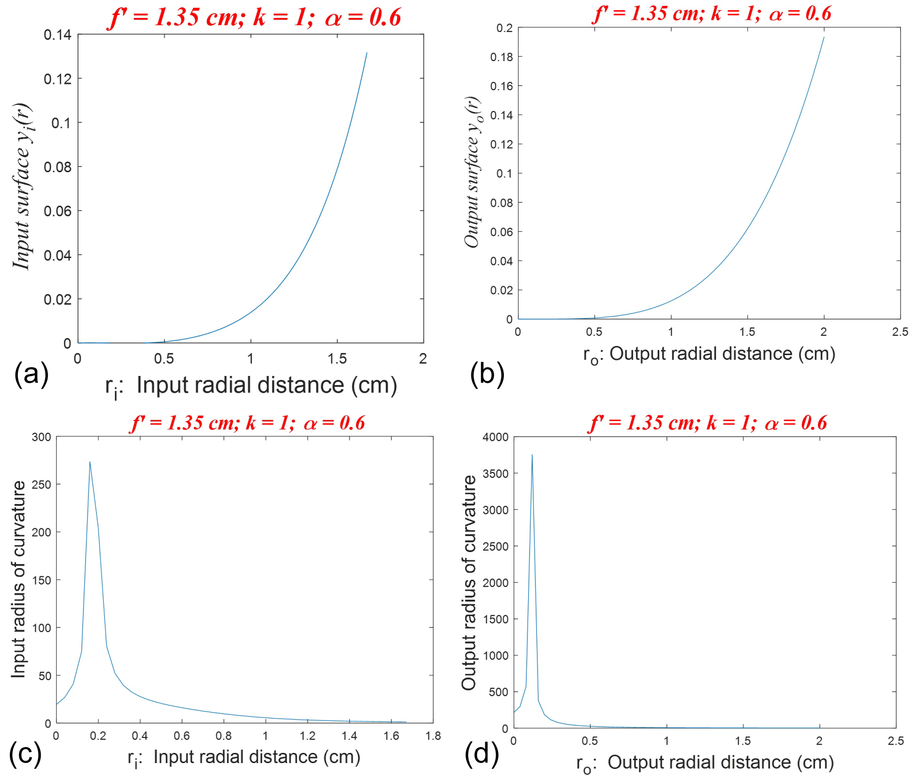
Figure 4: One-element design for uniform to Bessel for...
One-element design for uniform to Bessel for f' = 1.35, D = 2.61, k = 1, α = 0.6: a) and b) The input and the output surfaces; c) and d) The input and the output radius of curvature of the surfaces.
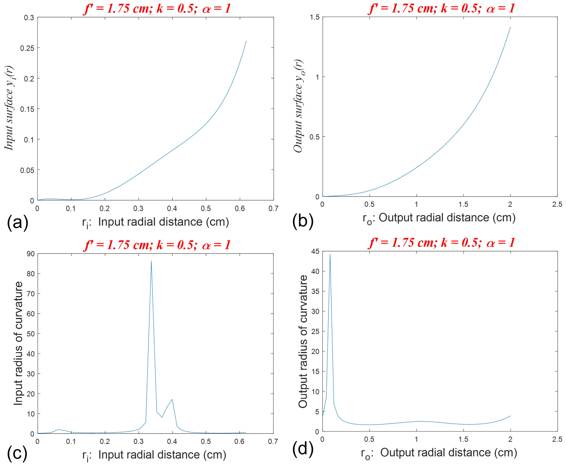
Figure 5: One-element design for uniform to...
One-element design for uniform to Bessel for f' = 1.35, D = 2.61, k = 0.6, α = 1: a) and b) The input and the output surfaces; c) and d) The input and the output radius of curvature of the surfaces.

Figure 6: One-element design for uniform to Bessel...
One-element design for uniform to Bessel for f' = 1.35, D = 2.61, k = 0.5, α = 0.6: a) and b) The input and the output surfaces; c) and d) The input and the output radius of curvature of the surfaces.
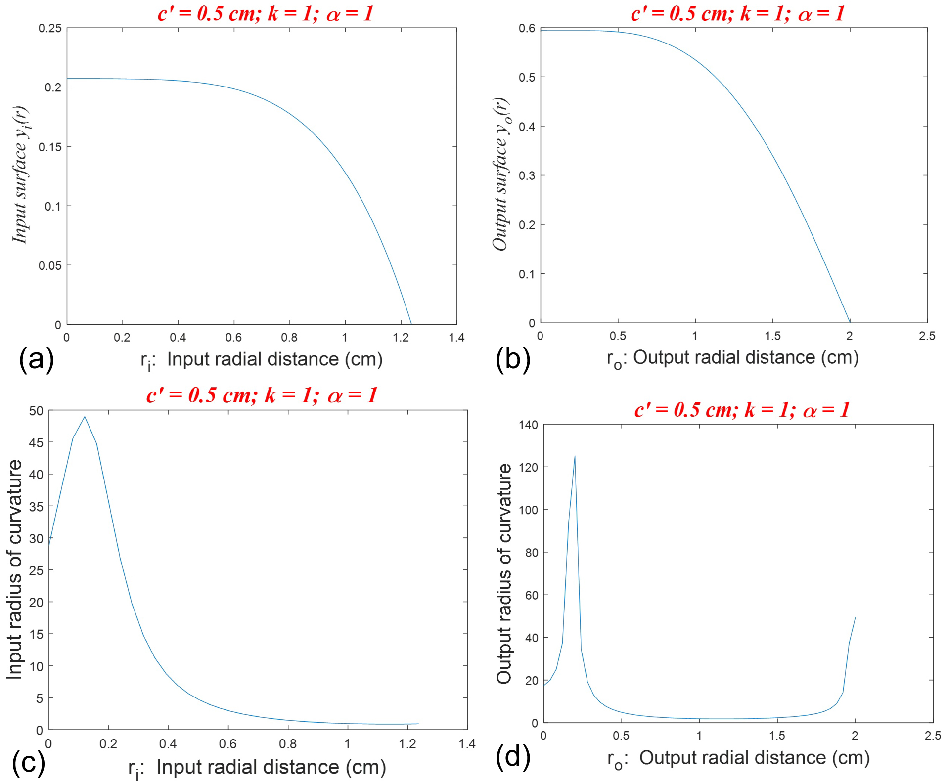
Figure 7: Two-element design for uniform to...
Two-element design for uniform to Bessel for c' = 0.5, D = 0.96, k = 1, α = 1: a) and b) The input and the output surfaces; c) and d) The input and the output radius of curvature of the surfaces.
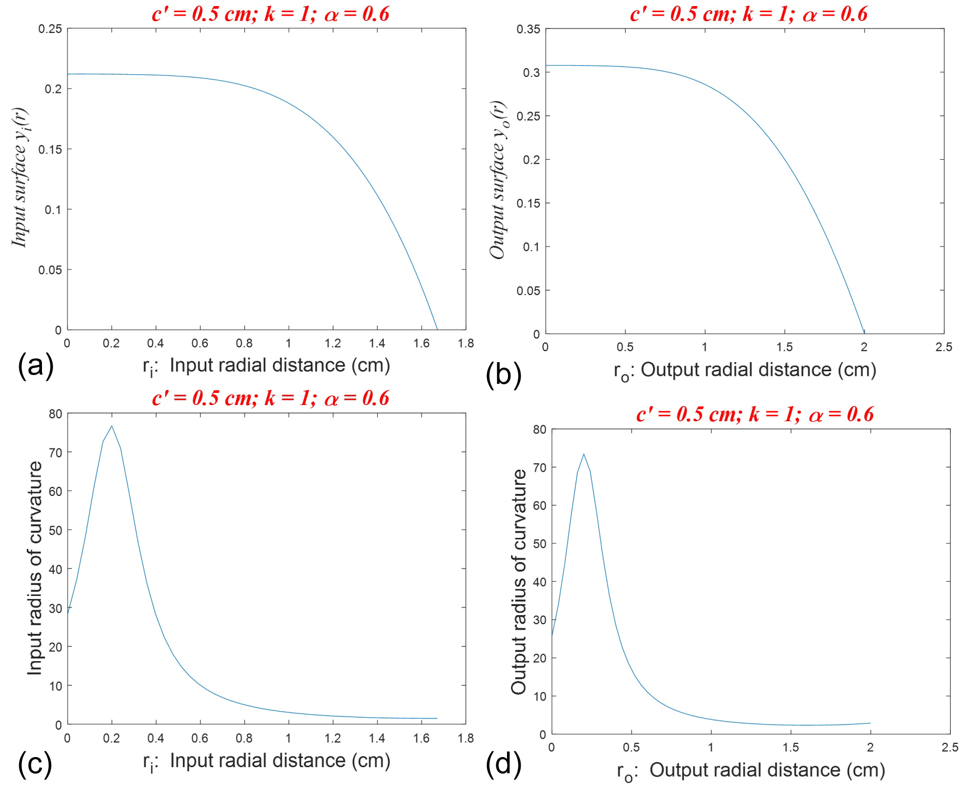
Figure 8: Two-element design for uniform to Bessel for...
Two-element design for uniform to Bessel for c' = 0.5, D = 0.96, k = 1, α = 0.6: a) and b) The input and the output surfaces; c) and d) The input and the output radius of curvature of the surfaces.

Figure 9: Two-element design for uniform to Bessel for c...
Two-element design for uniform to Bessel for c' = 0.5, D = 0.96, k = 0.5, α = 1: a) and b) The input and the output surfaces; c) and d) The input and the output radius of curvature of the surfaces.
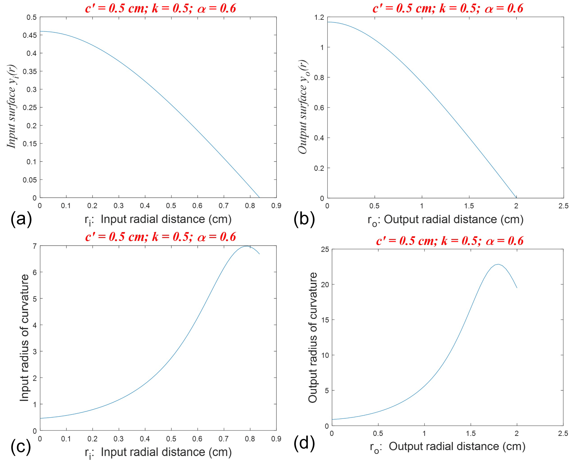
Figure 10: Two-element design for uniform to Bessel for c' = 0.5...
Two-element design for uniform to Bessel for c' = 0.5, D = 0.96, k = 0.5, α = 0.6: a) and b) The input and the output surfaces; c) and d) The input and the output radius of curvature of the surfaces.
References
- Ion JC (2005) Laser processing of engineering materials: Principles, procedure, and industrial application. Elsevier Butterworth-Heinemann, Burlington, USA.
- Narendra SPH, Dahotre B (2008) Laser fabrication and machining of materials. Springer, New York, USA.
- Duocastella M, Arnold CB (2012) Bessel and annular beams for materials processing. Laser Photonics Rev 6: 607-621.
- Kohno M, Matsuoka Y (2004) Microfabrication and drilling using diffraction-free pulsed laser beam generated with axicon lens. JSME International Journal Series B 47: 497-500.
- Courvoisier F, Lacourt PA, Jacquot M, Bhuyan MK, Furfaro L, et al. (2009) Surface nanoprocessing with nondiffracting femtosecond Bessel beams. Opt Lett 34: 3163-3166.
- Zambon V, McCarthy N, Piche M (2008) Fabrication of photonic devices directly written in glass using ultrafast Bessel beams. Proc SPIE 7079: 70992J.
- X Tsampoula, V Garcés-Chávez, M Comrie, DJ Stevenson, B Agate, et al. (2007) Femtosecond cellular transfection using a nondiffracting light beam. Appl Phys Lett 91: 053902-053904.
- Zhang G, Stoian R, Zhao W, Cheng G (2018) Femtosecond laser Bessel beam welding of transparent to non-transparent materials with large focal-position tolerant zone. Optics Express 26: 917-926.
- Durnin J (1987) Exact solutions for nondiffracting beams I: The scalar theory. J Opt Soc Am A 4: 651-654.
- Lu J-Y, Greenleaf JF (1992) Diffraction-limited beams and their applications for ultrasonic imaging and tissue characterization. In: FL Lizzi, New developments in ultrasonic transducers and transducer systems. Proc SPIE 1733: 92-119.
- Turunen T, Vasara A, Friberg AT (1988) Holographic generation of diffraction-free beams. Appl Opt 27: 3959-3962.
- Chattrapiban N, Rogers EA, Cofield D, Hill III WT, Roy R (2003) Generation of nondiffracting Bessel beams by use of a spatial light modulator. Opt Lett 28: 2183-2185.
- Kuntz KB, Braverman B, Youn SH, Lobino M, Pessina EM, et al. (2009) Spatial and temporal characterization of a Bessel beam produced using a conical mirror. Phys Rev A 79: 043802.
- Hwang C, Kim K, Lee B (2011) Bessel-like beam generation by superposing multiple Airy beams. Opt Express 19: 7356-7364.
- Chu X, Sun Q, Wang J, Lü P, Xie W, et al. (2015) Generating a Bessel-Gaussian beam for the application in optical engineering. Sci Rep 5.
- Paschotta R (2008) High-power lasers. In: The encyclopedia of laser physics and technology. (1st edn), Wiley-VCH.
- Dickey FM, Lizotte TE (2017) Laser beam shaping applications. (2nd edn), CRC Press publishing.
- Shealy DL, Chao S (2002) Geometric Optics-based design of laser beam shapers. Opt Eng 42: 3123-3138.
- Awwal AAS, Ahmed JU (2001) Refractive system for generation of high-power diffraction-free laser beams. Optics & Laser Technology 33: 97-102.
- Karim MA, Cherri AK, Awwal AAS, Basit A (1987) Refracting system for annular laser beam transformation. Appl Opt 26: 2446-2449.
- Thewes K, Karim MA, Awwal AAS (1991) Diffraction-free beam generation using refracting systems. Opt Laser Technol 23: 105-108.
- Arif M, Hossain NM, Awwal AAS, Islam MN (1998) Two-element refracting system for annular Gaussian-to-Bessel beam transformation. Appl Opt 37: 4206-4269.
- Arif M, Hossain MN, Awwal AAS, Islam MN (1998) Refracting system for annular Gaussian-to-Bessel beam transformation. Appl Opt 37: 649-652.
- Cherri AK, Khachab NI, Habib MA (2017) Two-element refracting system for Gaussian and annular-Gaussian beams transformation. International Journal of Photonics and Optical Technology 3: 5-10.
- Cherri AK, Khachab NI, Habib MA (2017) Designs of Two-element optical refracting system to achieve uniform laser beam profile. Journal of Applied Mathematics and Physics 5: 2371-2385.
Author Details
Abdallah K Cherri* and Mahmoud K Habib
Electrical Engineering Department, College of Engineering and Petroleum, Kuwait University, Kuwait
Corresponding author
Abdallah K Cherri, Electrical Engineering Department, College of Engineering and Petroleum, Kuwait University, P. O. Box 5969, Safat 13060, Kuwait, Tel: +965-2498-7376.
Accepted: May 27, 2019 | Published Online: May 29, 2019
Citation: Cherri AK, Habib MK (2019) Beam Shaping Optical Lens Designs for Diffraction-Free Bessel Beams. Int J Opt Photonic Eng 4:017.
Copyright: © 2019 Cherri AK, et al. This is an open-access article distributed under the terms of the Creative Commons Attribution License, which permits unrestricted use, distribution, and reproduction in any medium, provided the original author and source are credited.
Abstract
Beam shaping technique is applied to design optical lenses for transforming uniform beams to diffraction-free Bessel Beams. One-lens and two-lens refracting system will be demonstrated where the lens' surfaces equations can be easily derived. The designed lenses take the input uniform beam distribution and confine it to be within the main lobe of the Bessel beam and avoid its zeros crossings. Various design parameters such as the power of the beam and the optical system length will be discussed. It will be demonstrated that the two-element design will produce smaller system length than the one-element design.
Keywords
Beam shaping methods, One-element and two-element refracting system, Lens design
Introduction
The fundamental mode (TEM00) of the cavity of Gaussian laser beam is the most common beam shape used in optical processing. In particular, for materials processing [1-8] the low divergence of the Gaussian beam provides a small focused spot. It can be shown that a focal spot size as small as 1 μm can be obtained using a lens with a given numerical aperture NA [3]. The small spot size is very attractive for microfabrication applications. Further, for laser materials processing, the depth of field (DOF) or the distance (from the beam waist over which the focal beam size and the peak intensity keep their values) is very important factor. The DOF of Gaussian beam is too short for many industrially important processing applications [1] due to transverse spreading. As the use of laser in materials processing increases, researchers increase their efforts in exploring other non-Gaussian laser beams (due to its short, micron-sized Rayleigh range), such as the non-diffracting Bessel beams [9], which have an accurate laser beam focusing over a good distance range. This comes at the expense of reducing the amount of energy available in the process where Gaussian beam has an advantage over any other beam shape.
Bessel beams, in contrast to Gaussian beams, have extended DOF with a minimal spreading in the central lobe during wave propagation. This non-diffracting property attracts researchers to attempt using Bessel beams in many new applications. The researchers' efforts appear, recently, in much usage of micro and femtosecond lasers to process a broad variety of materials such as metals, glass, semiconductors, biological samples, etc with very high degree of precision and reproducibility, and with minimized laser induced damage. Bessel beams can be generated by many methods [10-15]. Lasers with high output powers are required for a number of applications, such as for material processing (welding, cutting, drilling, soldering, marking, surface modification) [7,16], where many of these beams are generated in unstable resonator. For instance, using a ring-type reflective mirror inside the resonator results in an output annular beam profile.
On the other hand, beam shaping techniques were proposed to convert laser beam profiles to other beams profiles [17,18]. Refractive optical system technique is among many successful and efficient methods that can achieve this conversion. This technique relies on geometric optics for designing laser beam shapers. The designed optical element functions as a field mapping of the input beam distribution to provide a desired output beam profile. In the past one-element and two-element refracting systems were reported to transform annular-Gaussian to Bessel beam [19-23]. Recently, we have proposed the design of such refractive systems for generating various other laser beams profiles [24,25] such as:
(i) Annular-uniform-to-uniform;
(ii) Annular-Gaussian-to-uniform;
(iii) Gaussian-to-uniform;
(iv) Gaussian to Annular-uniform;
(v) Annular-Gaussian to Annular-uniform;
(vi) Annular-Gaussian to Gaussian;
In this paper, we further extend the previous works to design refractive systems to transform uniform circular beam to diffraction-free circular Bessel beams using one-element and two-element lenses. A procedure to derive the mathematical expressions of the input and output lens surfaces is provided for beams transformations from uniform to Bessel. The designed lenses take the input beam distribution and confine it to be within the main lobe of the Bessel beam and avoid its zeros crossings. It will be shown that for a given system specified with certain dimensions and power concentration, then the design parameters can be changed to meet these specifications. Further, the designed surfaces of the lenses are smooth enough to be fabricated. It will be demonstrated that the two-element design will produce smaller system length than the one-element design.
Design Considerations
Figure 1a and Figure 1b show schematics of half of the proposed axially symmetric refracting system for uniform to Bessel beam transformation for one-element and two-element, respectively. The lens is made from glass with index of refraction n = 1.5172. D is the distance between the input and the output horizontal reference planes. Starting with an incident ray that hits the first surface of the lens with an angle θii, it will be refracted by an angle θri. The refracted ray reaches the second lens surface with an angle θro and then it is refracted by an angle θio. Note the parallelism between the incident and the exited ray. The lens surfaces are represented by yi(ri) and yo(ro) functions of the radial distances ri and ro of the input and output surfaces, respectively.
Beam shaping method design imposes few conditions that must be met to realize beam conversion such as: a) All input rays that enter and leave the lens must travel the same optical path length; b) All input rays that enter and leave the lens must be parallel to each other's; and c) The ratio of the input beam power to the output beam power must equal to a constant.
For the one-element design, the first two design conditions are translated into the following equations:
Where f is a constant and f' = f - d - D. Further, the input and the output rays parallelism dictates that both the input and the output surfaces slope must be equal to each other, i.e.
Furthermore, using Snell's law at the input lens (sinθii = nsinθri) along with trigonometric identities, one can obtain:
And
Note that Eq. (5) imposes a minimum value on the length f' to avoid the singularity. On the other hand, similarly, for the two-element design, we can obtain the following equations:
Where c is a constant and c' = c - nd - D.
Laser Beam Transformations
The first step in the procedure for designing the refracting lens starts with establishing a relationship between ri and ro the radial distances of the lenses' surfaces. The above-mentioned third condition of beam shaping can be used in this regard. This condition is translated into a relationship between the cross-sectional areas of the uniform and the Bessel beams:
Where J0 is the zero-order Bessel function of first kind, ri is the radius of the input circular beam, ro is the radius of the output Bessel beam, k is a constant that defines the amplitude, and α is a parameter that sets the width or diameter of the main lobe of the Bessel beam as shown in Figure 2. The diameter of the central lobe is a main parameter that may control the Rayleigh range [3] for Bessel beam and the power in the central lobe. Eq. (10) leads to the following relationship:
Eq. (11) expresses the relationship between four parameters in the lens design, i.e., ri, ro, k, and α. The parameter α sets the first zeros in the Bessel beams that are approximately 4, 2.4, and 1.2 for α = 0.6, 1, and 2, respectively. The designer may select a specific beam spot size ro for a particular beam and obtain the size of the input beam ri. For instance, for Bessel beam with α = 0.6, the input power will be delivered to a spot size of ro = 2 (50% of central lob width). Thus, for α = 0.6, ro = 2 and for a selected value for k (say k = 1), we can easily determine the required value of the input beam ri = 1.68 and the minimum value of f' = 0.37. Similarly, for 95% of the central lobe (ro = 3.8), ri is found to be 2.08.
On the other hand, Eq. (11) shows that k has effects on the value of ri. At the same time, the value of f' in Eq. (4) depends on ri. Further, Eq. (5) depends on both f' and ri. As a result, varying k will eventually vary the minimum value of the length of the system and the lens input and output surfaces. For example, for α = 0.6, ro = 2, k = 0.5; then ri = 0.84 and the minimum value of f' = 1.33.
The second step in the beam shaping design procedure is to specify a value of the system length (f', c', or D), which determine the numerical values for the surfaces slope dyi/dri and dyo/dro from Eqs. (5) and (9). The third step in the design procedure is to use a curve-fitting routine to determine mathematical expressions for these slopes from their numerical values. Finally, by integrating the mathematical expressions of these slopes, we can obtain the mathematical expressions of the surfaces yi(ri) and yo(ro). Note that in the design procedure, selecting design parameters should take into consideration that the system length to be as small as possible and the radii of curvature, for the lens surfaces to be large. In the following subsections, we will present designs for one- and two-element system for different parameters values of k, α, and (f' or c'). These parameters will change the shape of the lens and the size of the designed system.
One-element designs
For the one-element design, we will present four designs to demonstrate the effects of parameters k and α. For the first two designs, we choose f' = 1.35 cm (D = 2.61), k = 1, ro = 2 (50% of central lob width), for α = 1 and α = 0.6, as shown in Figure 3 and Figure 4. In these figures, when α decreases, then the input radial distance ri increases from ri = 1.24 to ri = 1.68. Further, for α = 1, it is found that the minimum value for f' is 0.87 which corresponds to a minimum length distance D = 1.68 cm; while for α = 0.6, the minimum value for f' is 0.37 which corresponds to a minimum length distance D = 0.71 cm.
Next, for the second two designs, we selected f' = 1.75 cm (D = 3.384), k = 0.5, ro = 2 (50% of central lob width), for α = 1 and α = 0.6, as shown in Figure 5 and Figure 6. Note that when k decreases by a factor of 2, then ri decreases by the same factor. However, the minimum values for f' are changed to 1.58 (D = 3.01 cm) and 1.33 (D = 2.57 cm), for α = 1 and 0.6, respectively. This may explain why f' = 1.75 cm was selected in our design. Table 1 summarizes these results and includes others the designs parameters such as for α = 1 and k = 2 for both 50% and 95% central lobe widths.
As an illustration of the derivation of the mathematical expressions of the lens surfaces yi(ri) and yo(ro), we present the derivation of the design of Figure 3. We choose f' = 1.35 cm, k = 1, ro = 2, α = 1. Substituting f' in EQ. (7) and using both (3) and (11), we can obtain the numerical values for the surface slopes and . The mathematical expressions for these slopes are achieved using a polynomial curve-fitting routine to yield:
Integrating the above expressions to provide approximate equations for the lens' surfaces as:
Two-element design
Similarly, for the two-element design, Figure 7, Figure 8, Figure 9 and Figure 10 illustrate the four designs to demonstrate the effect of parameters k and α. Note that, in contrary to Eq. (5), Eq. (9) does not suffer from any singularity for the chosen glass with n = 1.57.
For the first two designs, we have chosen the same design parameters as for the one-element design, i.e., k = 1, ro = 2 (50% of central lob width), for α = 1 (ri = 1.24) and α = 0.6 (ri = 1.68). However, we have selected a much smaller system length c' = 0.5 cm (D = 0.96 cm) compared to D = 2.61 cm. These designs are shown in Figure 7 and Figure 8. In these figures, when α decreases, then the input radial distance ri increases for a fixed k.
Next, to demonstrate the effect of k on the design, we have reduced k to 0.5 and kept the same parameters as the previous two designs. These designs are shown in Figure 9 and Figure 10. Since there is no singularity issue in Eq. (9), then we can still use the same value of c' = 0.5 cm (D = 0.96). The effect of k is restricted to only changing the value of ri. Again, the two-element design achieved smaller system length than the one-element one. However, accurate alignment and precise separation between the two lenses are essential to achieve the desired output profile.
Conclusion
One- and two-element lens designs for transforming laser beam profiles are considered in this work using optical refracting system. The lens-design is applied to transform circular-uniform beam to be focused on the central beam lobe of a Bessel beam profile. In laser material processing, extending the DOF is very important. The minimal spreading of the central lobe of the Bessel beam during wave propagation makes extending the DOF possible. A procedure for obtaining the mathematical expressions for the two aspheric surfaces is outlined. An example was provided to illustrate the procedure. In addition, few important parameters such as the length of the system, the power ratio of the beams, and the first zero crossing of the Bessel function, are discussed. The radii of curvature of the designed surfaces are high. This leads to smooth and gradual change on the surfaces for relative ease for machining and fabrication. It can be concluded that the two-element design will produce smaller system length than the one-element design.