
International Journal of Optic and Photonic Engineering
(ISSN: 2631-5092)
Volume 6, Issue 1
Research Article
DOI: 10.35840/2631-5092/4533

Article Formats
Increase in Optical Transmittance of Polyethylene Terephthalate Treated by Plasma Immersion Techniques for Packaging Applications
Table of Content
Figures
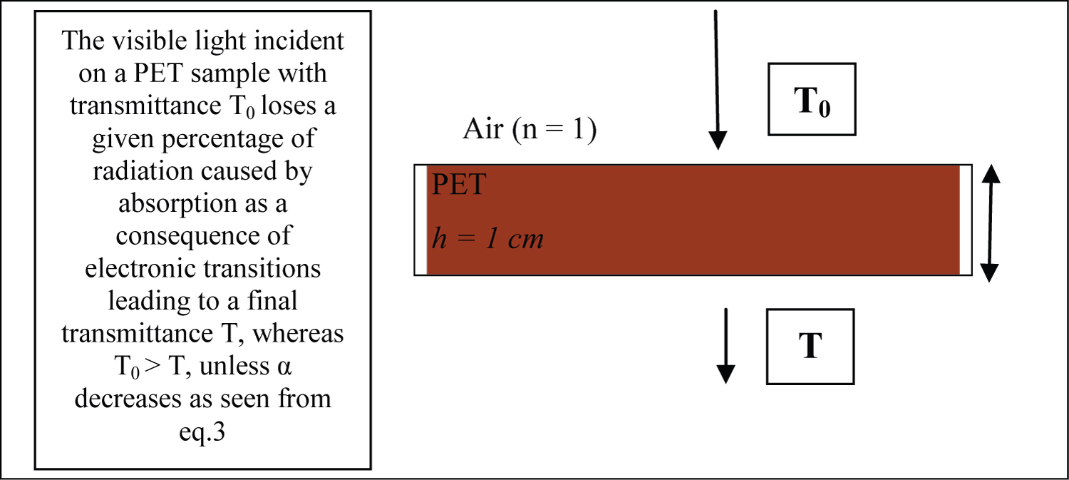
Figure 1: Interaction of light with the....
Interaction of light with the sample containing a thin film of thickness h.
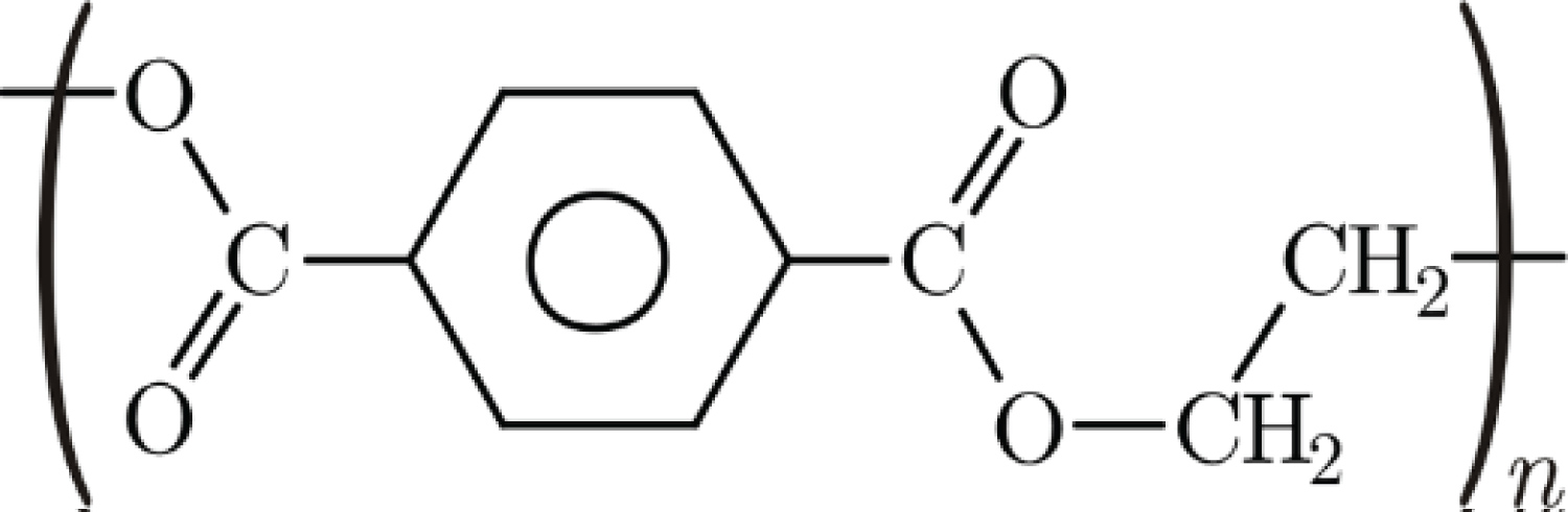
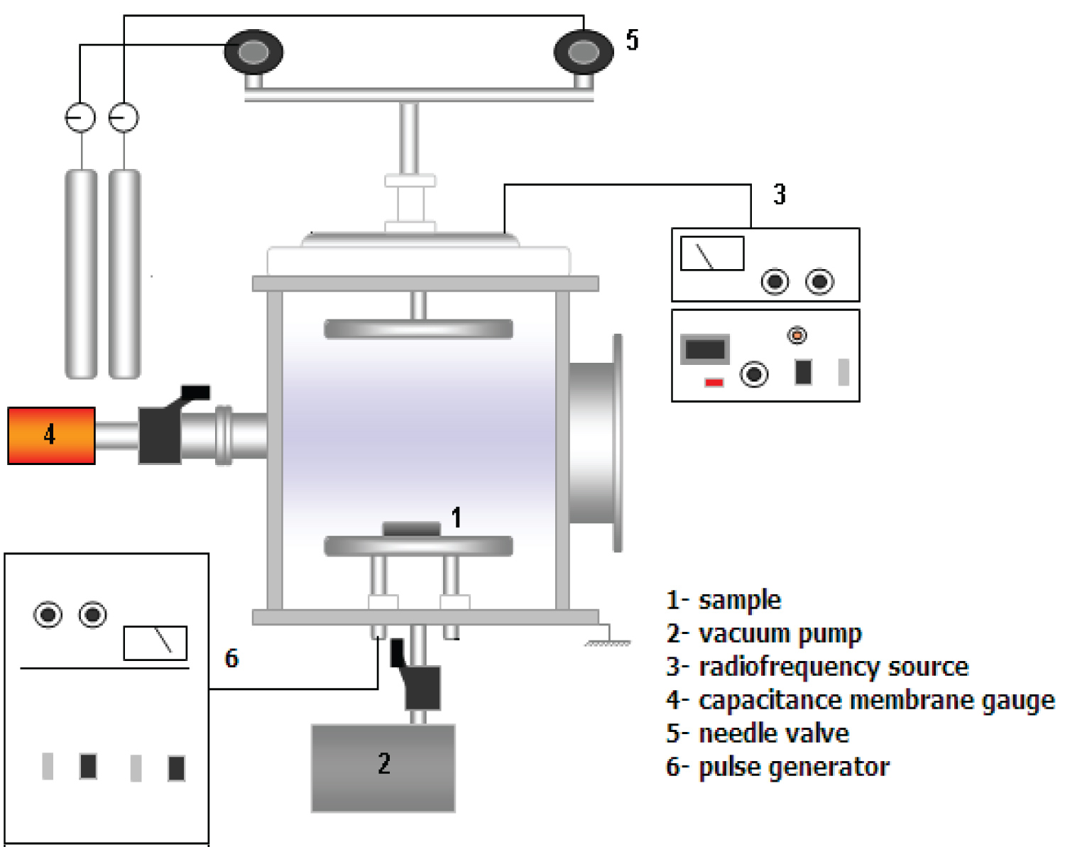
Figure 3: Electrical configuration of plasma....
Electrical configuration of plasma immersion techniques applied in the experiments. Plasma Immersion and Plasma Immersion Ion Implantation.
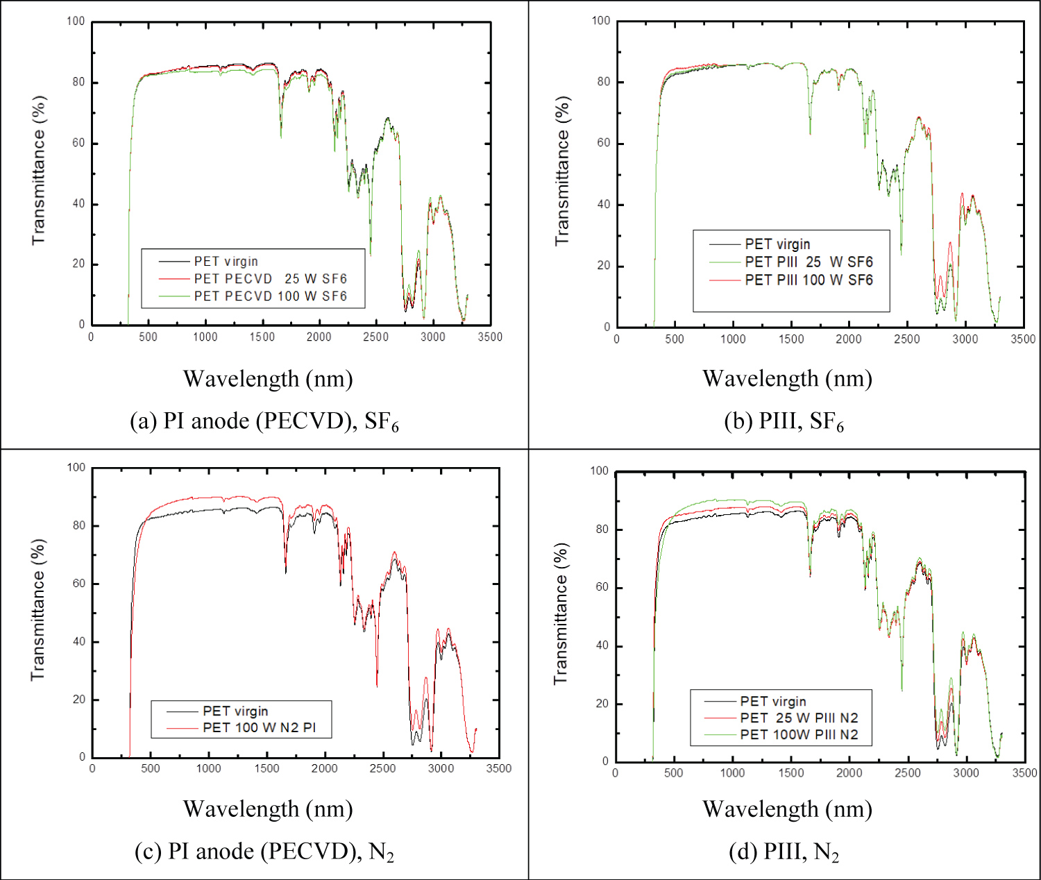
Figure 4: Optical transmittance of untreated....
Optical transmittance of untreated (virgin) PET and treated with SF6 and N2 plasmas in PI anode (PECVD) and PIII.

Figure 5: ɵ evolution with aging time of PET surfaces....
ɵ evolution with aging time of PET surfaces that were exposed to SF6 plasma for 900 s, at 25 W and 100 W of RF Power.
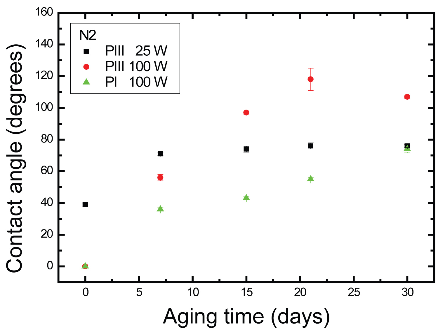
Figure 6: ɵ evolution on aging time of PET surfaces....
ɵ evolution on aging time of PET surfaces that were exposed to N2 plasma for 900 s, at 25 W and 100 W of RF Power.
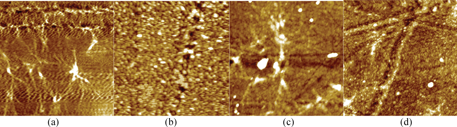
Figure 7: AFM images of PET treated by SF6 Plasma....
AFM images of PET treated by SF6 Plasma (a) untreated, R = 1.8 nm (b) 100 W, PI cathode, R = 4.7 nm (c) treated with 6.56 Pa, 25 W, PIII, R = 2.6 nm (d) 150 W, PIII, R = 2.5 nm. Parameters of High Voltage: - 2400V, 30 μs, 300 Hz.
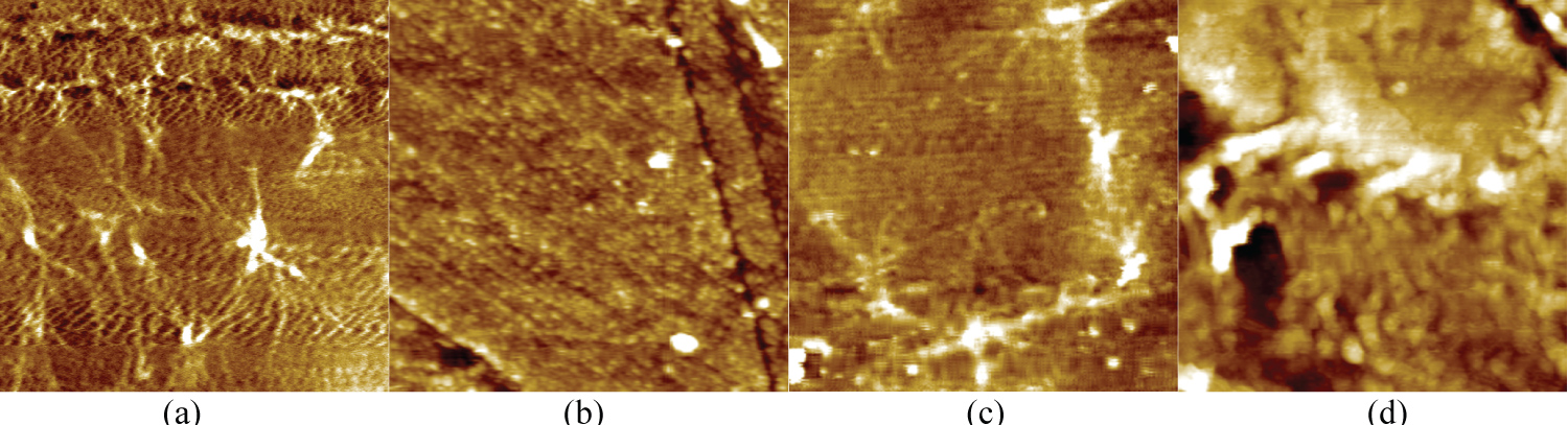
Figure 8: AFM images of PET treated by N2 Plasma....
AFM images of PET treated by N2 Plasma (a) untreated, R = 1.8 nm (b) 100 W, PI, R = 4.4 nm (c) 25 W, PIII, R = 1.4 nm (d) 75 W, PIII, R = 1.7 nm. Parameters of High Voltage: - 2400V, 30 μs, 300 Hz.
Tables
Table 1: Plasma immersion procedure conditions for the PET samples.
Table 2: Absorption of some chromospheres' or radicals groups which contain C, H, O or N, and can be formed on surface of PET caused by ion bombardment during plasma treatment [31].
Table 3: Treatment conditions and contact angle of deionized water, surface roughness and optical transmittance at 550 nm.
References
- Rokka J, Uusitalo L (2008) Preference for green packaging in consumer product choices - Do consumers care? International Journal of Consumer Studies 32: 516-525.
- Salmi MI, Pung XY (2013) Investigating the preference for green packaging in consumer product choices: A choice-based conjoint approach. Business Management Dynamics 3: 84-96.
- Mieth A, Hoekstra E, Simoneau C (2016) Guidance for the identification of polymers in multilayer films used in food contact materials: User guide of selected practices to determine the nature of layers, JRC100835.
- Sant'Ana PL (2018) Polymers treated by plasma for optical devices and food packaging. Scholar’s Press.
- Rabies A, Shanduka’s S (2013) Processing and evaluation of bioactive coatings on polymeric implants. J Biomed Mater Res A 101: 2621-2629.
- Hahn B-D, Park D-S, Choi J-J, Ryu J, Yoon W-H, et al. (2013) Osteoconductive hydroxyapatite coated PEEK for spinal fusion surgery. Applied Surface Science 283: 6-11.
- Novák I, Chodák IJ, Sedlia IK, Števiar M, Popelka A, et al. (2010) Investigation of poly(ethylene terephthalate) treated by low-temperature plasma. Annals of Warsaw University of Life Sciences - SGGW, Forestry and Wood Technology 72: 83-89.
- Sant’Ana PL, Bortoleto JRR, Cruz NC, Rangel EC, Durrant SF (2017) Study of wettability and optical transparency of PET polymer modified by plasma immersion ion implantation techniques. Revista Brasileira de Aplicações de Vácuo 36: 68-74.
- Pankaj SK, Bueno-Ferrer C, Misra NN, Milosavljevic V, O’Donnell CP, et al. (2014) Applications of cold plasma technology in food packaging. Trends Food Sci Technol 35: 5-17.
- Gorjanc M, Savic A, Topalic-Trivunovic L, Mozetic M, Zaplotnik R, et al. (2016) Dyeing of plasma treated cotton and bamboo rayon with fallopia japonica extract. Cellulose 23: 2221-2228.
- Gorjanc M, Jazbec K, Sala M, Zaplotnik R, Vesel A, et al. (2014) Creating cellulose fibres with excellent UV protective properties using moist CF4 plasma and Zno nanoparticles. Cellulose 21: 3007-3021.
- Lopez-Garcia J, Primc G, Junkar I, Lehocky M, Mozetic M (2015) On the hydrophilicity and water resistance effect of styrene-acrylonitrile copolymer treated by CF4 and O2 Plasma Process Polym 12: 1075-1084.
- Lopez-Garcia J, Lehocky M, Humpolicek P, Novak I (2014) On the correlation of surface charge and energy in non-thermal plasma-treated polyethylene. Surf Interface Anal 46: 625-629.
- Gorjanc M, Mozetic M (2014) Modification of fibrous polymers by gaseous plasma: Principles, techniques and applications. Lambert Academic Publishing, Saarbrücken, Germany.
- Primc G, Tomsic B, Vesel A, Mozetic M, Razic SE, et al. (2016) Biodegradability of oxygen-plasma treated cellulose textile functionalized with Zno nanoparticles as antibacterial treatment. J Phys D Appl Phys 49: 324002.
- Gorjanc M, Sala M (2016) Durable antibacterial and UV protective properties of cellulose fabric functionalized with Ag/TiO2 nanocomposite during dyeing with reactive dyes. Cellulose 23: 2199-2209.
- Popelka A, Novak I, Lehocky M, Bilek F, Kleinova A, et al. (2015) Antibacterial treatment of LDPE with halogen derivatives via cold plasma. Express Polym Lett 9: 402-411.
- Asadinezhad A, Novak I, Lehocky M, Sedlarik V, Vesel A, et al. (2010) Physicochemical approach to render antibacterial surfaces on plasma-treated medical-grade PVC: Irgasan coating. Plasma Process Polym 7: 504-514.
- Sulovska K, Lehocky M (2014) Characterization of plasma treated surfaces for food safety by terahertz spectroscopy. Proc SPIE 9252: 925209.
- Nazarov VG, Stolyarov VP, Gagarin MV (2014) Simulation of chemical modification of polymer surface. Journal of Fluorine Chemistry 161: 120-127.
- Kharitonov AP, Simbirtseva GV, Tressaud A, Durand EC, Labrugère MD (2014) Comparison of the surface modifications of polymers induced by direct fluorination and rf-plasma using fluorinated gases. Journal of Fluorine Chemistry 165: 49-60.
- Fellows JP (2006) Tecnologia do processamento de alimentos: Princípios e prática. (2nd edn), Artmed, Porto Alegre.
- Williams R (1989) Applications of Fourier transform spectrometry in the ultraviolet, visible, and near-IR. Applied Spectroscopy Reviews 25: 63-79.
- Torres J, Cisneros JI, Gordillo G, Alvarez F (1996) A simple method to determine the optical constants and thickness of ZnxCd1-x thin films. Thin Solid Films 289: 238-241.
- Siddhartha, Suveda A, Kapil D, Suresh KR, Krishna JBM, Wahab MA (2012) Effect of gamma radiation on the structural and optical properties of Polyethyleneterephthalate (PET) polymer. Radiation Physics and Chemistry 81: 458-462.
- Turner JE (2004) Interaction of ionizing radiation with matter. Health Phys 86: 228-252.
- Junkar I, Cvelbar U, Vesel A, Hauptman N, Mozetic M (2009) The role of crystallinity on polymer interaction with oxygen plasma. Process Poly 6: 667-675.
- Sant’Ana PL, Bortoleto JRR, Cruz NC, Rangel EC, Durrant SF, et al. (2020) Surface properties of low-density polyethylene treated by plasma immersion ion implantation for food packaging. Rev Bras Apl Vac 39: 14-23.
- Ziegler JF, Biersack JP (1985) The stopping and range of ions in matter. In: Bromley DA, Treatise on heavy-ion science. Springer,
- Dong H, Bell T (1999) State-of-the-art overview: Ion beam surface modification of polymers towards improving tribological properties. Surf Coat Tech 111: 29-40.
- Vinade´ MEC, Vinade´ ERC (2005) Quantitative analysis of spectroscopic methods.
- Lee EH (1999) Ion-beam modification of polymeric materials - fundamental principles and applications. Nucl Instrum Meth B 151: 29-41.
- Durrant SF, Mota RP, de Moraes MAB (1992) Relationships between the plasma environment and the composition and optical properties of plasma-polymerized thin films produced in rf discharges of C2H2-SF6 Journal of Applied Physics 71: 448.
- Durrant SF, de Oliveira RT, Castro SGC, Bolivar-Marinez LE, Galvao DS, et al. (1997) Structural and optical properties of plasma-deposited amorphous hydrogenated oxygenated carbon films. J Vac Sci Technol A 15: 1334-1339.
- Tho SY, Ibrahim K (2012) Influence of surface roughness of Polyethylene Terephthalate (PET) substrate to the morphology and optical properties of coated zinc oxide thin-film. Jurnal Teknologi 59: 5-8.
- Larena A, Millán F, Pérez G, Pinto G (2002) Effect of surface roughness on the optical properties of multilayer polymer films. Applied Surface Science 187: 339-346.
- Yazdanian M, Ward IM, Brody H (1985) An infra-red study of the structure of oriented poly(ethylene terephthalate) fibres. Polymer 26: 1779-1790.
- Quintanilla L, Rodríguez-Cabello JC, Tawhari T, Pastor JM (1993) Structural analysis of injection-moulded semicrystalline polymers by Fourier transform infra-red spectroscopy with photoacoustic detection and differential scanning calorimetry: 1. Poly(ethylene terephthalate). Polymer 34: 3787-3795.
- Manley TR, Williams DA (1969) Structure of terephthalate polymers I - Infra-red spectra and molecular structure of poly (ethylene terephthalate). Polymer 10: 339-384.
- Nogi M, Changjae K, Tohru S, Tetsuji I, Tsukasa T, et al. (2013) High thermal stability of optical transparency in cellulose nanofiber paper. Appl Phys Lett 102: 181911.
- Field D, Sternhell S, Kalman JR (2008) Organic structures from spectra. (4th edn), John Wiley & Sons Ltd, Chichester, England.
- Muranyi P, Wunderlich J, Langowski HC (2010) Modification of bacterial structures by a low-temperature gas plasma and influence on packaging material. J Appl Microbiol 109: 1875-1885.
- Basaran P, Basaran-Akgul N, Oksuz L (2008) Elimination of Aspergillus parasiticus from nut surface with low pressure cold plasma (LPCP) treatment. Food Microbiol 25: 626-632.
- Niemira AB (2012) Cold plasma reduction of Salmonella and E.coli O157:H7 on almonds using ambient pressure gas. J Food Sci 77: 171-175.
Author Details
Péricles Lopes Sant'Ana*, José Roberto Ribeiro Bortoleto, Elidiane Cipriano Rangel, Nilson Cristino da Cruz and Steven F Durrant
Instituto de Ciência e Tecnologia de Sorocaba, São Paulo State University, UNESP, Brazil
Corresponding author
Péricles Lopes Sant'Ana, Sorocaba Institute of Science and Technology, São Paulo State University, UNESP, Três de Março Av. 511, Alto da Boa Vista, 18087-180, Sorocaba, SP, Brazil
Accepted: May 26, 2021 | Published Online: May 28, 2021
Citation: Sant'Ana PL, Bortoleto JRR, Rangel EC, Cruz NC, Durrant SF (2021) Increase in Optical Transmittance of Polyethylene Terephthalate Treated by Plasma Immersion Techniques for Packaging Applications. Int J Opt Photonic Eng 6:033
Copyright: © 2021 Sant'Ana PL, et al. This is an open-access article distributed under the terms of the Creative Commons Attribution License, which permits unrestricted use, distribution, and reproduction in any medium, provided the original author and source are credited.
Abstract
In this work the optical transmittance in the visible region of Polyethylene Terephthalate treated by plasma immersion techniques was studied. This material was chosen as the substrate because of its flexibility, low cost and high transmission in the visible part of the electromagnetic spectrum, properties suitable and necessary for packaging applications, especially optical transparency, since consumers want to inspect the product. Therefore, Plasma Immersion and Plasma Immersion Ion Implantation techniques using sulfur hexafluoride and nitrogen plasmas were applied to increase optical transmittance in the visible range while maintaining the temperature at about 300 K. The reactor pressure was 50 mTorr (6.66 Pa) and different radiofrequency (rf) powers were applied for 900 s. An improvement in optical transmittance to ~ 86% was obtained in the visible region for treated PET compared to the pristine material.
Keywords
PET, Plasma immersion, Plasma immersion ion implantation, Optical transmittance, Food packaging
Introduction
Polyethylene terephthalate as packaging material
Packaging has a fundamental role in ensuring the safe delivery of goods throughout supply chains to the end consumer. As reported by Rokka and Uusitalo [1], increasing environmental concern among consumers in their selection of food products also includes the packaging. Packaging plays an important role in preserving and protecting products during their storage, transport and use [2]. Mieth, et al. [3] list the most common polymers in packaging materials, their functions in the packaging and some applications. Among packaging materials, Polyethylene Terephthalate (PET) is characterized by excellent resistance to a variety of chemicals, including aliphatic hydrocarbons, gasoline, fats, alcohols, glycols, ethers, esters, ketones, diluted acids and bases, detergents and most aqueous salt solutions [4].
PET is relatively cheap, non-toxic and has medium permeability to moisture and gases, especially carbon dioxide and oxygen. These characteristics associated with the others related to its different degrees of crystallinity give PET a set of properties that makes it attractive for use as food packaging, be it in films, trays or bottles. In addition to its use in the carbonated beverage market, PET has been used as packaging for wine, beer, fruit juice, edible oil, mineral water, soluble coffee, yogurt, salad dressing, ready meals, and in isotonic and alcoholic beverages [4].
Surface treatment of polymer for packaging applications
There are many techniques that can be used to alter the surface properties of packaging materials by addition of particles, i.e., coatings and functional groups [5,6]. New techniques are often applied to improve the surface properties of food packaging. Recent results from PET treated in atmospheric plasmas at low temperature were presented by Novák, et al. [7]. Sant'Ana, et al. [8] recently showed the improvement of wettability, and the changes in surface roughness and optical transmittance in the visible region of PET (from Coke™ bottles) treated by plasma immersion techniques. Plasma treatments cause several chemical and physical changes on the plasma-polymer interface, which improve the surface properties [9-13]. Such induced changes are nowadays exploited in surface functionalization of packaging polymers, for promoting printability [14], assuring anti-mist properties, and creating antibacterial coatings [15-19]. Surface modification using reactive gases is simple, rapid, and efficient, and allows control of the process rate [20].
Radiofrequency (rf) plasma technologies using fluorinated gases are currently employed in materials science, presenting advantages such as low-temperature reactions (in many cases the treatment can be achieved at room temperature, which avoids thermal degradation of the material). Direct fluorination is an effective method for improving the surface properties of pristine polymer materials, including barrier properties, adhesion, printability, gas separation properties, chemical resistance, antibacterial properties (biocompatibility), etc. [21]. In particular, PECVD (Plasma Enhanced Chemical Vapor Deposition) allows the production of thin films with a wide range of properties through the control of the process parameters. Examples include insulating/conductive layers, which are used in the manufacture of electronic devices, transparent films suitable for application as optical windows, anti-reflective layers, coatings of lenses or sports glasses and biocompatible films and hydrophobic materials suitable for applications in food packaging or solar cells [8].
More intense changes are obtained when the sample is exposed to plasma subjected to polarized pulses of high negative voltage, thus attracting positive ions. The interaction of these energetic ions with the atoms of the solid can cause excitation, ionization, fragmentation of chemical bonds, emission of species and atomic displacements, inducing compositional changes and structural rearrangements. This process is known as Plasma Immersion Ion Implantation (PIII) and was created to overcome certain limitations of conventional implantation with ion beams. The efficiency of PIII and the induced changes in the properties of polymeric materials have been reported [8]. To our best knowledge there is no known surface treatment able to improve the optical transmission of food packaging in the visible region. Thus, in this work the optical transmittance in the visible region of PET treated by plasma immersion and PIII was studied.
The motivation is to find a technological application of the recycled material. To our best knowledge there is no extant literature on a surface treatment able to improve T (λ) in the visible range, except the report by Sant'Ana [4]. In packaging applications the consumers want to be able to visibly inspect the product.
Ultraviolet-visible near infrared spectroscopy
The transmission of light is necessary in packaging whose purpose is to show the content but must be controlled when food is susceptible to deterioration by light (for example: lipid oxidation, destruction of vitamins and natural pigments). The amount of light absorbed or transmitted varies with the packaging material and the wavelength of the incident light. The fraction of light transmitted by a packaging material can be found using equation (1) [22]:
In which It = Intensity of light transmitted by the package; Ii = Intensity of light incident on the packaging; α = Absorption coefficient of the packaging material; h = Thickness of the packaging material.
Optical spectroscopy can provide some characteristics of thin films, such as thickness and optical constants. Optical constants describe how light is reflected or propagated through a material. Optical techniques that allow the analysis of thin films are typically accurate, non-destructive and require little or no sample preparation. Measurements can be performed using the transmittance or light reflectance method [23]. From the transmittance spectrum, the optical constants and the film thickness may be determined.
One way of calculating the ratio of the light intensity through the film sample (T) to the incident light intensity (T0) is to use Equation 2, where h is the deposited film thickness, k, A, B, C and D are constants related to the refractive index of air, thin film or substrate [24]. There is no correlation between these constants. Equation 3 shows that T intensity depends on T0 intensity, the absorption coefficient, α(E), film thickness, h, and the reflectance, R. Figure 1 shows a schematic of the set-up.
Experimental Details
The experimental setup consisted of a stainless-steel vacuum chamber (30 cm in height and 25 cm in diameter) with two internal, horizontal, circular electrodes of equal dimension (11 cm in diameter). PET substrates from a 2 L Coke™ bottle were cleaned in an ultrasound cube and placed on the stainless-steel electrode. The system was evacuated by an oil rotary pump (18 m3/h) from Edwards to a base pressure of to 0.1 Pa. Needle valves were employed to control the SF6 or N2 flows (both gases were of 99.9995% purity), and a capacitive pressure sensor used to monitor the chamber pressure. Samples were exposed directly to the plasma environment established by the application of rf power (13.56 MHz). Nine substrates of blue PET (2.5 cm × 1.5 cm × 1 cm) were treated using the same process, in two different rf plasma immersion modes, summarized as follows:
i. The sample holder and the chamber walls were grounded while rf power was connected to the opposite electrode (driven electrode): PI 'anode', the same configuration of PECVD (Plasma Enhanced Chemical Vapor Deposition).
ii. The rf power was connected to the upper electrode (driven electrode) while negative pulses of high voltage were applied to the substrate holder: PIII. A high voltage source model RUP-6 and a TDS oscilloscope from Tektronics were employed for the PIII experiments. A negative voltage of -2400 V at 300 Hz was used. ton and toff and were fixed at 30 μs for all PIII experiments, yielding a duty cycle of 0.01. In this configuration it is also possible to deposit a thin film, characterizing the procedure as PIIID (Plasma Immersion Ion Implantation and Deposition). Using Atomic Force Microscopy and taking 5 μm × 5 μm scans, seven samples were treated. Figure 2 shows the chemical structure of PET.
Figure 3 shows the electrical configuration of the plasma immersion (PI or PECVD) and plasma immersion ion implantation (PIII or PIIID) procedures. *PI and PECVD have the same electrical configuration as PIII and PIIID (Table 1).
Results and Discussion
To observe the effect of the plasma surface treatment on the transparency of the PET samples, optical transmittance spectra of seven treated samples were measured, and compared to that of an untreated sample. Figure 4 shows the optical transmittance spectrum as a function of wavelength for untreated PET and PET treated.
High transmittances were observed (> 80%) for wavelengths from ~500 to 1500 nm. Some increase in transmittance was observed for the treatments PIII SF6, PI anode N2 and PIII, N2. The absorption coefficient, α(E), of PET typically varies from 10 to ~700 cm-1 for photon energies between 2 and 4.25 eV [25]. PET samples from a 2 L. Coke™ bottle were treated by PECVD and PIII using SF6 or N2 without a cooling system, so that the plasma temperature reached 60 °C at 25 W and 80 °C at 100 W. The optical transmittance fell from 80% to 40% in the visible region. According Sant'Ana, this change was associated with the effect of the temperature inside the reactor during the treatments [8]. It is observed that the transmittance remains practically constant in the wavelength, λ, range of 400 to 700 nm (visible) and progressively decreases for λ below 400 nm; however, a great loss in visible light transmission was noted independently of the gas employed. At high powers there is greater bond breaking, and subsequently recombination between different species of the plasma, causing greater distortions and rearrangement of the chains. Free radicals and dangling bonds left in the structure tend to rearrange to minimize their concentration. This reorganization might result in unsaturated carbon double (C=C) and triple bonds (C≡C), or processes of entanglement or cross-linking via covalent bonds when radicals are created in adjacent chains, thus decreasing the free passage of the incident radiation [26].
More intense alterations can be observed in the spectra of the samples subjected to the process of PIII. As an energetic ion penetrates the material, it transfers energy to the polymer structure through the mechanisms of electronic braking and nuclear braking. By electronic braking, the ions transfer enough energy to the polymer structure to trigger processes of excitation, ionization, vibration and bond breaking. Breakage of connections usually occurs in side groups, releasing chemical species into the structure, such as H, N, O, CO, CHx [27]. The same effect of transmittance loss was observed in Low Density Polyethylene when treated by PIII [28]. Although both electronic and nuclear processes cause crosslinking as well as scissions, it has been found that the most important parameter to achieve a high degree of crosslinking is electronic, while nuclear collisions tend to cause degradation [29]. For a given energy, smaller ions penetrate deeper and cause fewer nuclear displacements than heavier ones. These changes are irreversible in the structure of the treated polymer and, consequently, in its superficial physicochemical properties [30].
The effect of undesired warming during plasma treatment can be avoided using a cooling system during the treatments. A high optical transmittance is associated with low absorption for smooth surfaces. PET is a covalently bonded material of C, H or O, containing single or double bonds (chromophores). Table 2 shows possible radicals on PET after treatments with or without nitrogen treatment, and, for all cases, absorptions occur below ~ 330 nm, which explains the low values of T (λ) in this region.
The literature reports the loss of optical transmittance of visible light T(λ) as a consequence of adjacent carbon chains (crosslinks), acting as a barrier to the free path of radiation through the polymeric lattice. As a result of plasma treatment and ion implantation, anchor points can be formed which approximate adjacent chains and, then, may fill voids contained in the structure of the polymer chains [32]. In PIII, ions are projected into the polymer matrix in discrete quantity, lodging in its vacancies (regions not occupied by atoms or molecules).
For plasma films deposited from C2H2-SF6 mixtures the fluorinated films show reduced absorption coefficients compared to the unfluorinated films for photon energies between 0.5 and 4 eV [33]. This suggests that the incorporation of F, giving rise to C-F bonds, is part of the cause in the fall in α(E). A partial explanation for this is that F forms σ bonds with carbon and decreases the number of π bonds. The loss of H caused by ion impacts may also influence the proportion of π and σ bonds. Similar effects are a possible explanation for the reduction in the absorption coefficient produced by the SF6 plasma treatment.
Considering the nitrogen plasma treatments, even though oxygen is not deliberately introduced into the feed, there is a residual contribution from the base pressure and the samples are exposed to ambient conditions upon removal from the treatment chamber. In addition, it is known from the literature that for films deposited from C2H2-O2-Ar mixtures [34], greater oxygen incorporation generally leads to lower absorption coefficients. Owing to the high electronegativity of oxygen, the modifications in bond lengths are more pronounced than those caused by hydrogen [35], which might explain why the absorption in our polymers decreased as the C-H bonds were replaced by C-O bonds.
Table 3 shows the contact angle as a function of time, measured by a Ramé-Hart100-00 Goniometer, using the sessile drop method [4], and beginning immediately after the removal of PET samples from the reactor. Surface roughness Rrms was examined by a model XE-100 AFM from Park Instruments. Optical transmittance was measured at 550 nm using a Lambda 750 UV-VIS-NIR Spectrometer from Perkin Elmer.
As already noted, increased surface roughness tends to increase surface scattering, which will tend to reduce the transmittance [36].
Infrared spectra of samples in the range of wavenumber from 650 to 1000 cm-1 show bands very well studied in the literature for the characterization of PET [37,38]. According Manley and Williams, the intensity of these bands is moderately independent of the surface roughness of the target material [39]. AFM scans taking 5 μm × 5 μm of PET samples revealed that the surface roughness is low, and therefore the high optical transmittance only can be associated with a decrease in the absorption coefficient.
The water contact angle decreased initially with the treatment time. In Figure 5 this tendency is attenuated for the treatments using fluorine. The best performance of this work can be observed in those “curves”, especially using PIII and in PI cathode at 100 W.
Sample treatment with SF6 was chosen because it produces hydrophobic surfaces. The hydrophobic surface properties might be increased and stabilized owing to the replacement of C-H bonds or oxygen-containing groups by C-F bonds or even CF2 and CF3 groups. Although C-F bonds are highly polar, these species when present on the surface of a material will increase the hydrophobicity. It has been demonstrated that fluorination of PET surfaces can be achieved through fluorine radicals generated in sulfur hexafluoride plasmas.
Figure 6 shows the values of contact angle, as a function of the aging time for samples treated with N2 using the three different techniques. Glow discharge plasma-based treatments are of particular interest because they allow surface hydrophilization without inducing bulk modifications. The atoms from the surface can react with oxygen and water in air after the treatment to form oxygen-containing groups, and therefore turn the surfaces into hydrophilic ones. The highest value of contact angle occurred for 100 W of RF Power by PIII at 100 W (~120°) after 21 days of aging time, while the lowest value of ɵ, was 0°. Polymeric chains have freedom of movement and consequently, they can turn polar groups towards the surface. Moreover, molecules from the bulk can migrate towards the surface.
The 2D AFM surface morphology of the PET samples before and after the plasma treatment with SF6 or N2 are shown in Figure 7 and Figure 8, respectively. For the conditions specified in the captions (of Figure 7 and Figure 8) an ion penetration depth of 100 to 200 Å is expected.
The AFM images reveal that the surface of the PET substrates is relatively smooth, that is, it presents a regular morphology. In fact, the Rrms of the PET was 1.8 nm for these AFM images. In addition, the PET surface is free of pinholes. In this aspect, the PET substrates, containing in their structure, aromatic rings or double bonds, are therefore more rigid and thus, offer greater resistance to ionic bombardment, even at 150 W of rf treatment (more energetic), and the morphological changes induced by the ion bombardment are more subtle; consequently, the Rrms. roughness values were in fact smaller compared to PVC roughness values. Again, in PIII ions tend to lodge some tens of nanometers under the top layers of the polymeric chains, being an efficient mechanism for surface roughening. Ions accelerated from plasma towards a surface tend to break the peaks, thus reducing Rrms. There are surface scratches that derive from the original cleaning process.
A series of treatments of PET by PECVD and PIII, maintaining the substrate holder at room temperature (using a cooling system), employing the same gases SF6 and N2 at 25 to 100 W, was undertaken. Immediately after the treatments a digital thermometer measured the temperature of the sample holder as 25.5 °C. In all cases, high transmittances of up to ~82% were reached, using the same spectrometer under the same conditions. Consequently, for constant R, T increases if A decreases; hence, the absorption coefficient must decrease.
For opto-electronic applications, the transparent substrates must be able to maintain their high optical transparency after high temperature heating, caused by plasma processes. This is a serious issue for flexible polymer substrates. PET films are colorless, transparent (refractive index = 1.8564), and cheap, but do not have enough thermal durability for the above-mentioned high temperature process [40]. In this same study, a high transmittance (close to 89%) and low reflection (4.5, obtained after N2 plasma treatment, were measured for PET. Strong absorption by carbonyl groups and its derivatives occur in the range from 200 to 350 nm [41] and at other low wavelengths in PET. The resulting material has potential in food packaging, combining selective wettability and stability, low roughness and high optical transmittance in the visible range. PET also has the advantage that it may be recycled. Plasma is also involved in the decontamination of the surfaces of packaging material and even prevents the post-packaging contamination of the food product. Muranyi, et al. reported reductions of Aspergillus niger & Bacillus subtilus in plasma-treated PET foils [42].
Conclusions
In this work the optical transmittances of commercial PET samples, untreated and treated with SF6 and N2 plasmas by PECVD and PIII, maintaining the sample holder at ambient temperature, were studied. PET samples treated at 25 °C presented an increase to 86% in the visible region, and at the same time, low surface roughness Rrms < 5 nm, and presented high contact angles using SF6 (> 120°), and low contact angles (< 40°) using N2 plasma. This effect occurs at both low and high rf power and is more marked in nitrogen plasmas.
As the sample surface is smooth and not greatly affected by the treatments, R(reflectance) is fixed (or even increases slightly), but A + R + T = 1. Therefore, if T increases, then A decreases. Thus the coefficient of absorption decreases. The reduction in α(E) may be caused by the incorporation of F or O into the treated PET and to other structural rearrangements induced by SF6 and N2 plasmas, respectively. It is known that a-C:H:F films typically have lower α(E) values than those of a-C:H films [33]. This may explain in part the improved transmittance of PET treated by PIII. The greatest improvements in transmittance, however, were observed with the treatments in nitrogen plasmas. These improvements may be caused by the opening of the polymer structure, the release of hydrogen, the incorporation of more oxygen into the polymer structure, or some combination of these. The incorporation of oxygen into substrates in plasmas not deliberately containing oxygen is well known. That this additional oxygen may reduce α is supported by α(E) curves obtained for PECVD films of C6H6-Ar-He-O2 mixtures as a function of the partial pressure of oxygen in the feed [34]. Owing to the high electronegativity of oxygen, the modifications in bond lengths are more pronounced than those caused by hydrogen [33]. This might explain why the absorption in the treated PET decreased as the C-H bonds were replaced by C-O or C=O bonds.
In addition to the improved optical properties, plasma treatment is suitable for cleaning and disinfection of packaging polymers. The asepsis is an important feature for food packaging. It has been observed that sulfur hexafluoride plasmas reduce the growth of A. parasiticus [43] while nitrogen plasmas reduce E. coli [44].
Acknowledgements
The authors are grateful to the Brazilian agencies FAPESP (Project 2017/15853-0) and CNPq for financial support. This work was supported in part by CAPES (finance code 001).
Availability Statement
The data that support the findings of this study are available from the corresponding author upon reasonable request.