
International Journal of Robotic Engineering
(ISSN: 2631-5106)
Volume 4, Issue 1
Research Article
DOI: 10.35840/2631-5106/4119

Article Formats
Design and Simulation of a Collaborative Propulsion System for the Underwater Robot
Table of Content
Figures

Figure 1: Different streamlines of underwater robots....
Different streamlines of underwater robots.
Figure 2: Conceptual design of underwater robot equipped...
Conceptual design of underwater robot equipped with the collaborative propulsion system.
Figure 3: The inside structure of the Coanda effect based...
The inside structure of the Coanda effect based primary propulsion system.

Figure 5: Two-dimensional schematic of jet steering...
Two-dimensional schematic of jet steering control valve.
Figure 7: Internal feature structure of the fluidic valve...
Internal feature structure of the fluidic valve: a) Sidewall slope of 12 degrees; b) Concave wedge.

Figure 11: Overview structure of the auxiliary propulsion system....
Overview structure of the auxiliary propulsion system.
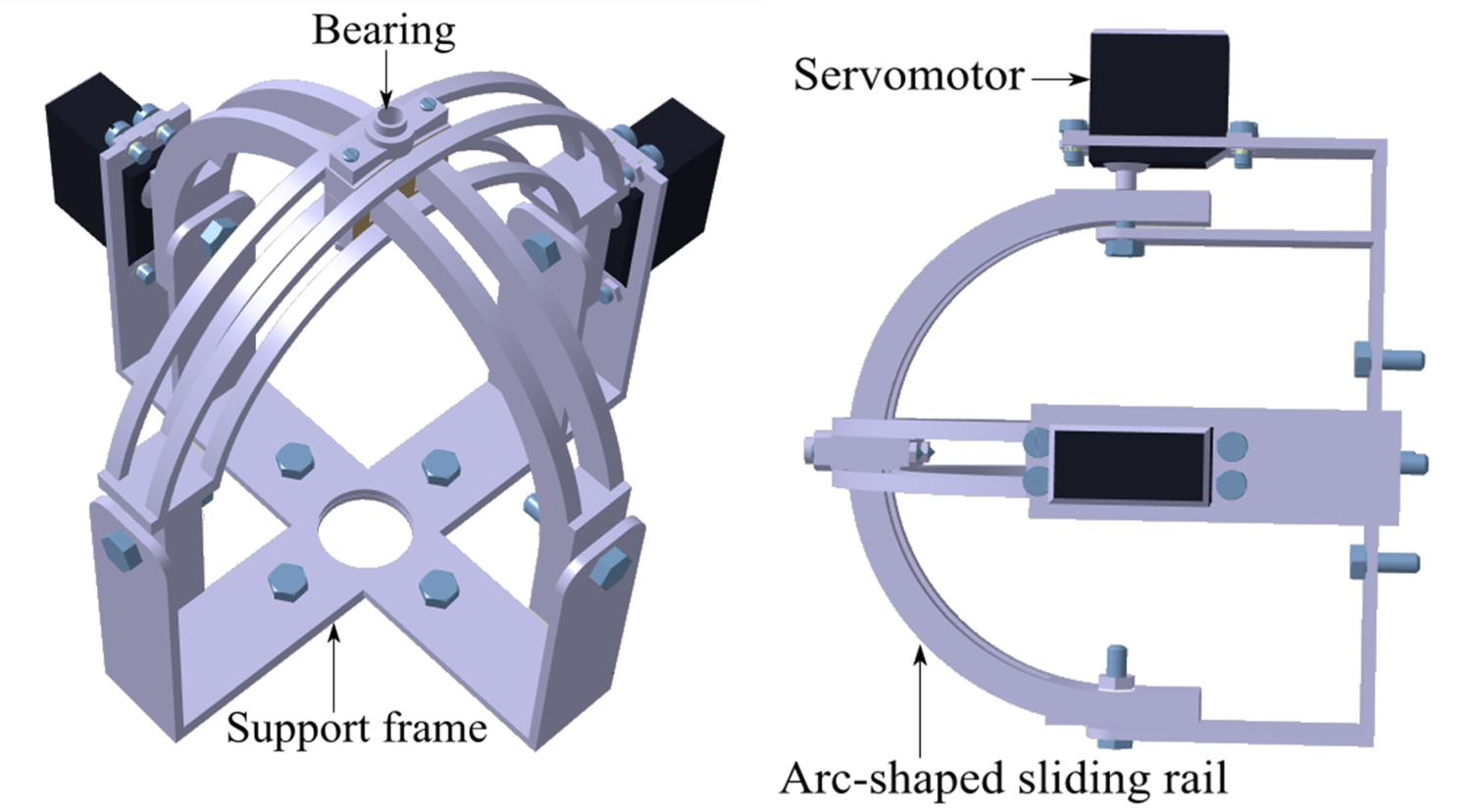
Figure 12: The vectored steering mechanism: a) Front view; b) Side view....
The vectored steering mechanism: a) Front view; b) Side view.
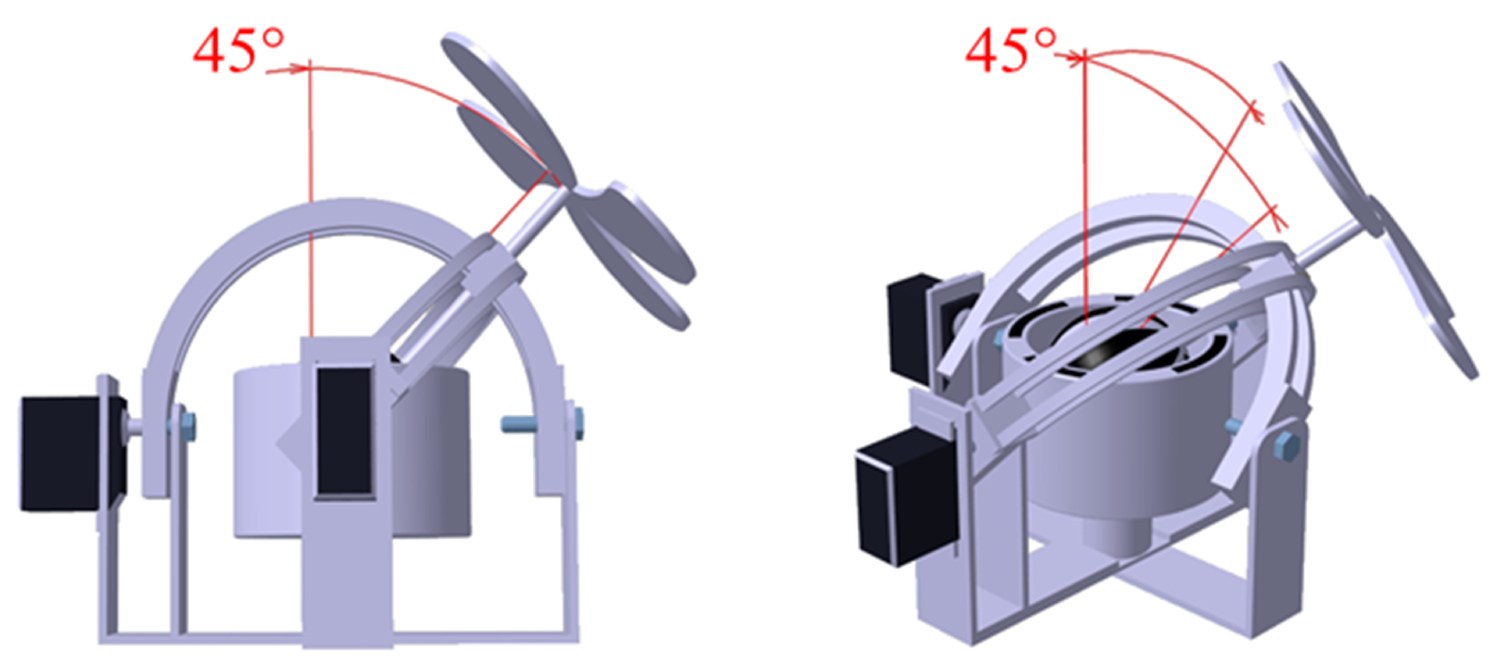
Figure 13: Conversion KEMP(O15) = > KTH(Ca39), calculated...
Schematic diagram of thrust adjustment range: a) RMC device using one sliding rail with the deflection angle of 45°; b) RMC device using two sliding rails with the deflection angle of 45°.
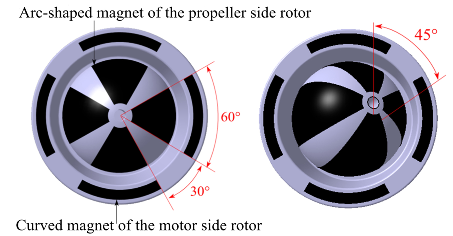
Figure 14: The structure of magnetic coupling: a) Top...
The structure of magnetic coupling: a) Top view with the deflection angle of 0°; b) Top view with the deflection angle of 45°.
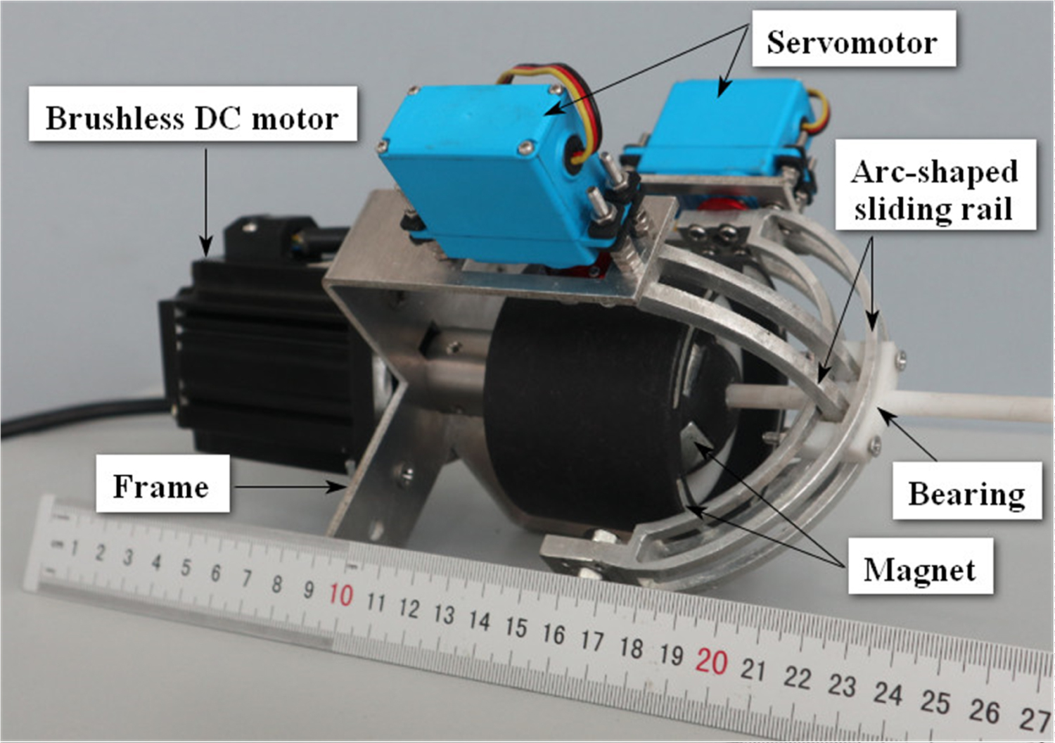

Figure 16: Relation between jet attachment efficiency...
Relation between jet attachment efficiency η and inlet flow velocity V1.


Figure 18: Relation between jet attachment efficiency...
Relation between jet attachment efficiency η and control port flow velocity V2.
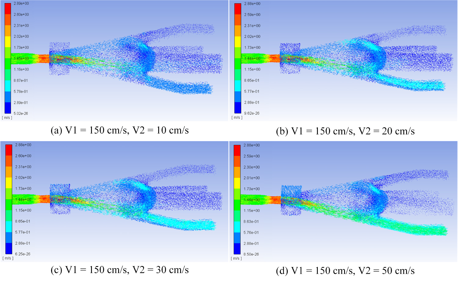
Figure 19: Effect of control port flow velocity on jet...
Effect of control port flow velocity on jet attachment.
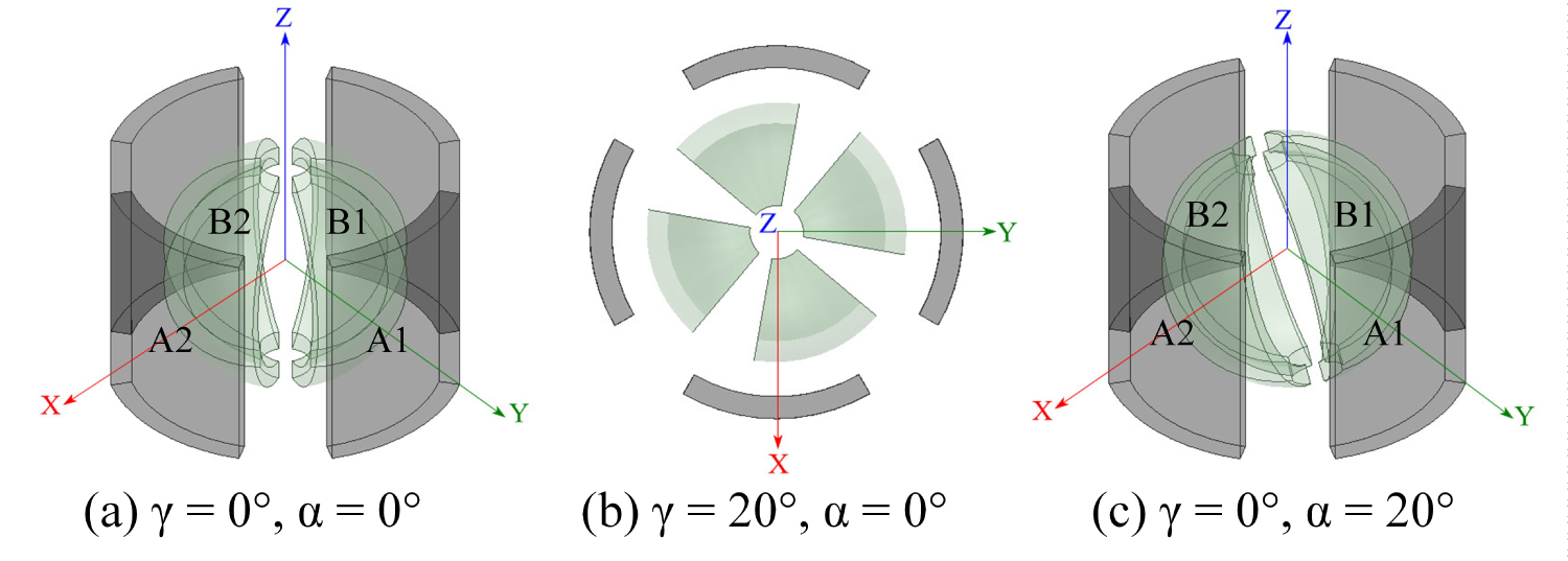
Figure 20: Physical model of the magnetostatic simulation....
Physical model of the magnetostatic simulation.
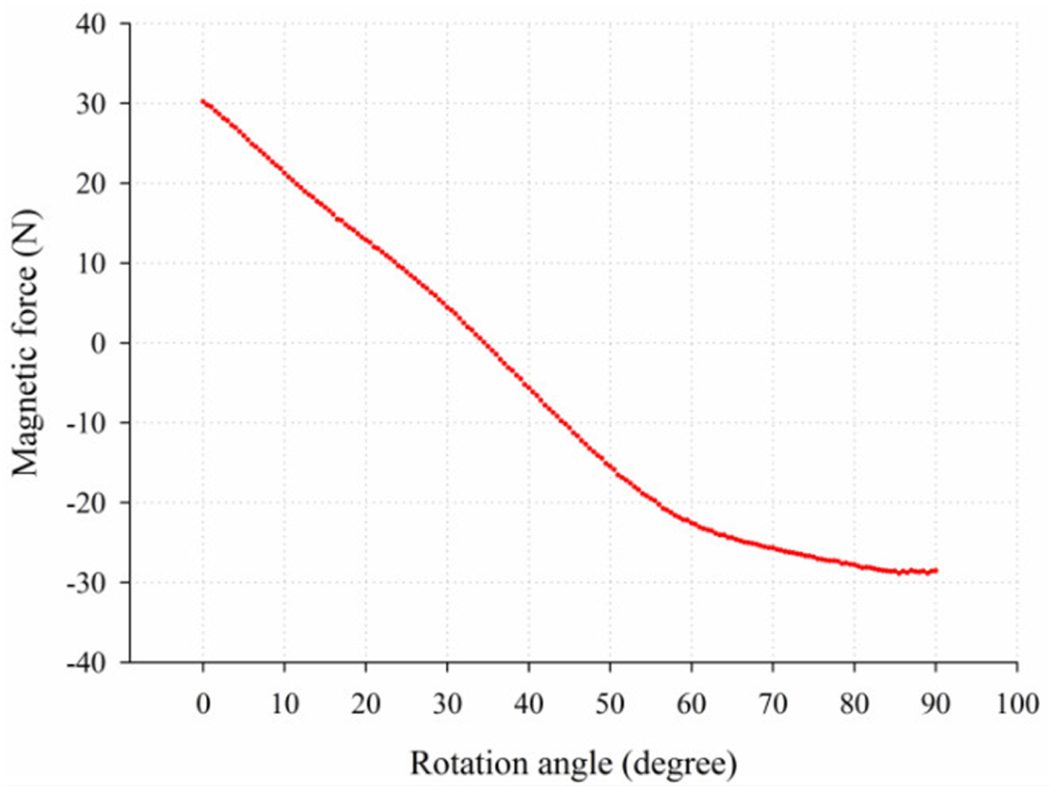
Figure 21: Relation between magnetic force of A1-B1 and...
Relation between magnetic force of A1-B1 and rotation angle γ.
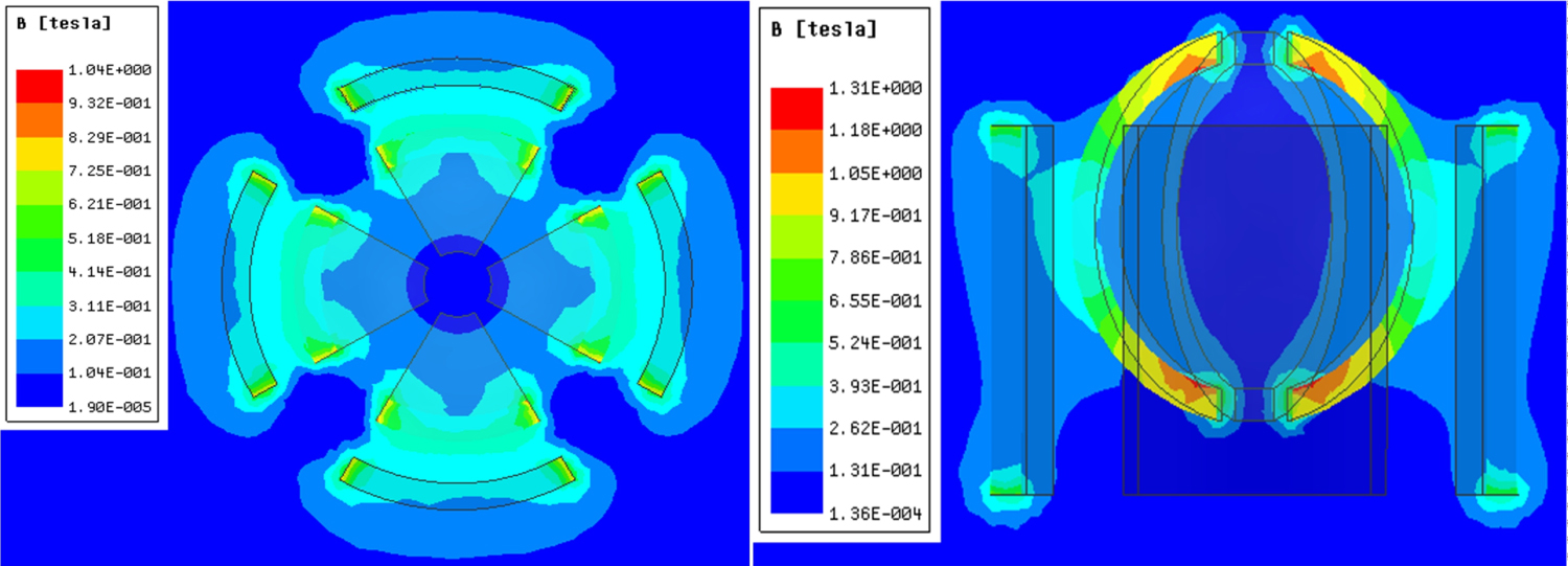
Figure 22: Magnetostatic simulation results....
Magnetostatic simulation results. (γ = 0°, α = 0°): a) Transverse cross-section; b) Longitudinal cross-section.

Figure 20: Magnetostatic simulation results...
Magnetostatic simulation results. (γ = 20°, α = 0°): a) Transverse cross-section; b) Longitudinal cross-section.
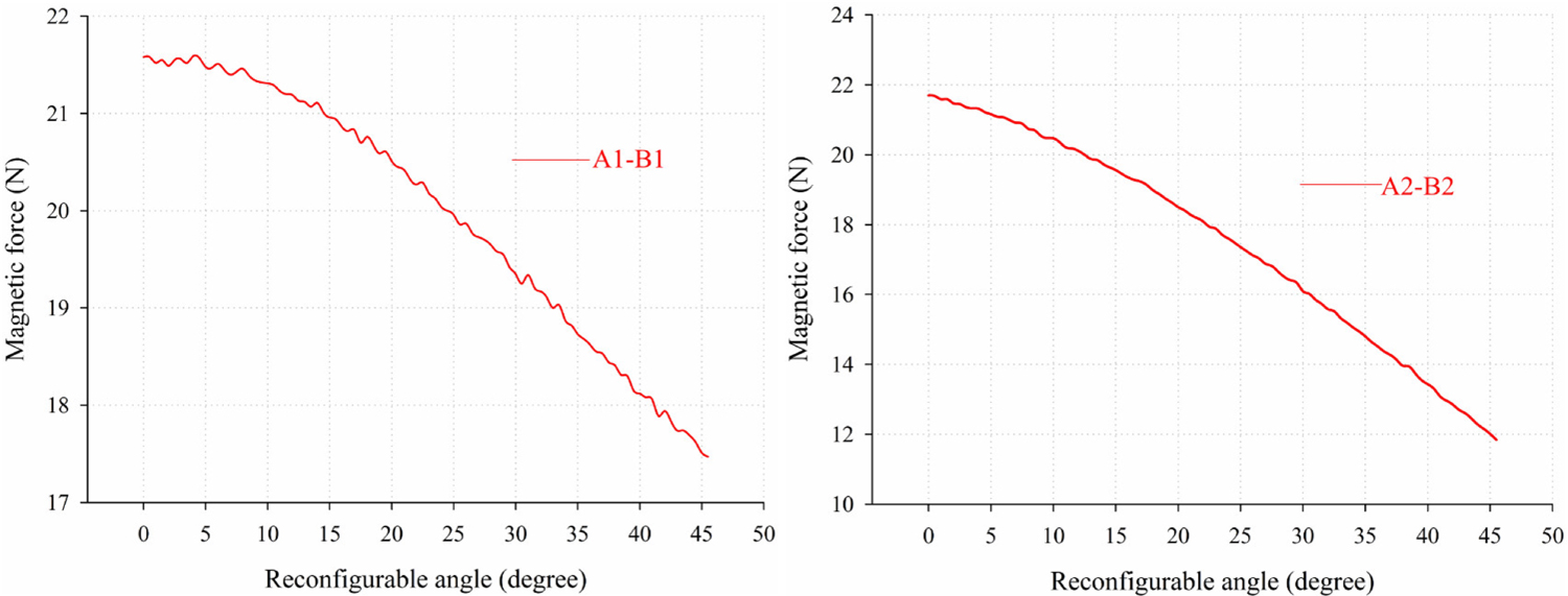
Figure 24: Relation between magnetic force and reconfigurable...
Relation between magnetic force and reconfigurable angle.
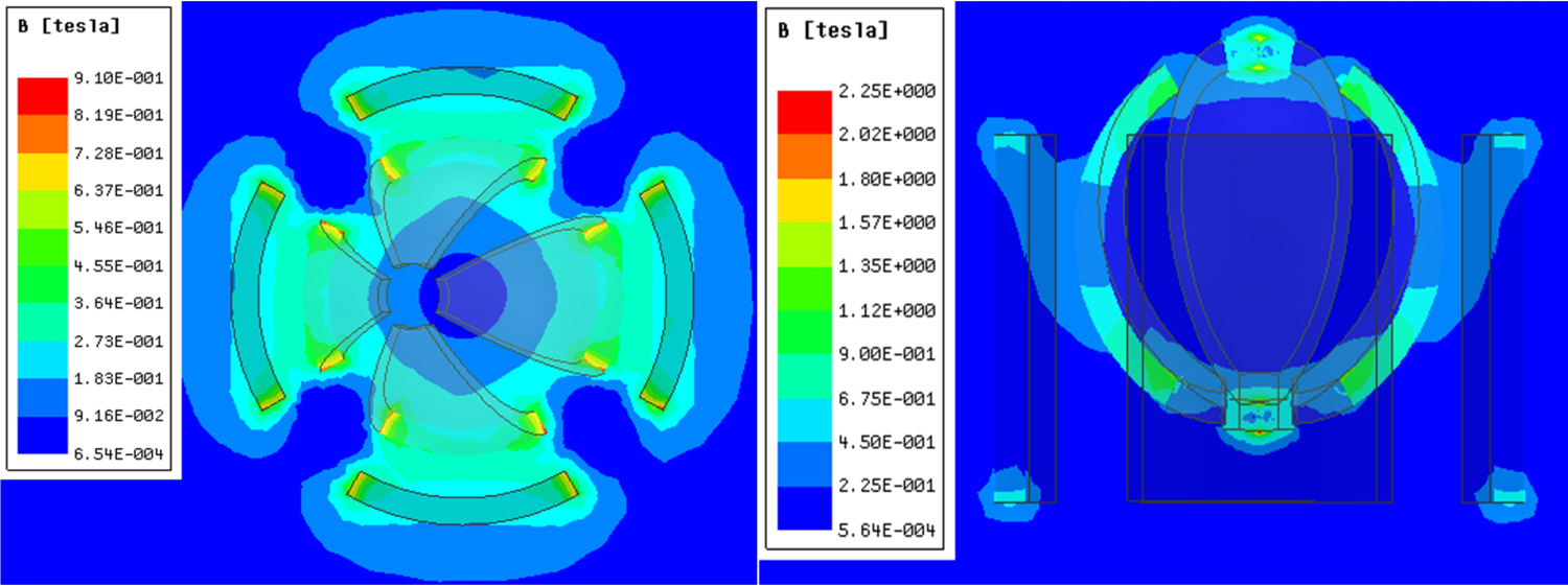
Figure 25: Magnetostatic simulation results...
Magnetostatic simulation results. (γ = 0°, α = 20°): a) Transverse cross-section; b) Longitudinal cross-section.
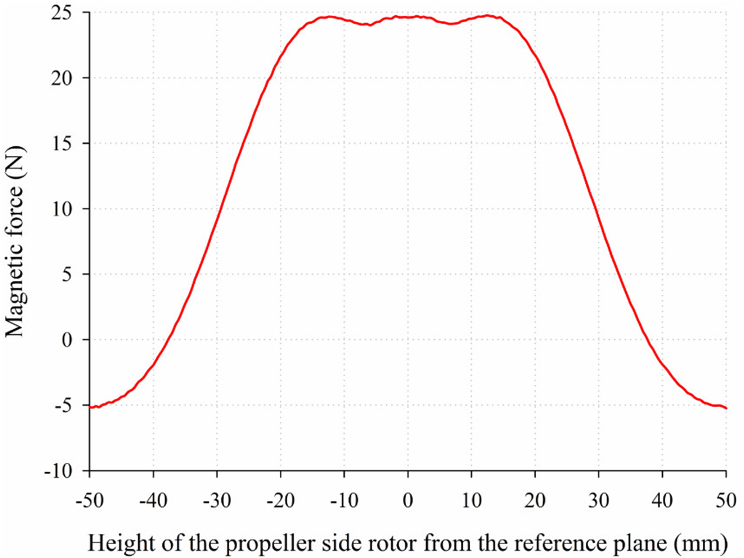
Figure 26: Relation between magnetic force and height...
Relation between magnetic force and height of the propeller side rotor.
References
- DR Blidberg, RM Turner, SG Chappell (1991) Autonomous underwater vehicles: Current activities and research opportunities. Robotics and Autonomous Systems 7: 139-150.
- Z Zeng, L Lian, K Sammut, F He, Y Tang, et al. (2015) A survey on path planning for persistent autonomy of autonomous underwater vehicles. Ocean Eng 110: 303-313.
- A Marino, G Antonelli (2015) Experiments on sampling/patrolling with two autonomous underwater vehicles. Robotics and Autonomous Systems 67: 61-71.
- M Jacobi (2015) Autonomous inspection of underwater structures. Robotics and Autonomous Systems 67: 80-86.
- A Sahoo, SK Dwivedy, PS Robi (2019) Advancements in the field of autonomous underwater vehicle. Ocean Eng 181: 145-160.
- O Chocron, H Mangel (2011) Models and simulations for reconfigurable magnetic-coupling thrusters technology. International Review on Modelling and Simulations 4: 325-334.
- O Chocron, H Mangel (2008) Reconfigurable magnetic-coupling thrusters for agile AUVs. Proceedings of IEEE/RSJ International Conference on Intelligent Robots and Systems (IROS) 3172-3177.
- EP Vega, O Chocron, JV Ferreira, M Benbouzid, PS Meirelles (2015) Evaluation of AUV fixed and vectorial propulsion systems with dynamic simulation and non-linear control. IECON 2015 - 41st Annual Conference of the IEEE Industrial Electronics Society 944-949.
- HF Gasparoto, O Chocron, M Benbouzid, PS Meirelles, LO Saraiva Ferreira (2019) Torque analysis of a flat reconfigurable magnetic coupling thruster for marine renewable energy systems maintenance AUVs. Energies 12: 56-72.
- O Chocron, EP Vega, M Benbouzid (2018) Dynamic reconfiguration of autonomous underwater vehicles propulsion system using genetic optimization. Ocean Eng 156: 564-579.
- A Hanai, K Rosa, SK Choi, J Yuh (2004) Experimental analysis and implementation of redundant thrusters for underwater robots. Proceedings of IEEE/RSJ International Conference on Intelligent Robots and Systems (IROS) 1109-1114.
- M Li, S Guo, H Hirata, H Ishihara (2015) Design and performance evaluation of an amphibious spherical robot. Robotics and Autonomous Systems 64: 21-34.
- Y Li, S Guo, Y Wang (2017) Design and characteristics evaluation of a novel spherical underwater robot. Robotics and Autonomous Systems 94: 61-74.
- X Hou, S Guo, L Shi, H Xing, Y Liu, et al. (2019) Hydrodynamic analysis-based modeling and experimental verification of a new water-jet thruster for an amphibious spherical robot. Sensors 19: 259.
- RAS Fernandez, EA Parrar, Z Milosevic, S Dominguez, C Rossi (2018) Design, modeling and control of a spherical autonomous underwater vehicle for mine exploration. Proceedings of IEEE/RSJ International Conference on Intelligent Robots and Systems (IROS) 1513-1519.
- J Villa, A Heininen, S Zavari, T Salomaa, O Usenius, et al. (2018) Mechanical subsystems integration and structural analysis for the autonomous underwater explorer. Proceedings of IEEE/RSJ International Conference on Intelligent Robots and Systems (IROS) 1488-1493.
- RAS Fernandez, EA Parrar, Z Milosevic, S Dominguez, C Rossi (2019) Nonlinear attitude control of a spherical underwater vehicle. Sensors 19: 1445.
- SA Watson, DJP Crutchley, PN Green (2011) The design and technical challenges of a micro-autonomous underwater vehicle (μAUV). Proceedings of IEEE International Conference on Mechatronics and Automation 567-572.
- A Mazumdar, HH Asada (2011) A compact underwater vehicle using high-bandwidth Coanda-effect valves for low speed precision maneuvering in cluttered environments. Proceedings of IEEE International Conference on Robotics and Automation (ICRA) 1544-1550.
- A Mazumdar, M Lozano, A Fittery, HH Asada (2012) A compact, maneuverable, underwater robot for direct inspection of nuclear power piping systems. Proceedings of IEEE International Conference on Robotics and Automation (ICRA) 2818-2823.
- A Mazumdar, A Fittery, W Ubellacker, HH Asada (2013) A ball-shaped underwater robot for direct inspection of nuclear reactors and other water-filled infrastructure. Proceedings of IEEE International Conference on Robotics and Automation (ICRA) 3415-3422.
- A Mazumdar, HH Asada (2013) Pulse width modulation of water jet propulsion systems using high-speed Coanda-effect valves. Journal of Dynamic Systems Measurement and Control 135: 051019.
- A Mazumdar, HH Asada (2014) Control-configured design of spheroidal, appendage-free, underwater vehicles. IEEE Transactions on Robotics 30: 448-460.
- A Mazumdar, MY Chuah, MS Triantafyllou, HH Asada (2014) Design for precision multi-directional maneuverability: Egg-shaped underwater robots for infrastructure inspection. IEEE International Conference on Robotics and Automation (ICRA) 2950-2956.
- A Mazumdar, MS Triantafyllou, HH Asada (2015) Dynamic analysis and design of spheroidal underwater robots for precision multidirectional maneuvering. IEEE/ASME Transactions on Mechatronics 20: 2890-2902.
- O Chocron, U Prieur, L Pino (2014) A validated feasibility prototype for AUV reconfigurable magnetic coupling thruster. IEEE/ASME Transactions on Mechatronics 19: 642-650.
- EP Vega, O Chocron, M Benbouzid (2016) A flat design and a validated model for an AUV reconfigurable magnetic coupling thruster. IEEE/ASME Transactions on Mechatronics 21: 2892-2901.
- HF Gasparoto, O Chocron, M Benbouzid, PS Meirelles (2017) Magnetic design and analysis of a radial reconfigurable magnetic coupling thruster for vectorial AUV propulsion. IECON 2017-43rd Annual Conference of the IEEE Industrial Electronics Society 2876-2881.
- J Sherman, RE Davis, WB Owens, J Valdes (2001) The autonomous underwater glider "Spray". IEEE Journal of Oceanic Engineering 26: 437-446.
- C Bourque, BG Newman (1960) Reattachment of a two-dimensional, incompressible jet to an adjacent flat plate. The Aeronautical Quarterly 11: 201-232.
- H Schlichting, K Gersten (1955) Boundary-layer theory. Pergamon.
Author Details
Yaxin Li*, Chuan Tian, Yu Wang, Peng Gao and Xinyu Ma
School of Electrical Engineering and Information, Southwest Petroleum University, Sichuan, China
Corresponding author
Yaxin Li, Associate Professor, School of Electrical Engineering and Information, Southwest Petroleum University, No.8 Xindu Avenue, Xindu District, 610500, Chengdu City, Sichuan, China.
Accepted: November 23, 2019 | Published Online: November 25, 2019
Citation: Li Y, Tian C, Wang Y, Gao P, Ma X (2019) Design and Simulation of a Collaborative Propulsion System for the Underwater Robot. Int J Robot Eng 4:019.
Copyright: © 2019 Li Y, et al. This is an open-access article distributed under the terms of the Creative Commons Attribution License, which permits unrestricted use, distribution, and reproduction in any medium, provided the original author and source are credited.
Abstract
The design of propulsion system is a very critical task because it determines the performance of underwater robots, such as maneuverability and endurance and so on. Generally, it is a challenge to develop a propulsion system which can make tradeoff among multiple degree-of-freedom (DOF) motions, simple and compact structure and low power consumption. Thus, we are motivated to propose a collaborative propulsion system for the underwater robot and its unique reconfigurable structure makes vectorial propulsion possible. The novel collaborative propulsion system consists of a Coanda effect based primary system and a magnetic coupling based auxiliary system. Based on Coanda effect, the primary system can provide sufficient thrust in four directions by only one water-jet. Meanwhile, as the assistance of the primary thruster, the auxiliary system can realize omnidirectional thrust to balance the robot whole body and meet the high requirement of maneuverability. In this paper, we present the mechanical structure of the propulsion system in detail and explain specific design of the fluidic valve by theoretical analysis. To evaluate the performance, simulations about jet attachment effect and magnetic coupling characteristic have been conducted at last so as to lay a solid foundation for the feasibility of such novel propulsion system.
Keywords
Vectorial propulsion, Collaborative propulsion system, Coanda effect, Magnetic coupling
Introduction
Nowadays, people pay more attention to exploring abundant marine resources while facing worldwide energy shortage issues. With the rapid development of technology, underwater robots play significant roles in ocean resource exploitation. Especially in some human inaccessible or hazardous areas, autonomous underwater vehicles (AUVs) are capable of sensing surroundings and navigating themselves to perform specific tasks, such as underwater structure inspection, marine resource exploration, marine environment monitoring [1-5]. However, these applications require AUVs with high maneuverability and reliable power supply. Thus, the propulsion system design is a key part for underwater robots development [6,7].
As far as most available AUVs, propulsion systems can be classified into three kinds: Propeller propulsion, biomimetic propulsion and vectorial propulsion [8,9]. In this paper, our team focuses on vectorial propulsion system because it outperforms the others in excellent steering ability. The fixed thruster design is a kind of classic vectorial propulsion system that combines thrusters on different orientations together to achieve vectorial propulsion [10,11]. But it has difficulty in motor waterproof and propeller reorientation issues. In order to adjust thrust in multiple planes, several servomotors were used to change the nozzle direction of water-jet thruster [12-14], but such complex mechanical structure resulted in massive volume and it was still impossible to realize continuous thrust orientation in limited space. In [15-17], another multiple propellers equipped symmetrical structure was developed so as to adjust the attitude of underwater robots effectively. To pursue high maneuverability, researchers proposed to mount six propellers around the equator of AUV's hull to achieve vectorial propulsion at the cost of complex control strategy [18]. In a word, high power consumption is an inevitable issue for above fixed thruster designs.
On the contrary, due to unique mechanical design, reconfigurable thrusters as another vectorial propulsion system are able to realize maneuverability and reduce weight and power consumption of underwater robots at the same time. By taking advantage of reconfigurable thrusters the research group of MIT was inspired by Coanda effect and presented a compact underwater vehicle utilizing high-bandwidth fluidic valves [19]. These valves enhanced dynamic performance in switching jet direction, but the jet device was still expected to get further improvement. A new water jet propulsion system using fluidic valves coupled with centrifugal pumps was developed for precision maneuvering [20]. In [21], researchers proposed a spherical underwater robot equipped with a single bidirectional centrifugal pump and two fluidic valves. Due to its compact structure and high performance, the fluidic valve can be treated as an attractive alternative with respect to conventional pumps and servomotors combined thrusters. However, the oscillation caused by the valve pulse width modulation control may cause errors in the heading. An integrated high-speed valve switching and pump output control scheme were developed and corresponding control algorithms were proposed in [22]. Both pulse width and pulse height were controlled in a coordinated manner so that the oscillation due to the switching could be reduced. A propulsion system based on multi-axis jet thrusters could be sealed completely within a smooth vehicle shell [23]. Such robot was able to achieve multi-DOF motions with only two pumps, but it may result in unstable horizontal motions. In [24], the egg-shaped underwater robot could perform planar motions at various vehicle depths by a closed loop depth control system. An optimized body shape and thruster layout design for water-jet propulsion underwater robot was proposed to achieve precision multidirectional maneuverability [25]. Besides, magnetic coupling is another good option for vectorial propulsion due to non-contact power transmission. Chocron et al. proposed a novel reconfigurable magnetic coupling thruster (RMCT) with only one servomotor to adjust propeller direction [26]. Vega et al. presented a flat RMCT that controlled thrust vector to reorient propeller [27]. This thruster had a simple and compact mechanical structure but its propeller could only be adjusted in one dimension, which meant more actuators were needed for multi-DOF motions. Gasparoto et al. came up with a conceptual design of the radial reconfigurable magnetic coupling thruster (R-RMCT) [28]. This design could be a possible solution for AUV's vectorial propulsion, but it had not yet been physically verified.
By contrast with various vectorial propulsion systems above, we are motivated to design a new generation of reconfigurable thrusters, which should make appropriate tradeoff among maneuverability, mechanical structure complexity, waterproof, stable performance and so on. In this paper, we propose a novel collaborative propulsion system for the underwater robot, which consists of a Coanda effect based primary propulsion system and a magnetic coupling based auxiliary propulsion system. As the primary propulsion system should provide sufficient thrust for the underwater robot, the jet steering control valve has been designed and the corresponding theoretical analyses about jet attachment have been carried out to demonstrate the reasonable mechanical structure. To support the primary propulsion system, the auxiliary one equipped with the reconfigurable magnetic coupling (RMC) device is responsible for omnidirectional thrust. At last, simulations have been conducted to demonstrate the feasibility of this novel propulsion system design.
The paper is organized as follows. In Section 2, we first present an overview of the collaborative vectorial propulsion system for the underwater robot and then explain the mechanical structure design of each system in detail. Then, we carry out the simulations to evaluate the jet attachment effect and explore the magnetic coupling behavior in Section 3. At last, Section 4 summarizes the paper and discusses the future work.
Mechanical Design
Overview of the underwater robot structure design
With the consideration of water resistance, underwater robots are usually designed to be streamlined. As shown in Figure 1, ellipse, slocum, spray and glider are four kinds of typical streamlines [29]. Our team developed the spray-shaped underwater robot that looks like a torpedo because it has a comparatively small drag coefficient [29], as depicted in Table 1.
Figure 2 displays the conceptual design of our developed underwater robot which is equipped with the novel collaborative propulsion system. Such newly designed system aims to achieve vectorial propulsion by the Coanda effect based primary system and the RMC based auxiliary system. In order to provide enough thrust for the underwater robot, the primary propulsion system is mounted at the tail cabin, and it can achieve multi-DOF motions by Coanda effect at the same time. However, such arrangement leads to an instable attitude issue because the primary propulsion system at the tail will change the position of robot barycenter, similar to a lever pivot. Therefore, a couple of auxiliary propulsion systems are necessary to balance the robot whole body. As depicted in Figure 2, two auxiliary propulsion systems based on the RMC are fixed at the middle cabin symmetrically as two wings. In this way, the auxiliary propulsion system can assist the primary one to meet the requirement of flexible steering capability.
The Coanda effect based primary propulsion system
The structure and working principle of primary propulsion system: As shown in Figure 3, the primary propulsion system is designed and implemented based on the Coanda effect. In the system, the core component Coanda jet device (CJD) utilizes control ring and fluidic valve together to realize multi-DOF motions. To explain how the CJD generates vectorial thrust by Coanda effect, we take a two-exit CJD schematic for example. As Figure 4 exhibits, the open and closed states of control ports C1 and C2 have close relationship with the jet exit directions. If left port C1 is opened to ambient and right port C2 is closed, the differential pressure of jet's two sides will increase gradually according to Bernoulli equation. When differential pressure reaches the threshold, the jet will bend to the right wall and attach to it steadily. Meanwhile, the high-speed jet will exit through exit 2 which just opposes the side of open control port C1. In brief, through switching the open or closed state of control ports, the vectorial propulsion will be realized by the Coanda effect. Therefore, in order to achieve multi-DOF motions, it is essential to design a unique jet steering control valve which is able to trigger jet attachment in any direction of four exits.
In this paper, we propose an innovative jet steering control valve and it is responsible for changing the water jet direction. Its two-dimensional schematic is shown in Figure 5. The outer ring with four ports is referred to control ring of CJD and set outside the neck of fluidic valve, which is called the inner ring and has four control ports as well. The four control ports of the inner ring are orthogonal to each other in comparison with the nonuniform ports distribution of outer ring. When the ports of both the inner ring and outer ring happen to meet each other like Figure 5a, the left side control ports start to open. If a servomotor drives the outer ring to rotate 18 degrees in counter-clockwise by a belt, the control port on the right side will open. According to Coanda effect, the jet will be ejected from the fluidic valve left exit, and the yaw motion of the underwater robot will be realized. In the same way, it is convenient to steer the underwater robot to move in pitch motion by switching the outer ring carefully in the place like Figure 5b. Especially, the jet will exit from all exits when the control ports of both outer and inner rings do not show coincident, as displayed in Figure 5c, the robot will gain speed in the surge direction. Additionally, the servomotor is chosen in this paper to change the control port states because it has an excellent performance in position control.
Analysis of jet attachment: As mentioned above, the control ports will determine the thrust direction of the Coanda effect based primary propulsion system, but whether such system can provide power effectively is related to the jet attachment. Therefore, it is necessary to explore how the fluidic valve structure affects the jet attachment. Actually, few studies have done this analysis, especially in the area of the fluidic valve geometric model and its jet attachment performance. A good solution is to simplify the problem into two-dimension based on the Bourque and Newman hypotheses [30]:
i. The jet flow is in two-dimension and incompressible.
ii. The jet is momentum conservation.
iii. The velocity distribution on the vertical plane of reattaching streamline is similar to the two-dimensional turbulent free jet.
iv. The static pressure of reattaching streamline is equal to the atmospheric pressure.
v. The jet speed is equal to that of nozzle exit and jet momentum per unit length is , if , and b denote supply pressure, external pressure, and the width of the nozzle respectively.
vi. The pressure in the low-pressure vortex zone is same and the central streamline can be treated as an arc of radius R approximately. Based on above assumption, these parameters satisfy the equation .
Two-dimensional geometric model of fluidic valve is shown in Figure 6. M is the collision point between the central streamline and the sidewall. D denotes minimum distance of the sidewall from the nozzle edge. θ is the angle covers the central streamline of the jet impinging on the sidewall theoretically. α signifies the sidewall slope.
Based on hypotheses above, the basic equation of the attachment point model is obtained:
Where:
J indicates the momentum at the main jet exit, J1 represents the flow momentum proceeding downstream along the sidewall, J2 denotes the flow momentum returned within the low-pressure vortex region at the point M. u is the jet velocity, ρ denotes the fluid density, is the distance from the position where the velocity is zero to central streamline, represents the length of the vertical line from the point M to the reattaching streamline.
In Figure 6, with ACB as the control region, momentum equation of the fluid along the sidewall is provided by Eq.(3):
According to geometric relation from Figure 6, Eq.(4) is obtained:
Based on the hypothesis (vi), the following relation can be acquired:
Eq.(3), Eq.(4) and Eq.(5) are utilized to achieve the basic equation of the control surface model:
As discussed above, the difference between Eq. (1) and Eq.(6) is that the attachment point model does not give a thought to the differential pressure . While the control surface model considers the differential pressure, it does not think about the momentum .
The two-dimensional turbulent free jet equation can be extended to a finite nozzle width [31]:
Where, signifies the diffusion coefficient. s represents the arc length measured from the nozzle exit along the jet central streamline. s0 denotes the distance of the nozzle exit from the jet hypothetical origin.
The relation between R and b is given by [30]:
The relation between D and b is obtained:
The relation between xr and b can be acquired:
represents the value of jet attachment.
Based on above analysis, the jet attachment is greatly influenced by parameters such as α and D. If the slope is too large, the jet attachment is unstable, while it is hard to recovery the pressure and flow if slope is too small.
Due to the existence of D and the entrainment of the jet, wall attachment jet will generate a vortex at the low-pressure zone. When D increases, the vortex will become larger and increase differential pressure of jet's two sides, which enhances the stability of jet attachment. On the contrary, excessive vortex results in a comparatively large energy loss on the side of jet attachment. In summary, it is important to choose proper values of α and D so as to make fully use of fluidic valve inner cavity. It should be noted that above analytical results hold up under condition that values of D/b and α are comparatively large, otherwise it violates hypothesis (vi).
In the primary propulsion system, jet attachment caused by Coanda effect occurs in the fluidic valve of CJD. In other words, the structure of fluidic valve, especially the design of sidewall slope and wedge shape, has a great influence on jet attachment. According to empirical value, wedge shape is designed as a concave wedge. Our fluidic valve is displayed in Figure 7 with concave wedge and sidewall slope of 12 degrees.
Based on above analyses, Figure 8 presents the structure design of fluidic valve. Figure 9 pictures a prototype of the fluidic valve printed by 3D printer using ABS resin. The test shows that the fluidic valve is feasible to adjust the jet direction. In addition, a test platform based on underwater robot is being built and improved, as shown in Figure 10.
The RMC based auxiliary propulsion system
As the assistance of primary propulsion system, the auxiliary one exploits the RMC mechanical design to achieve vectorial propulsion. By taking advantage of magnetic transmission, the unique non-contact design does not only address the waterproof problem of driver motor, but also provide the omnidirectional thrust to cooperate with the primary system so as to keep the robot body balance. Next, we will describe the structure design and working principle of the RMC based auxiliary system in detail.
The auxiliary propulsion system, as depicted in Figure 11, is mainly composed of the vectorial steering actuator and the RMC based power transmission mechanism. To achieve the vectorial thrust output in the space, the steering actuator shown in Figure 12, is assembled by two arc-shaped sliding rails which intersect with each other.
At the end of each sliding rail, a servomotor is mounted on the support frame to change the deflection angle with 45 degrees at most. Such structure makes propeller, which locates at the intersection of two sliding rails, steer in omni-direction possible. As the propeller is rotated by the RMC based power transmission mechanism, a bearing is inserted just in the intersection of two sliding rails, which can stabilize the propeller shaft and reduce the friction between the propeller shaft and sliding rails at the same time. To adjust the propeller orientation, Figure 13 depicts two cases of arc-shaped sliding rails deflecting in different angles.
As the reconfigurable thruster, the auxiliary propulsion system requires the propeller shaft to deflect with the vectorial steering actuator. Therefore, the RMC based power transmission is a good choice because it outperforms other mechanical joints in the aspects of steering flexibility and non-contact property.
The magnetic coupling structure mainly consists of the motor side rotor and the propeller side rotor, which are designed as a hollow cylinder and a spherical shape respectively. Such structure allows the propeller side rotor to freely deflect inside the motor side rotor. As Figure 14 shows, four pieces of arc-shaped magnets are embedded on the spherical propeller side rotor with 30 degrees apart from each other. Outside the ball-shaped propeller side rotor, four pieces of curved magnets are symmetrically distributed in the grooves of motor side rotor with opposite polarity adjacent to each other. When the motor drives the motor side rotor to rotate, the propeller side rotor will follow its motion due to magnetic coupling. Besides, the propeller side rotor can deflect up to 45° driven by the vectorial steering actuator. By taking advantage of RMC, the auxiliary propulsion system can address the motor waterproof issue as well. Based on above discussion, Figure 15 depicts a prototype of the RMC based auxiliary propulsion system.
Simulations and Results
To evaluate performance of the collaborative propulsion system, it is necessary to conduct simulations about the Coanda effect based primary system and the RMC based auxiliary system. Before simulations, 3D model of the collaborative propulsion system was built in CATIA and then it was imported into ANSYS WORKBENCH for meshing. Simulations about internal flow field of the fluidic valve were carried out on ANSYS FLUENT. After that, we conducted magnetostatic simulations of the RMC on ANSYS MAXWELL to prove the reasonable design of auxiliary system. All simulations were run on workstation with 64 bits processor Intel(R) Xeon(R) CPU E5-2687W v4 @ 3.0 GHz, with 128 GB of RAM.
The simulation of fluidic valve
According to Coanda effect, the jet is supposed to deflect to corresponding exit when a certain control port was fully opened. It should be noted that we referred to the Coanda effect as the jet attachment effect in this paper. In internal flow field simulation, the inlet flow velocity V1 increased from 30 cm/s to 250 cm/s. To evaluate the efficiency of jet attachment in the fluidic valve, we defined a metric η which was the percentage of corresponding outlet flow to total flow of both inlet and control port. Figure 16 depicts the relationship between metric η and inlet flow velocity V1. A sharp rise appears when V1 is in the range of 43 cm/s to 45 cm/s because the low flow speed is not enough to cause the jet attachment effect. In particular, Figure 16 magnifies the range of inlet flow velocity V1 from 40 cm/s to 50 cm/s in detail. The curve in Figure 16 implies that there exists a limen for inlet flow velocity. If the inlet flow velocity is lower than limen, the jet attachment performance is comparatively poor. In other words, the jet attachment effect is able to change thrust orientation effectively of the primary propulsion system only when the inlet flow velocity exceeds 45 cm/s. Moreover, it should be noted that the efficiency η will be saturated if the flow velocity exceeds 250 cm/s.
Besides, to assess the jet attachment effect of fluidic valve from another point, several inlet flow velocity values were selected. Namely, the inlet flow velocity V1 increased from 40 cm/s to 250 cm/s. As shown in Figure 17, the effect of jet attachment becomes more obvious as inlet flow velocity V1 grows. The results suggest that it is necessary to control the water pump because high inlet flow velocity is inevitable to provide sufficient thrust. But when inlet flow velocity is higher than 250 cm/s, the jet attachment effect will begin to deteriorate. The reason is that excessive high flow velocity will result in growing jet inertia and it is hard to change the jet direction.
When inlet flow velocity is given, jet attachment of the fluidic valve is triggered by control port. Thus, we conducted simulations by varying control port flow velocity V2 and explored how V2 influenced the jet attachment effect. Based on the result in Figure 16, the jet attachment effect has a high efficiency when inlet flow velocity is over the limen 45 cm/s. In simulations, the inlet flow velocities are set to 50 cm/s, 100 cm/s, 150 cm/s and 200 cm/s, and Figure 18 presents the relation between jet attachment efficiency η and control port flow velocity V2 respectively. With the increase of control port flow velocity, there exists an optimal V2 for each inlet flow velocity to reach the maximal jet attachment efficiency η. Figure 19 exhibits the internal flow field simulation results when V1 is set to 150 cm/s, for example. It is obvious that the jet attachment effect is reinforced when V2 grows from 20 cm/s to 50 cm/s.
Magnetostatic analysis
To verify the reasonable design of RMC, the magnetostatic analysis was carried out. Due to symmetrically distributed magnets on both the motor side rotor and the propeller side rotor, two pairs of adjacent magnets labeled A1-B1 and A2-B2 were selected randomly for analysis. In the ANSYS MAXWELL simulation, the solver was set as magnetostatic and the material was neodymium magnet NdFe30. To describe the deflection of propeller side rotor conveniently, the coordinate frame is built in Figure 20a. γ was defined as the rotation angle at which the propeller side rotor rotated along the Z-axis. Since the vectorial propulsion required the steering actuator to deflect the propeller with the help of RMC, two deflection angles were needed which represented the propeller side rotor to rotate along both X-axis and Y-axis. We defined α as the angle (i.e., reconfigurable angle) of propeller side rotor deflecting along the Y-axis, for instance. Figure 20a plots the reference position where γ = 0°, α = 0°. When the propeller side rotor begins to rotate, Figure 20b is the moment when γ = 0°. Moreover, Figure 20c displays that the propeller side rotor is deflected 20 degrees by the vectorial steering actuator.
Next, the magnetostatic simulations were carried out by changing the rotation angle γ and reconfigurable angle α respectively. Figure 21 shows the relationship between the magnetic force of A1-B1 and the rotation angle γ. Intuitively, when γ = 0°, the magnets on both two rotors completely become face to face and magnetic attractive force reaches maximum, while magnetic repulsive force attains maximum when γ = 90°. Figure 22 displays the magnetic flux density in both transverse and longitudinal cross-sections when γ = 0°, α = 0°. The overlapping area of magnets decreases as the rotation angle increases, which results in the diminished magnetic force. Figure 23 exhibits the magnetic flux density when the rotation angle is 20 degrees without deflection. If the vectorial steering actuator drives the propeller side rotor to deflect along Y-axis, the magnetic force between A1-B1 and A2-B2 is depicted in Figure 24 respectively. For the same reason, the magnetic overlapping area decreases as the reconfigurable angle α increases. Figure 25 shows the magnetic flux density when γ = 0°, α = 20°.
Above simulations imply that the rotation and reconfigurable angles have great impact on magnetic coupling, so do the relative positions between two rotors. Hence, we investigated how the center position of propeller side rotor with respect to the reference plane influences magnetic force. Such reference plane was determined by two rotation axes of servomotors mounted on the vectorial steering actuator. Figure 26 describes the magnetic force with the offset of center position above or below the reference plane. The curve was nearly symmetric with the center located on plane. The positive offset signified the center above the reference plane and vice versa. According to such results, the maximal magnetic force was obtained at the offset above or below plane 15 mm but we dropped the negative one. The reason is that the bigger reconfigurable angle would be achieved if we chose the positive offset.
Discussion
In the propulsion system design, usually there are incompatible characteristics among maneuverability, motor waterproof, and vectorial thrust output. In this paper, we are inspired to propose a novel collaborative propulsion system, which comprises of the Coanda effect based primary system and the magnetic coupling principle based auxiliary system. Such primary-auxiliary propulsion system design, to our knowledge, is an original and innovative research when compared with most available studies. On the one hand, compared to conventional propulsion systems based on Coanda effect, our developed primary propulsion system is to achieve thrust output in four directions by one water-jet, which reduces the complexity of propulsion system structure design and the energy consumption of the underwater robot effectively. On the other hand, the auxiliary propulsion system is able to realize omnidirectional thrust by the vectorial steering actuator. Meanwhile, motor side rotor and propeller side rotor can be sealed completely and separately by non-contact power transmission, which addresses the problem of motor waterproof successfully.
In the simulation of fluidic valve, the effect of jet attachment is gradually improved as inlet flow velocity grows within a certain range. While the effect of jet attachment begin to deteriorate when the inlet flow velocity exceeds the thresholds at both ends. Besides, with the increase of control port flow velocity, the effect of jet attachment first gradually improves and then begins to decline. In terms of the auxiliary propulsion system, to make the propeller side rotor better match the motor side rotor and reduce the loss of motion between rotors as much as possible, the motor side rotor and the propeller side rotor are designed as hollow cylinder and spherical shape respectively. The position of propeller side rotor is set at the offset above reference plane 15 mm so as to achieve maximal magnetic force and reconfigurable angle. In summary, the collaborative propulsion system plays an important role in thrust supply and vectorial steering simultaneously, which makes an appropriate tradeoff among mechanical structure, energy consumption and omnidirectional thrust output.
Conclusion
The design of propulsion system, as a key part of underwater robots development, plays an important role in performance such as maneuverability, endurance and so on. Comparing pros and cons of previous work, we are motivated to propose a collaborative propulsion system which aims to realize reconfigurable vectorial propulsion. Such propulsion system consists of primary one and auxiliary one, which is mounted on the torpedo-shaped underwater robot. The primary system as the main thruster is assembled at the tail and auxiliary system is fixed at the middle cabin to balance the robot whole body. By taking advantage of Coanda effect, the primary system can not only provide sufficient power for the robot but also realize multi-DOF motions. Meanwhile, the magnetic coupling based auxiliary system can assist the primary one to realize flexible steering capability. To evaluate the performance of our developed collaborative propulsion system, a series of simulations about internal flow field and magnetostatic have been carried out. The results demonstrate the feasibility and rationality of our developed propulsion system.
Based on above work, we are well prepared to assemble the whole underwater robot by fabricating the prototype of the fluidic valve and the RMCT. Future work will focus on control and optimization of collaborative propulsion system equipped underwater robot.
Acknowledgment
This research is supported by Young scholars development fund of SWPU (201699010118).