
International Journal of Astronautics and Aeronautical Engineering
(ISSN: 2631-5009)
Volume 3, Issue 2
Research Article
DOI: 10.35840/2631-5009/7517

Article Formats
An Assessment of a Linear Aerodynamic Modeling of a Generic Flapping Wing Ornithopter
Table of Content
Figures
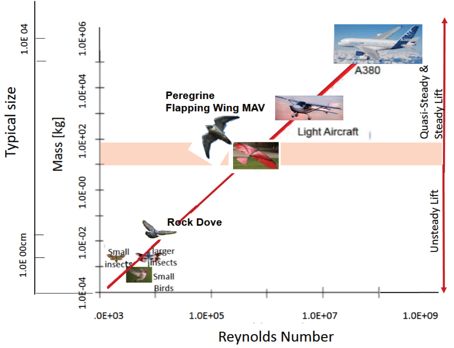
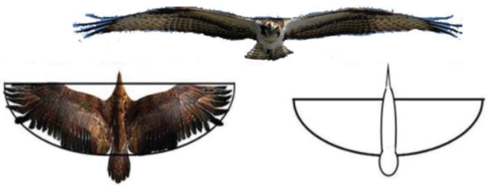
Figure 2: A generic semi-elliptical...
A generic semi-elliptical ornithopter wing planform adopted from eagle-wing planform. Top: Frontal view of an eagle; Left: Top view; Right: Baseline model.
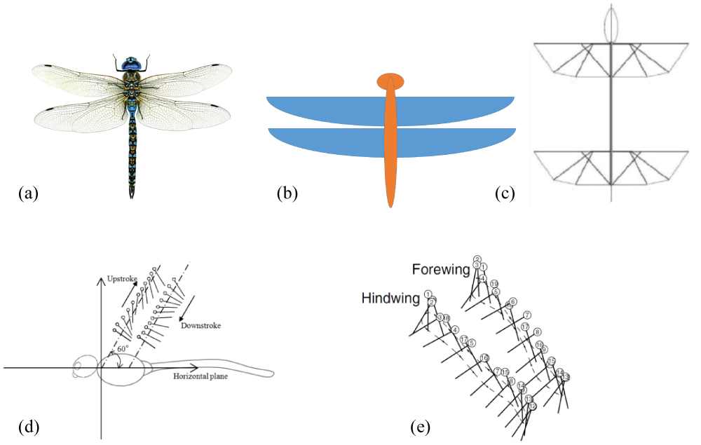
Figure 3: a) Dragon fly as a quad-wing...
a) Dragon fly as a quad-wing ornithopter; b) A Computational model for a quad-wing ornithopter; c) Proposed experimental model for a quad-wing ornithopter; d,e) Upstroke and downstroke motion of a dragonfly [3].
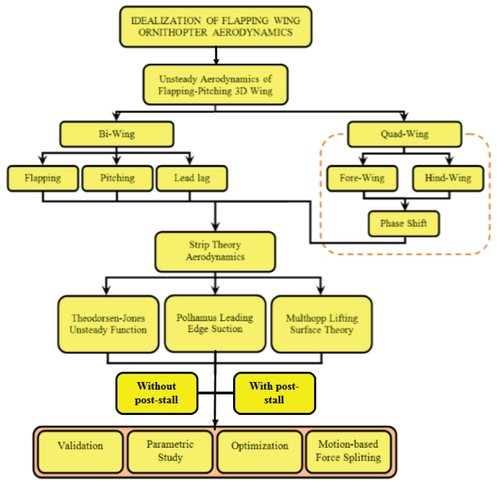
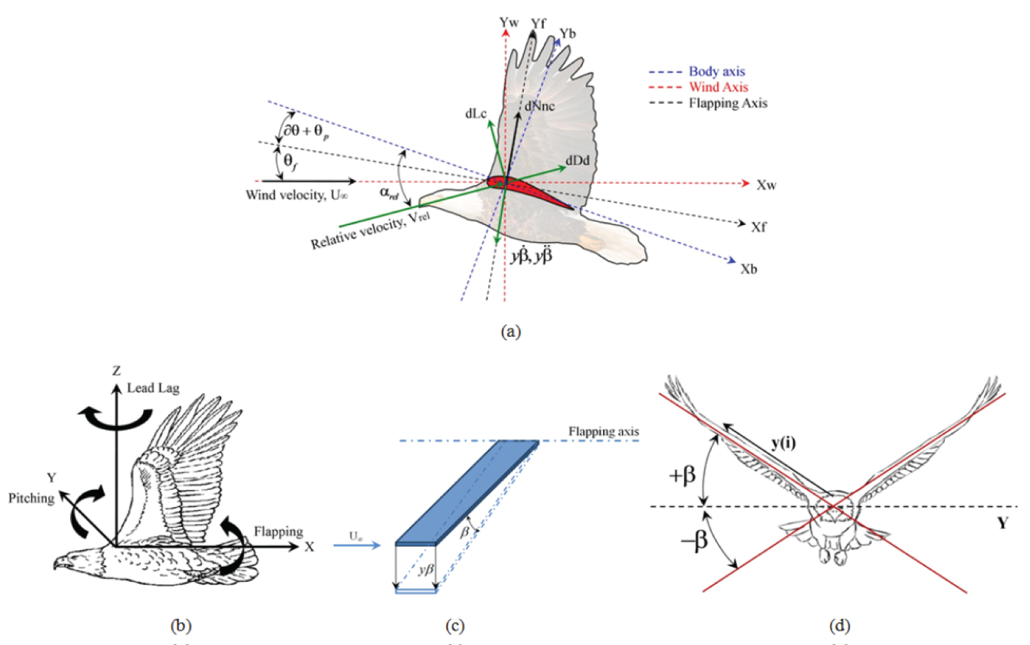
Figure 5: a) System of forces on a...
a) System of forces on a wing section; b) Flapping, Pitching and Lead-lag motion and axes; c, d) β angle of the flapping motion of the flapping wing.

Figure 6: Schematic diagram of flapping...
Schematic diagram of flapping and pitching components of induced velocities at ¾ chord.
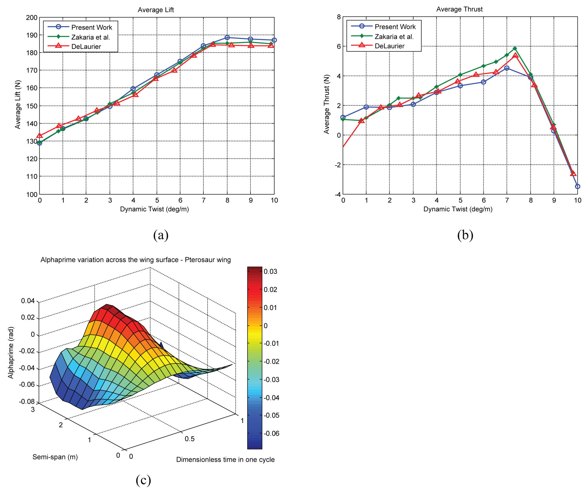
Figure 7: Verification of aerodynamic...
Verification of aerodynamic modelling of present work with work by DeLaurier [2] and Zakaria, et al. [29]: a) Average lift per cycle; b) Average thrust per cycle; c) Distribution of α' across the Pterosaur model wing.
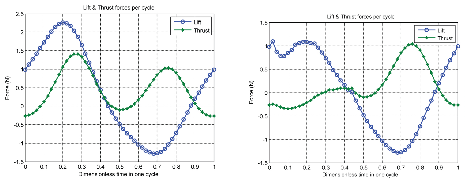
Figure 8: Left: Lift and thrust for...
Left: Lift and thrust for bi-wing ornithopter (without stall condition); Right: Lift and thrust for bi-wing ornithopter (with stall condition).
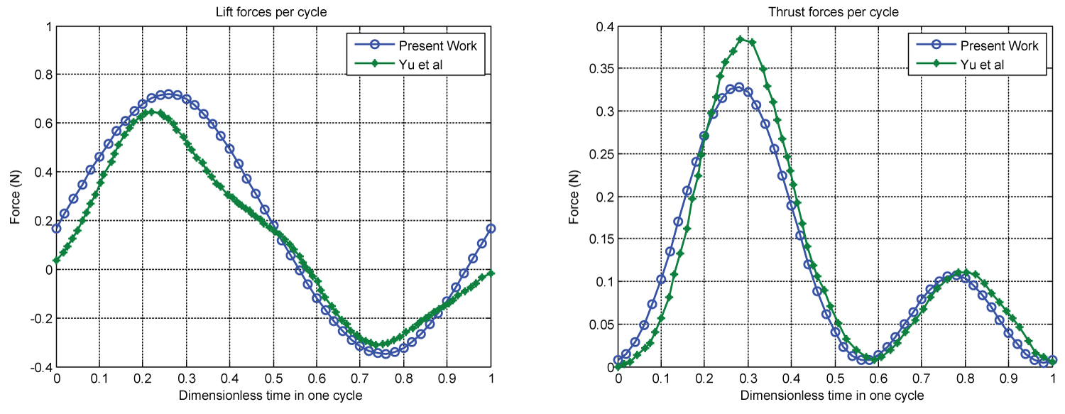
Figure 9: Comparison of the results...
Comparison of the results obtained by the present scheme with the three-dimensional unsteady vortex lattice method of Yu, et al. [30] for similar wing geometry.
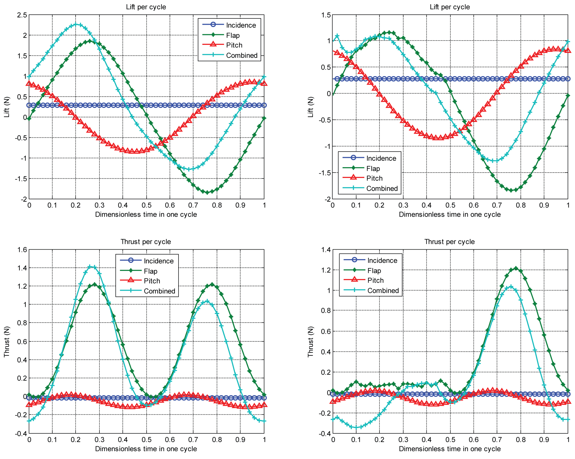
Figure 10: The influence of individual...
The influence of individual contributions of the pitching-flapping motion and incidence angle on the flight performance; Top: Lift without stall (left) and lift with stall (right); Bottom: Thrust without stall (left) and thrust with stall (right).
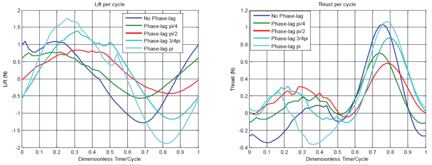
Figure 11: Variation of lift and thrust...
Variation of lift and thrust with phase lag between pitching and flapping.
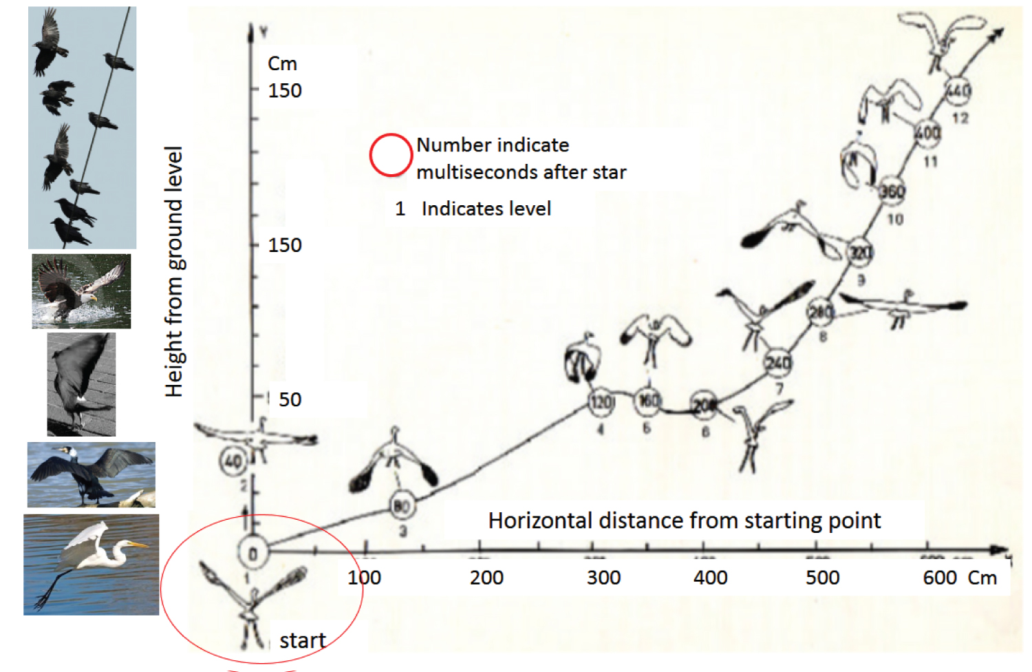
Figure 12: The flight stages of an egret...
The flight stages of an egret (extended from Dhawan); the start phase is encircled in a red ellipse. Other examples are illustrated by several figures for other birds at the left.
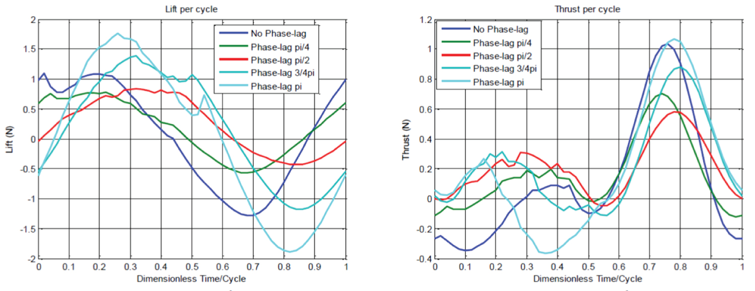
Figure 13: a) Lift; b) Thrust for...
a) Lift; b) Thrust for bi-wing ornithopter for each kinematics definition (pitch articulation with respect to flapping motion).

Figure 14: a) Drag producing vortex street...
a) Drag producing vortex street; b) Thrust producing vortex street (Platzer [34]).
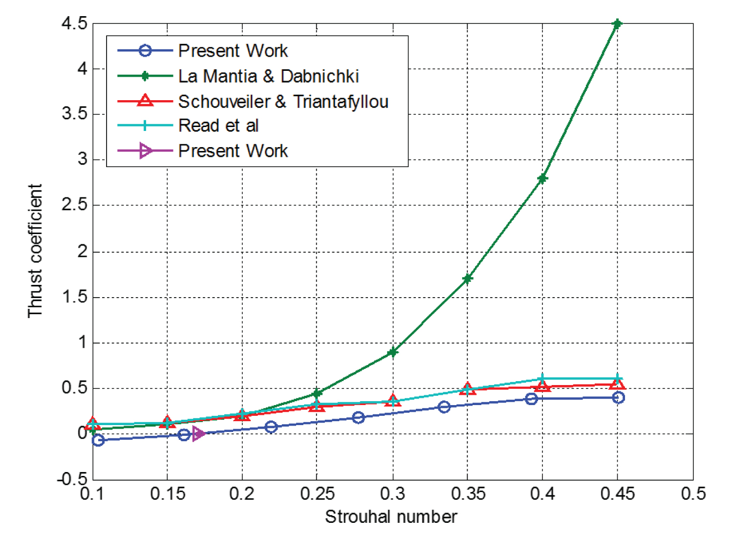
Figure 15: Strouhal Number of present...
Strouhal Number of present work in comparison with other results from the selected literatures [39-41]. In the comparison, rectangular wing planform with pitching oscillation is utilized.
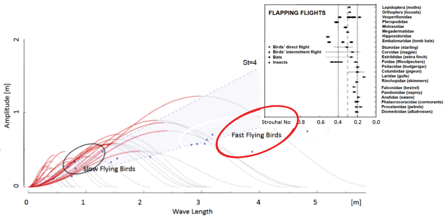
Figure 16: Flight regimes for different...
Flight regimes for different natural flyers presented as Amplitude versus Wavelength (Corum [42] and Taylor, et al. [36]).
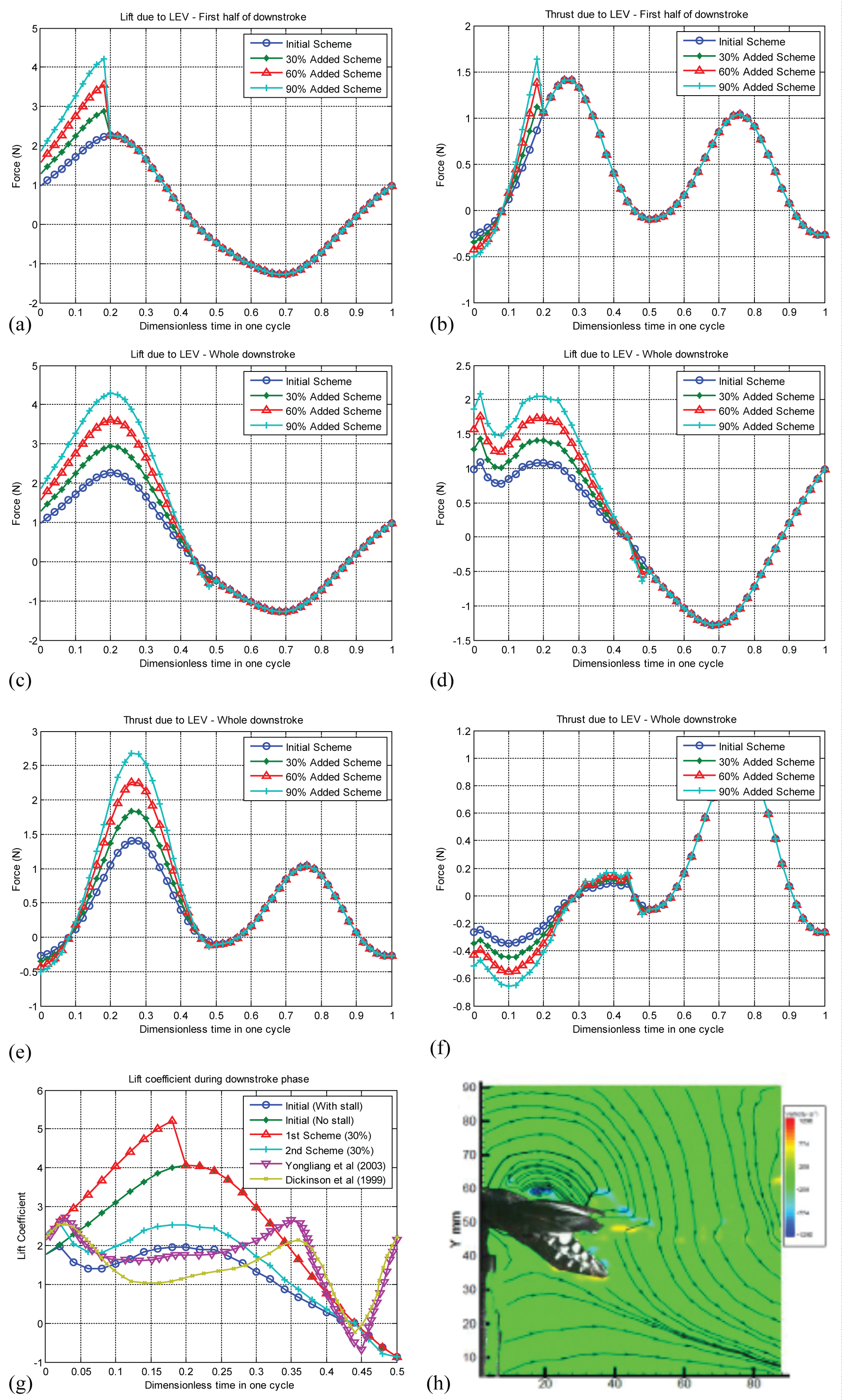
Figure 17: Results from the heuristic...
Results from the heuristic LEV Modeling; a) The effect of simulated LEV during the first half of the downstroke on Lift for cosinusoidal motion; b) The effect of simulated LEV during the first half of the downstroke on thrust for cosinusoidal motion; c,d) The effect of simulated LEV during the entire downstroke on Lift for cosinusoidal motion (left c)-without stall, right d)-with stall); e,f) The effect of simulated LEV during the entire downstroke on Thrust for cosinusoidal motion (left e)-without stall, right f)-with stall); g) Results from Yu, et al. [48] and Dickinson, et al. [10] are shown here for qualitative comparison of lift coefficient during the downstroke phase; h) Leading edge vortex induced flow field above the wing of hawkmoth as obtained by Bomphrey, et al. (reproduced from [46], with permission) which represent one of possible flow-field pattern above the wing.
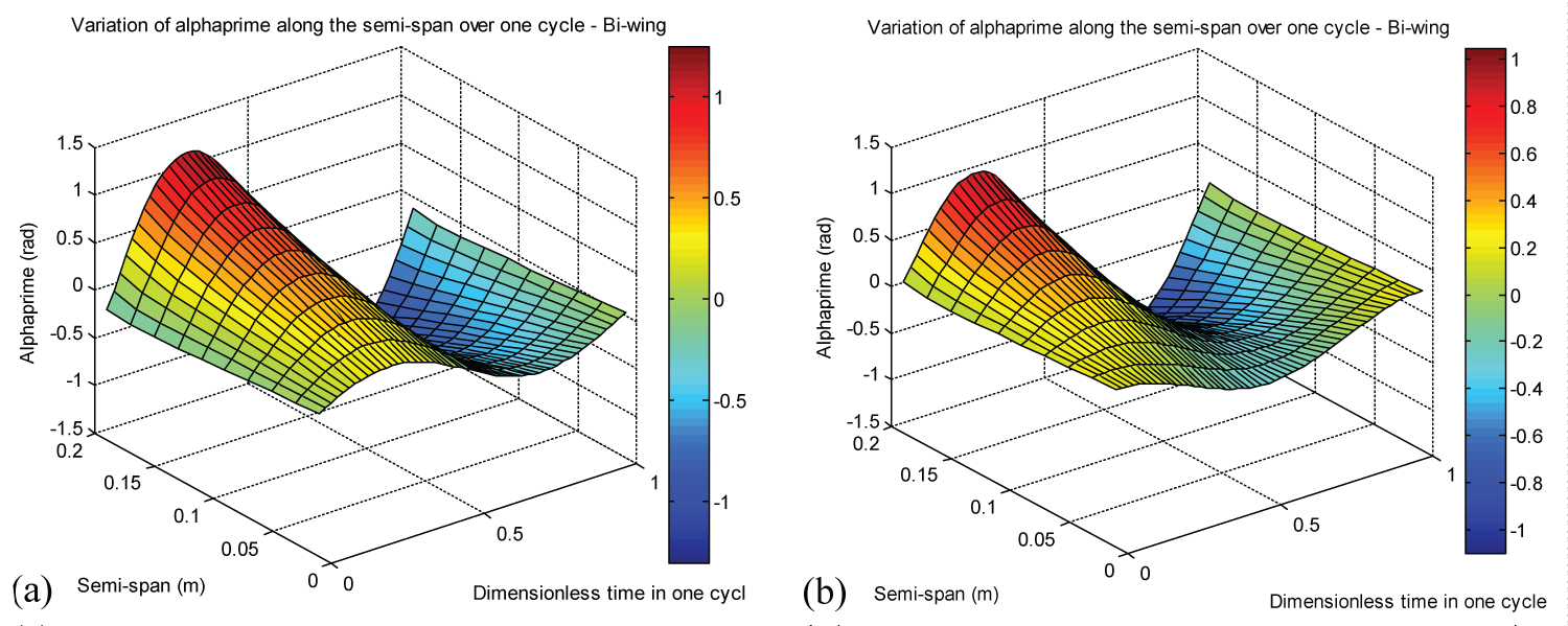
Figure 18: a) α', baseline motion...
a) α', baseline motion (no LEV), sinusoidal pitch; b) α', baseline motion (no LEV), cosinusoidal pitch for the heuristic modeling shown in Figure 17.
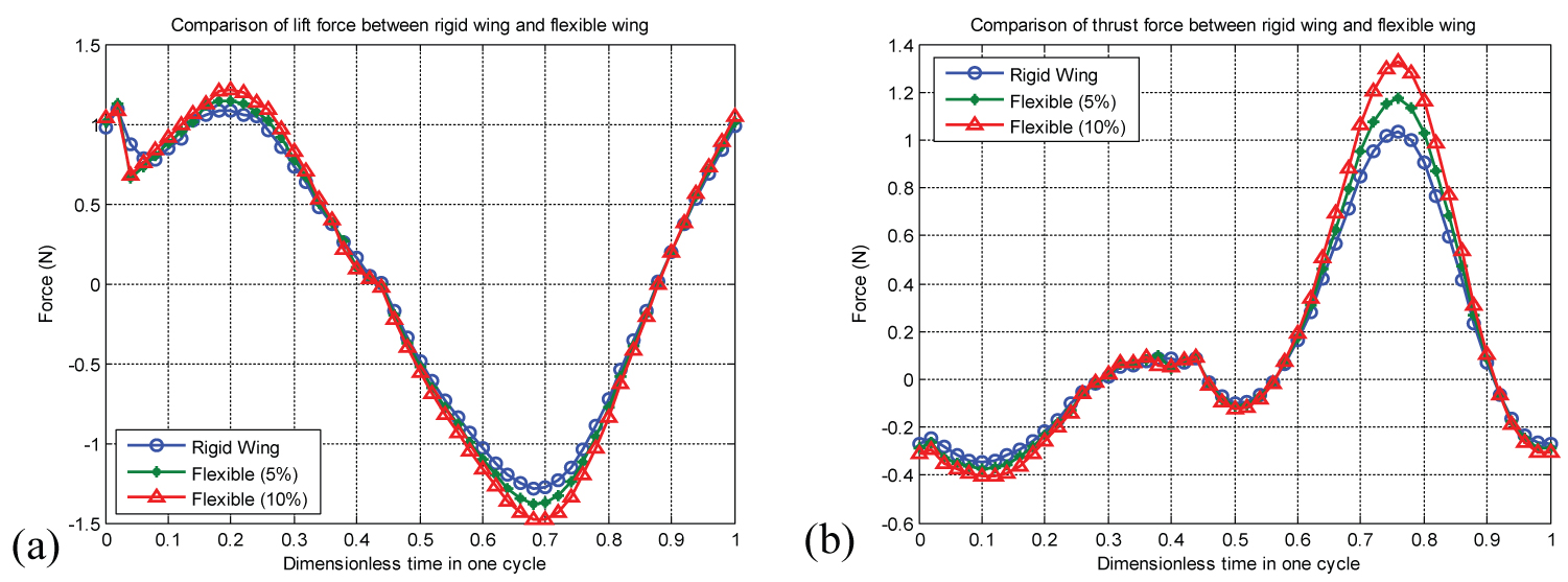
Figure 19: a) Lift; b) Thrust variation...
a) Lift; b) Thrust variation with rigid wing and flexible wing of 5% and 10% using heuristic model.
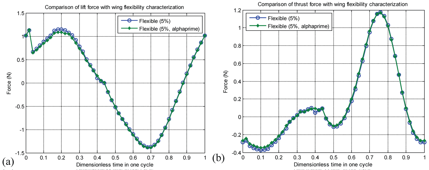
Figure 20: a) Lift; b) Thrust variation...
a) Lift; b) Thrust variation with flexible wing of 5% and 5% from alphaprime (α').
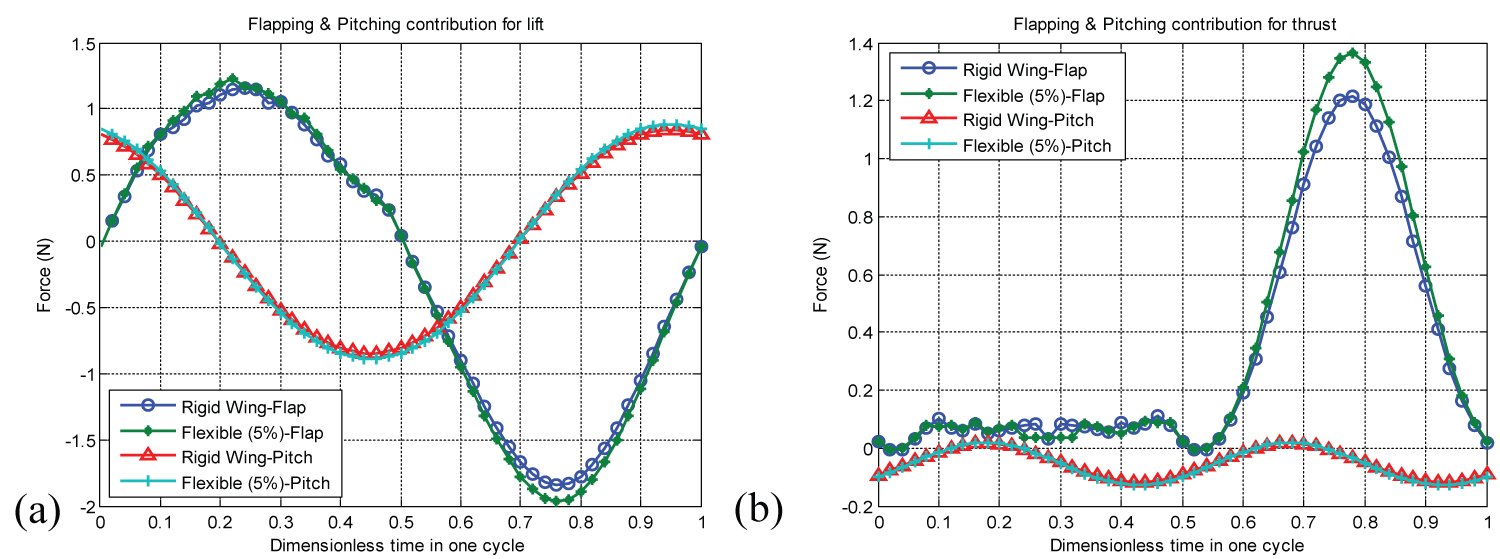
Figure 21: Contribution of flapping...
Contribution of flapping and pitching motion individually on a) Lift; (b) Thrust forces for rigid wing and flexible wing of 5%.
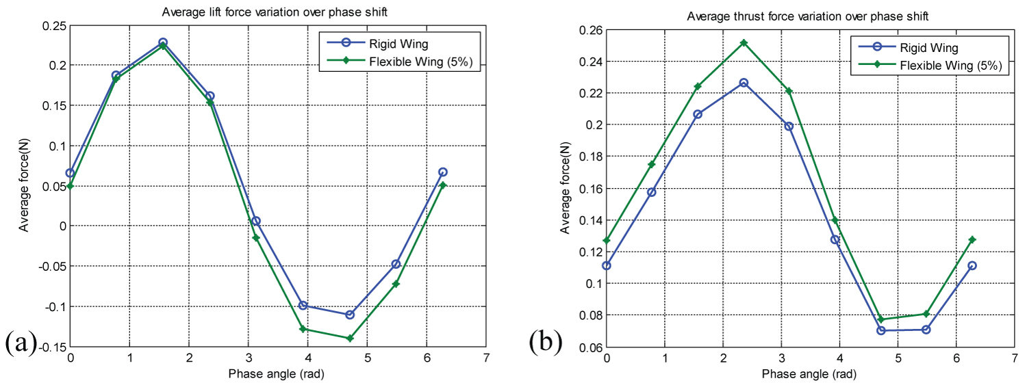
Figure 22: Phase shift influence...
Phase shift influence on a) Lift; b) thrust forces for rigid wing and flexible wing of 5%.

Figure 23: Schematic diagram of the...
Schematic diagram of the fore wing downwash and the induced angle of attack on the hind wing.
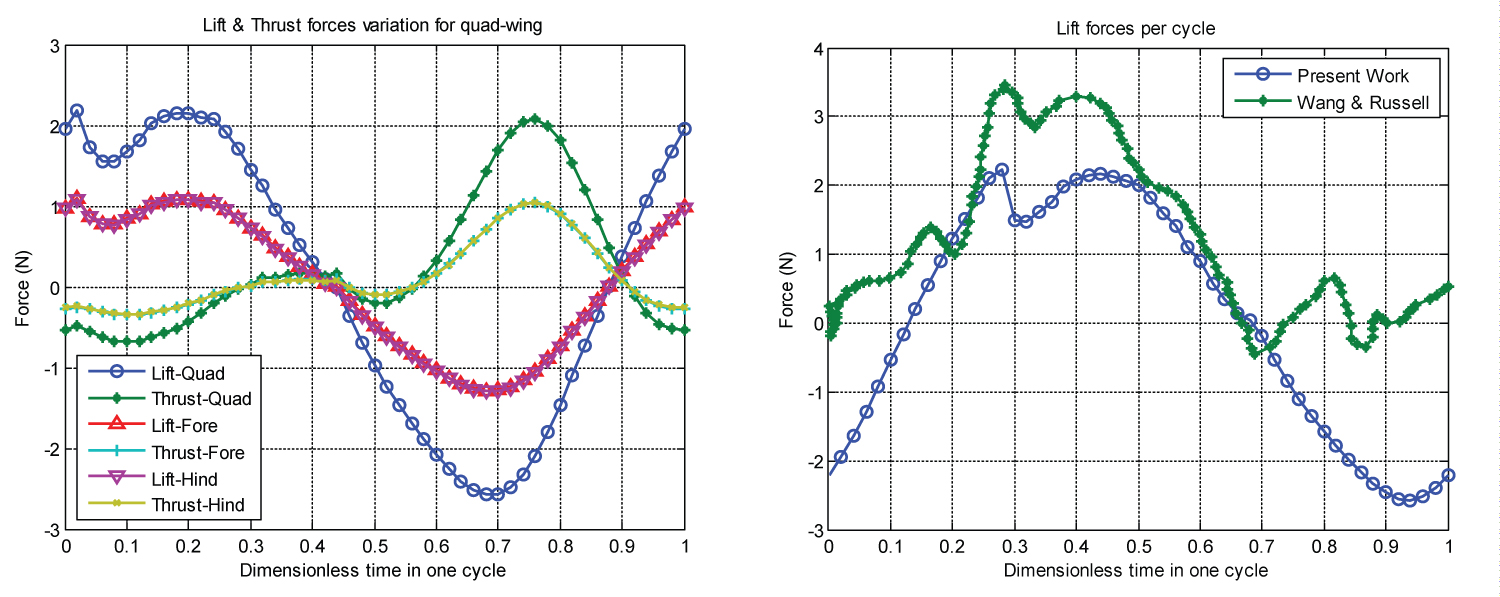
Figure 24: Left: Lift and thrust for quad-wing...
Left: Lift and thrust for quad-wing ornithopter; Right: Qualitative investigation with Wang & Russell results [3].

Figure 25: Variation of a) Lift...
Variation of a) Lift; b) Thrust with flapping motion phase shift between quad-wing's forewing and hindwing.
Tables
Table 1: Average lift and thrust of present work (bi-wing, semi-elliptical).
Table 3: Average lift and thrust (bi-wing) for each individual contribution.
Table 4: Average Lift and thrust variation with phase lag angle (bi-wing).
Table 5: Average lift and thrust values for simulated LEV schemes.
Table 6: Comparison of the average Lift and Thrust of rigid and flexible ornithopter wing using heuristic model using θ and h as basis of flexible deformation.
Table 7: Comparison of the average Lift and Thrust of rigid and flexible ornithopter wing using heuristic model using α' (alphaprime) as basis of flexible deformation.
Table 8: Comparison of the average Lift and Thrust of rigid and flexible ornithopter wing using heuristic model contributed by pitching and flapping motion.
Table 9: Comparison of the average Lift and Thrust of rigid and flexible ornithopter wing using heuristic model due to phase-shift between pitching and flapping motion.
Table 10: Average lift and thrust for present work.
Table 11: Average lift for quad-wing ornithopter for each pitching and flapping kinematic articulation.
Table 12: Average thrust for quad-wing ornithopter for each pitching and flapping kinematic articulation.
References
- Weis Fogh T (1973) Quick estimates of flight fitness in hovering animals, including novel mechanisms for lift production. Exp Biol 59: 169-230.
- DeLaurier JD (1993) An aerodynamic model for flapping wing flight. The Aeronautical Journal of the Royal Aeronautical Society 97: 125-130.
- Wang ZJ, Russell D (2007) Effect of forewing and hindwing interactions on aerodynamic forces and power in hovering dragonfly flight. Physical Review Letters 99: 148101.
- Ellington CP (1984) The aerodynamics of hovering insect flight III kinematics. Phil Trans R Soc London B 305: 41-78.
- Ellington CP (1999) The novel aerodynamics of insect flight: Applications to micro-air vehicles. The Journal of Experimental Biology 202: 3439-3448.
- Ellington CP (1984) The aerodynamics of hovering insect flight, I, quasi-steady analysis. Phil Trans of Roy Soc London B 305: 1-15.
- Ho S, Nassef H, Pornsinsirirak N, Tai YC, Ho CM (2003) Unsteady aerodynamics and flow control for flapping wing flyers. Progress in Aerospace Sciences 39: 635-681.
- Shyy W, Berg M, Ljungqvist D (1999) Flapping and flexible wings for biological and micro air vehicles. Progress in Aerospace Sciences 35: 455-505.
- Shyy W, Aono H, Chimakurthi SK, Trizila P, Kang CK, et al. (2010) Recent progress in flapping wing aerodynamics and aeroelasticity. Progress in Aerospace Science 46: 284-327.
- Dickinson MH, Lehmann FO, Sane SP (1999) Wing rotation and the aerodynamic basis of insect flight. Science 284: 1954-1960.
- Żbikowski R (2002) On aerodynamic modelling of an insect-like flapping wing in hover for micro air vehicles. Phil Trans R Soc Lond A 360: 273-290.
- Ansari SA, Żbikowski R, Knowles K (2006) Aerodynamic modelling of insect-like flapping flight for micro air vehicles. Progress in Aerospace Sciences 42: 129-172.
- Maybury WJ, Lehmann FO (2004) The fluid dynamics of flight control by kinematic phase lag variation between two robotic insect wings. Journal of Experimental Biology 207: 4707-4726.
- Theodorsen T (1935) General theory of aerodynamic instability and the mechanism of flutter. NACA.
- Kuethe AM, Chow CY (1986) The finite wing, Foundations of aerodynamics. (4th edn), John Wiley, New York, 145-164.
- Fujiwara T, Hirakawa K, Okuma S, Udagawa T, Nakano S, et al. (2008) Development of a small flapping robot motion analysis during take off by numerical simulation and experiment. Mech Sys Signal Processing 22: 1304-1315.
- Chen MW, Zhang YL, Sun M (2013) Wing and body motion and aerodynamic and leg forces during take-off in droneflies. J R Soc Interface 10: 20130808.
- Read DA, Hover FS, Triantafyllou MS (2003) Forces on oscillating foils for propulsion and maneuvering. Journal of Fluids and Structures 17: 163-183.
- Zakaria MY, Taha HE, Hajj MR (2014) Shape and kinematic design optimization of pterosaur replica. AIAA-2869.
- Yu C, Kim D, Zhao Y (2014) Lift and thrust characteristics of flapping wing aerial vehicle with pitching and flapping motion. Journal of Applied Mathematics and Physics 2: 1031-1038.
- Garrick IE (1936) Propulsion of a flapping and oscillating aerofoil. NACA Report No 567.
- Djojodihardjo H, Ramli ASS (2013) Kinematic and unsteady aerodynamic modelling, numerical simulation and parametric study of flapping wing ornithopter. Proceedings International Forum on Aeroelasticity and Structural Dynamics Bristol.
- Djojodihardjo H, Ramli ASS (2012) Generic and parametric study of the aerodynamic characteristics of flapping wing micro-air-vehicle. Applied Mech and Materials 225: 18-25.
- Djojodihardjo H, Ramli ASS, Surjatin Wiriadidjaja (2012) Kinematic and aerodynamic modeling of flapping wing ornithopter. Procedia Engineering 50: 848-863.
- Djojodihardjo H, Bari MAA, Mohd Rafie AS, Wiriadidjaja S (2014) Further development of the kinematic and aerodynamic modeling and analysis of flapping wing ornithopter from basic principles. Applied Mech and Materials 629: 9-17.
- Djojodihardjo H, Bari MAA (2014) Kinematic and unsteady aerodynamic modelling of flapping quad-wing ornithopter. 29th congress of the international council of the aeronautical sciences. St Petersburg, Russia.
- Scherer JO (1968) Experimental and theoretical investigation of large amplitude oscillating foil propulsion systems. Hydronautics Technical Report 662-1 Final.
- Multhopp H (1955) Methods for calculating the lift distribution of wings (Subsonic Lifting-Surface Theory). ARC R&M, No.2884.
- Pistolesi E (1933) Considerazioni sul problema delbiplano. Aerotecnica, 13: 185.
- Jones RT (1940) The unsteady lift of a wing of finite aspect ratio. NACA Report No 681.
- Garrick IE (1938) On some reciprocal relations in the theory of nonstationary flows. NACA Report No 629.
- Anderson JD (2004) Fundamentals of aerodynamics. (4th edn), McGraw-Hill, New York.
- Hoerner SF (1965) Fluid-dynamic drag.
- Jones KD, Platzer MF (2001) On the use of vortex flows for the propulsion of micro-air and sea vehicles.
- Von Karman T, Burgers JM (1943) General aerodynamic theory - perfect fluids. Aerodynamic Theory Division E 2: 1-24.
- Triantafyllou MS, Triantafyllou GS, Gopalkrishnan R (1991) Wake mechanics for thrust generation in oscillating foils. Physics of Fluids 3: 2835.
- Taylor GK, Nudds RL, Thomas ARL (2003) Flying and swimming animals cruise at a strouhal number tuned for high power efficiency. Nature 425: 707-711.
- Pennycuick CJ (1990) Predicting wingbeat frequency and wavelength of birds. The Journal of Experimental Biology 150: 171-185.
- Aditya K, Malolan V (2007) Investigation of strouhal number effect on flapping wing micro air vehicle. 45th AIAA Aerospace Sciences Meeting and Exhibit, Reno, Nevada.
- La Mantia M, Dabnichki P (2006) Unsteady panel method for oscillating foils.
- L Schouveiler, FS Hover, MS Triantafyllou (2005) Performance of flapping foil propulsion. Journal of Fluids and Structures 20: 949-959.
- Corum J (2003) The strouhal number in cruising flight.
- Ellington CP, Van den Berg C, Willmott AP, Thomas ALR (1996) Leading-edge vortices in insect flight. Nature 384: 626-630.
- Van den Berg C, Ellington CP (1997) The vortex wake of a "hovering" model hawkmoth. Phil Trans R Soc Lond B 352: 317-328.
- Usherwood JR, Ellington CP (2002) The aerodynamics of revolving wings i. model hawkmoth wings. J Exp Biol 205: 1547-1564.
- Bomphrey RJ, Lawson NJ, Taylor GK, Thomas ALR (2006) Application of digital particle image velocimetry to insect aerodynamics: measurement of the leading-edge vortex and near wake of a hawkmoth. Experiments in Fluids 40: 546-554.
- Shyy W, Liu H (2007) Flapping wings and aerodynamic lift -the role of leading-edge vortices. AIAA Journal 45.
- Yu Y, Tong B, Ma H (2003) An analytic approach to theoretical modeling of highly unsteady viscous flow excited by wing flapping in small insects. Acta Mechanica Sinica 19: 508-516.
- Birch JM, Dickson WB, Dickinson MH (2004) Force production and flow structure of the leading edge vortex on flapping wings at high and low Reynolds numbers. J Exp Biol 207: 1063-1072.
- Hu Z, Deng XY (2014) Aerodynamic interaction between forewing and hindwing. Acta Mechanica Sinica 30: 787-799.
- Alexander DE (1984) Unusual phase relationships between the forewings and hindwings in flying dragonflies. J Exp Biology 109: 379-383.
- Djojodihardjo H, Yee HH (2007) Parametric study of the flutter characteristics of transport aircraft wings. AEROTECH II, Conference on Aerospace Technology of XXI Century, Kuala Lumpur.
- Done GTS (1996) The flutter and stability of undamped systems. School of Engineering Science, University of Edinburgh, Report and Memoranda.
- Done GTS (1967) A study of binary flutter roots using a method of system synthesis. Aeronautical Research Council, R&M No. 3554.
- Kock J (2006) Physical and mechanical properties of chicken feather materials. MSc Thesis, Georgia Institute of Technology, USA.
Author Details
Harijono Djojodihardjo* and Alif S. S. Ramli
The Institute for the Advancement of Aerospace Science and Technology, Jakarta, Indonesia
Corresponding author
Harijono Djojodihardjo, The Institute for the Advancement of Aerospace Science and Technology, Jakarta, Indonesia.
Accepted: Augsut 11, 2018 | Published Online: Augsut 13, 2018
Citation: Djojodihardjo H, Alif SSR (2018) An Assessment of a Linear Aerodynamic Modeling of a Generic Flapping Wing Ornithopter. Int J Astronaut Aeronautical Eng 3:017.
Copyright: © 2018 Djojodihardjo H. This is an open-access article distributed under the terms of the Creative Commons Attribution License, which permits unrestricted use, distribution, and reproduction in any medium, provided the original author and source are credited.
Abstract
A comprehensive linearized aerodynamic approach is elaborated to summarize the author and coworkers effort to model flapping bi- and quad-wing ornithopter in producing lift and thrust for forward flight. The objective of the modeling is to assess the extent of linearized aerodynamic approach in mimicking mid-sized flapping Biosystems like bats and birds. Viscous effect and leading-edge suction is utilized in the basic Unsteady Aerodynamic Approach. Analysis is carried out by differentiating the pitching and flapping motion phase-lag and studying its respective contributions to the flight forces. Observation based heuristic modeling of Leading Edge Vortex is developed to study its influence on Lift and Thrust. The influence of the Strouhal number on the propulsion generation is also simulated and studied. Encouraging results are discussed in comparison with existing models in the literature, with a view to gain insight in developing a practical ornithopter model. The objectives and contributions of this work are to present and asses the merit of a simple approach based on first principles in revealing particular characteristics, and to investigate some critical and relevant characteristics that could be tackled with a simple approach.
Keywords
Bi-wing ornithopter, Flapping wing aerodynamics, Flapping wing ornithopter, Micro air vehicle, Quad-wing ornithopter
Nomenclature
A: Area also Amplitude (depending on context); AR: Aspect Ratio; B: Semi-wingspan; b: Semi-Chord; c: chord; C(k): Theodorsen Function; C(k)jones : Jones Modified Theodorsen Function; Cdf : Drag Coefficient due to Skin Friction; Cn: Normal Force Coefficient (as defined in eq.(4)); d: Distance Between First Quarter of Fore-Wing and Third Quarter of Hind-Wing; dDcamber: Sectional Force due to Camber; dDf: Sectional Friction Drag; dFx: Sectional Chordwise Force; dL: Sectional Lift; dy: Width of Sectional Strip Under Consideration; dN: Sectional Total Normal Force; dNc : Sectional Circulatory Normal Force; dNnc: Sectional Apparent Mass Effect; dT: Sectional Thrust; dTs: Leading Edge Suction Force; F(k): Theodorsen Function Real Component; G(k): Theodorsen function imaginary component; : plunging (heaving) rate; k: Reduced Frequency, as defined by , L: Total Lift; Lfore: Lift Force of Fore-Wing; LE: Leading Edge; LEV: Leading Edge Vortex; m: Mass, Wing or Body (as elaborated in the corresponding text); Q: vertical velocity at ¾-chord point; s: Dimensionless Distance as Defined by ; t: Time; S: Strouhal Number; T: Total Thrust; TE: Trailing Edge; TEV: Trailing Edge Vortex; U: Flight Velocity; V: Relative Velocity at Quarter Chord Point; Vx: Flow Speed Tangential to Section; Vrel: Relative Velocity at ¾-Chord Point; Vi: Induced Velocity; w: Vertical Velocity: Usinα; w0: Downwash Velocity at ¾-Chord Point; y: Spanwise Coordinate in the Body Coordinate Frame of Reference.
Greek Symbols
α: Angle of Attack; Angle Between Wind Velocity and Wing Chordline (or longitudinal body axis; as applicable by context); α': Flow's Relative Angle of Attack at Three-Quarter Chord Point; α0: Zero-Lift Angle; αrel: Relative Angle of Attack; Angle Between Relative Velocity Vrel and Wing Chordline (or longitudinal body axis; as applicable by context); α: Relative Angle of Attack; αTheodorsen: Phase Angle of Theodorsen Function, Defined by eq. (17); β: Flapping Angle; β0: Amplitude (Maximum) of Flapping Angle; Γ: Circulation; γf: Flexibility Factor; γf: 1 Refers to a Rigid Wing; θ: Pitching Angle; θ0: Amplitude (Maximum) of Pitching Angle; θhindwing: Effective Pitching Angle of Hind-Wing; θf: Angle of Flapping Axis with Respect to Flight Velocity (incidence angle); θfp: Mean Pitch Angle of Chord with Respect to Flapping Axis; θp: Pitch Angle of Chord with Respect to Flapping Axis; θfp = θf + θp : The Sum of the Flapping Axis Angle with Respect to Flight Velocity and the Mean Angle of the Chord Line with Respect to the Flapping Axis; φ: Phase Angle Between Pitching and Flapping Angle; ηs: Efficiency Coefficient; ω: Flapping Frequency; ρ: Air Density
Subscripts and Symbols
Mid-Chord: Referring to Values at Mid-Chord; : Time Derivative of .
Introduction
The present work comprehensively summarizes a series of work that have been carried out by the author and co-workers in utilizing a generic approach to model the kinematics and aerodynamics of flapping wing ornithopter using first principles and linearized aerodynamics, and by focusing on a flapping bi-wing and quad-wing ornithopter in producing lift and thrust in forward flight. With its simplicity of approach, certainly it cannot replace the hosts of more sophisticated computational and experimental approaches that have meticulously taken many critical aspects of the flapping wing phenomena. Rather, the emphasis, referring to Weis-Fogh [1], has been placed on simplicity in the approach for quick estimate. The objectives and contributions of this work are (i) To present and asses a simple approach which are based on first principles, translated into in house computational programs that should be capable of revealing particular characteristics, for conceptual design tool and establishing a simple and workable model. (ii) To review and establish a baseline of the state of the art based on the wealth of literature to date as a check points. (iii) To summarize some critical and relevant characteristics, and identify which of these could be tackled with a simple approach, and which cannot. (iv) To assess the usefulness and limitations of the approach, which will be useful for further elaborate approach.
The work does not involve the development of viscous flow based CFD or fluid dynamic approach nor utilize commercially developed one, with more meticulous considerations of in-depth critical factors (with higher sophistication and fidelity). In short, the work was inspired by DeLaurier straight forward approach [2], and was based on the use of basic fluid dynamic principles like aerodynamic strip theory, Theodorsen unsteady aerodynamics, and derived empirical formula for three dimensionality and viscous effects. A posteriori assessment will elaborate the limitation of the work, and ways (using similar philosophy) for further development. To some extent, the work represents a propaedeutic, heuristic and surrogate approach.
Through a priori meticulous assumptions and sound application of first principles, the approach should be capable to reveal pertinent features of the physical phenomena to a favorable extent. A posteriori assessment of such approach would judge the extent of its applicability. Since the true flight system is so complicated, the approach involves approximations which may not be tractable using first principles in their simple forms.
However, when the analysis is confined to free flight and make use of the most reliable flight data available, the task will be more manageable, since it is possible to introduce simple corrections [1].
Another main objective is representation of flapping ornithopter principle for forward flight. To tackle hovering case, additional approach is summarized in an Appendix. Other more involved phenomena, such as LEV and TEV, will be approached by physically reasonable heuristic modeling. Since the focus of the present work is on medium-sized bird like ornithopter and is intended to cover and imitate the flapping-wing forward flight of birds, and not insects, clap and fling phenomena, which is more pronounced in insects and hummingbird, is not addressed at this stage. Quad-wing is dealt with as an extension of the approach developed. Though machines may differ in form, the present approach is intended for the design of MAV in the order of scale as flying medium-sized birds, as schematically depicted in Figure 1. For the study, a baseline 15 cm semispan bi-wing configuration has been adopted, somewhat in the order of a dove. However, for other specific cases, other dimensions have been adopted, as elaborated in the manuscript in appropriate places.
A generic approach is followed to understand and mimic the unsteady aerodynamics of biosystem that can be adopted in a simple and workable Bi- (BWMAV) and Quad-Wing Micro Air Vehicle (QWMAV) model. Figure 2 and Figure 3 exhibit biosystems, in particular an eagle and a dragonfly, which will be mimicked in modeling the geometry of simple flapping baseline bi- and quad-wing ornithopter configuration, respectively. The geometries of both systems studied are depicted in Figure 2, bottom-right, for the biwing flapping ornithopter and Figure 3b for the quadwing ornithopter, with the size of a midsized bird.
To assess the applicability of the linear aerodynamic modeling elaborated in the present work, the governing basic equations will be elaborated in the subsequent sections. In addition, parametric study will be utilized to gain further insight to this end.
The computational procedure utilized in the present series of approach to some extent follow the linearized approach of DeLaurier [2], who has made the first successful attempts to develop birdlike flapping flight. Comprehensive account on flapping wing biosystems that has been given among others by Weis-Fogh [1], Ellington [4-6], Ho, et al. [7], Shyy, et al. [8,9], Dickinson, et al. [10], Żbikowski [11] and Ansari, et al. [12] will be taken into account in developing the linearized computational model. Although the present interest in developing a mathematical and experimental model is on more or less rigid bi- and quad-wing ornithopter, relevant aspects of insect and hummingbirds may also be taken into considerations as appropriate.
The development of flapping wing modeling and simulation is first applied to flapping bi-wing designs for forward flight. Using similar scheme, the forward flight of quad-wing will be simulated also. At this point, it is of interest to note that the dragonfly has the capability to shift flight modes from forward, backward, sideways and hover by simply varying the phase lag between its fore and hind wings Maybury and Lehmann [13]. Wing flexibility is also elaborated utilizing the present linearized approach in later sections.
Theoretical Modeling of the Generic Aerodynamics of Flapping Wings
The theoretical modeling of the Generic Aerodynamics of Flapping Wings follows the Quasi-steady and unsteady model analytical approaches which have been carefully developed and applied in order to deal with the aerodynamic problem. Following DeLaurier [2], the flapping flight can basically be classified into two categories; (1) The quasi-steady model where unsteady wake effects are ignored, and (2) The unsteady aerodynamic model by modelling the wake. Accordingly, the present aerodynamic approach is synthesized using the generic contributions of the motion elements of the biosystems' bi-wing and quad-wing basic characteristics, which comprise the strip theory and thin wing aerodynamic approach (DeLaurier [2], Theodorsen [14], Kuethe and Chow [15]. Leading edge suction is included following the analysis of Polhamus [16,17] and DeLaurier's approximation [2]. Three dimensional effects are introduced by using Scherer's modified Theodorsen-Jones Lift Deficiency Factor [18], in addition to the Theodorsen unsteady aerodynamics [19] and its three dimensional version by Jones [20]. Garrick's leading edge suction [21] is also incorporated.
Certain physical parameters that can be identified via observations and established results of various researchers are also considered, as appropriate, in the computational model. Flapping wing unsteady aerodynamics using a modified strip theory approach is synthesized with and without post-stall behavior. Figure 4 summarizes the Flow-Chart of the computational logic.
The results obtained by Djojodihardjo and Ramli [22-24] and Djojodihardjo and Bari [25,26] in analyzing the wing flapping motion by looking into the individual contribution of the pitching, flapping and coupled pitching-flapping to the generation of the aerodynamic forces will be further elaborated through further scrutiny of the motion elements. Three distinct flapping motion of the wing can be distinguished; these are: a) Flapping, which is up and down plunging motion of the wing; b) Feathering is the pitching motion of wing and can vary along the span; c) Lead-lag (or fore-and-aft oscillation), which is in-plane lateral movement of wing, as exhibited in Figure 5. In addition, further analysis in the present work is carried out to study the phase lag between pitching and flapping motion, which should be differentiated with the fore-and-aft movement of the wing along its mean plane.
The degree of freedom of the motion is also depicted in Figure 5. The flapping angle β and pitching angle θ vary as a cosine function, as given by the following equations.
Here θ0 and βo represent the amplitude for pitching and flapping angle respectively, Φ represents the lag angle between pitching and flapping and y is spanwise distance along the wing. The sum of the flapping axis angle with respect to flight velocity (incidence angle) and the mean angle of the chord line with respect to the flapping axis is denoted by θfp. As a baseline, semi-elliptical planform wing has been utilized. By referring to Eq. (1) and Eq. (2), β and θ is considered to oscillate following a cosine function by default and also, the scheme indicates that these motions start from their maximum values. A different scheme, however, can be adopted, by introducing phase lag to this oscillatory motion. Leading edge suction is included following the analysis of Garrick [21] and DeLaurier's approximation [2]. Three dimensional effects are introduced by using Scherer's modified Theodorsen-Jones Lift Deficiency Factor [27]. The bound circulation, following Multhopp approach (Multhopp [28]), is located at the quarter-chord line and the downwash is calculated at the three-quarter-chord line for each strip (as first elaborated by Pistolesi [29]).
For the sake of completeness, the angle θfp is defined here to allow the possibilities that the mean pitch angle of chord with respect to flapping axis is not zero, while the angle of flapping axis with respect to the flight velocity (incidence angle) is defined as θf. Without loss of generalities, no linear variation of the wing's dynamic twist is assumed, so that θfp, mean pitch angle of chord with respect to flapping axis , can be simply assumed to be equal to θf, angle of flapping axis with respect to flight velocity (incidence angle) throughout the present work, since θfp = θf + θp, where
θf = Angle of flapping axis with respect to flight velocity (incidence angle)
θfp = Mean pitch angle of chord with respect to flapping axis
θp = Pitch angle of chord with respect to flapping axis
Furthermore, if the flapping is assumed to be coincident with the direction of motion, both values reduce to zero. In principle, using the principle of superposition in linearized aerodynamics, additional requirements can readily be added.
The vertical and horizontal components of the resultant force produced by the wing are the lift, thrust and drag.
Then the total normal force acting perpendicularly to the chord line and given by
The circulatory normal force for each section acts at the quarter chord and also perpendicular to the chord line is given by
Where
Using these relationships, the relative velocity at three-quarter chord point which is used for the calculation of the aerodynamic forces can be established. The three quarter chord theorem was first derived by Pistolesi [29] for the properties of the bound vortices on a wing of infinite aspect ratio. It states that, concentrating the lift at the quarter-chord line, the downwash produced by it at the three-quarter chord line is the same as that produced by the flat-plate vortex distribution, equation (7), which is constant along the chord.
The relative angle of attack at three-quarter chord, α, is then given by
and α is a periodic function of time
Where A is its amplitude and which is schematically elaborated in Figure 6.
The modified Theodorsen Lift Deficiency function for finite aspect ratio wing is given by Jones [30]. Another derivation for unsteady forces for finite aspect ratio wing carried out by Scherer [28]. He arrived at a similar form to the Theodorsen two-dimensional case, and his expression is utilized here for convenience; it takes the following form
Where
C(k), F(k) and G(k) relate to the well-known Theodorsen function [14,30] which are functions of reduced frequency, k. Following the methodological philosophy of Theodorsen [14] and Garrick [31] classical unsteady aerodynamics, the unsteady lift (2D or per unit span) is expressed as
Where Q is given by . Then, substitution Q into eq. (11) gives
The convenience of the Complex Analysis of Theodorsen is exemplified by Garrick [31] by associating the imaginary part of (11) and (12) with the lift [31]. The details are elaborated for the sake of completeness. The reduced frequency is defined as , or where . Assuming sinusoidal motion
or
Combining (10) and (13), one obtains:
Note that
Where the imaginary value of Eq. (15) is the lift:
After some algebraic manipulation, Eq. (15) reduces to
and the Imaginary Parts (I.P) of the above equation is
Therefore, for each chordwise strip along the wing span:
Consistent with the strip theory, the downwash for untwisted plan form wing is given by (Kuethe and Chow [15], Anderson [32])
Considering all of these basic fundamentals, the relative angle of attack at three-quarter chord point α' is given by
Which has taken into account the three dimensionality of the wing.
If stall is taken into account, then following a certain criterion for attached flow over the section as also adopted by DeLaurier [2]; the stall angle should be defined a priori. In the examples worked out in the present work, without loss of generalities, it is assumed that
αstall_max ≡ 20° = 20*π/180 radian (25)
Criterion for attached flow over the section (from DeLaurier [2])
The coefficient of the wing will be assumed to be similar to the drag of a flat plate; referring to Hoerner [33], this value is assumed to be
CD-post-stall ≡ 1.98 (27)
From Figure 5, the flow velocity which include the downwash and the wing motion relative to free-stream velocity, V can be formulated as
The third and fourth terms are acting at the three-quarter chord point. The apparent mass effect for the section is perpendicular to the wing, and acts at mid chord, and can be calculated as
The term is the normal velocity's time rate of change at mid-chord due to the motion of the wing.
The total chordwise force, dFx is accumulated by three force components; these are the leading edge suction, force due to camber, and chordwise friction drag due to viscosity effect. All of these forces are acting along and parallel to the chord line.
Following Garrick [34], the leading edge suction, dTs is given by
and the chordwise force due to camber and friction is respectively given by [2]:
To account for viscosity effects, the efficiency term ηs is introduced for the leading edge suction dTs.
The resulting vertical and horizontal components of the forces at each strip dy, which are perpendicular and parallel to the free-stream velocity, respectively is then given by
To obtain a three dimensional lift and thrust for each wing, these expressions should be integrated along the span; hence
For this particular case, numerical computations are performed using the following wing geometry and parameters: the wing of 40 cm, aspect ratio of 6.36, flapping frequency of 7 Hz, total flapping angle of 60°, forward speed of 6 m/s, maximum pitching angle of 20°, incidence angle of 6° and there is no wing dihedral angle. In the calculation, both the pitching and flapping motions are in cosine function by default, which is subject to parametric study, and the upstroke and downstroke have equal time duration.
Validation of Bi-Wing Theoretical Modeling Results
The computational scheme outlined in previous sections can be validated by comparing the results with the work of DeLaurier [2] and Zakaria, et al. [19], using the pterosaur's wing model. The comparison is exhibited in Figure 7. The result of using the present bi-wing computational routine for the pterosaur wing geometry and parameters of [2] and [19] is shown in Figure 7 ((a) for Average Lift and (b) for Average Thrust) and their average values shown in Table 1. Figure 7b also shows the effect of the inclusion of post stall behavior to account for the actual angle of attack within a cycle following the procedure elaborated in Section II. At a certain value, the angle of attack exceeds maximum stall angle to enter into the region of post-stall condition, even though the angle is only accounted for the upper (positive) limit, following DeLaurier's assumption in his work.
In Figure 8 and Table 2, geometric and kinematic parameters used by Yu, et al. [20] are taken into account to produce comparable qualitative and quantitative agreements with their results; the latter were calculated using three-dimensional unsteady vortex lattice method Figure 9.
Separation of Bi-Wing Forces into their Components
Another study is carried out to investigate the influence of individual contributions of the pitching-flapping on the flight performance. Results obtained as exhibited in Figure 10 and Table 3, show that the lift is dominated by the incidence angle while the thrust is dominated by the flapping angle (other parameters remaining constant).
From the above component-wise force analysis, it can be deduced that also an appropriate combination of these force elements can be obtained to produce optimum lift and thrust. The optimization of this problem is also currently under study.
The Influence of the Phase-Lag between Pitching and Flapping Motion and the Individual Motion Component on the Flight Performance
To investigate the influence of the phase lag between pitching and flapping motion to the generation of lift and thrust, a parametric study is carried out. As exhibited in Figure 11, the optimum lift and thrust can also be obtained by appropriate choice of this phase lag. From this study, it is observed that the lift reaches its maximum value when the phase lag angle between pitching and flapping motion is Φ = π/2, whereas the thrust is maximum when Φ = 3π/4. Hence an ornithopter can be tailored or controlled to achieve one of these values. Otherwise, an optimization process should be developed in this regard.
Variation of Oscillatory Articulation of the Bi-Wing
Based on a close observation to selected avians, such as soaring eagles, one can observe that before taking off, they expand (flap) their wings up to a maximum position and stretch their legs simultaneously, as exhibited in Figure 12. It follows, that the oscillatory motion can be modeled as a cosine function, since a cosine function at t = 0 has its maximum value. It is noted, however, that many researchers did their studies with different kinematic settings for flapping and pitching motions. Motivated by these meticulous observations, various possible models can be defined and utilized accordingly to account for every possible flapping kinematics. The results are shown in Figure 13 and Table 4.
What can be seen is that, in conformity with our observation and those researchers like DeLaurier [2], Fujiwara, et al. [16] and Chen, et al. [17], flapping motion should be in cosine function. Interestingly, as observed by Chen, et al. and assumed by DeLaurier, the pitching motion is prominent in negative sine function and exhibited by our calculation. Table 4 lists the average lift and thrust for various pitching flapping phase lag. Judging from these results, at least within the assumptions adopted in the present work, one can obtain an impression that combination of cosine flapping pitching with a phase lag between π/2 and 3π/2 may produce the optimum value of lift and thrust forces, as also exhibited in Figure 10.
These results exemplify that the flapping kinematics can produce significant aerodynamics forces and the sensitivity of the lift and thrust produced to the oscillatory articulation could be utilized for tailoring or optimization purposes.
Propulsive Force and Strouhal Number Relationship in Bi-Wing
Von Karman and Burgers [35] offered the first theoretical explanation of drag or thrust production based on the resulting vortex street. For flapping airfoil, Jones and Platzer [34] demonstrates that the vortex streets characteristic of drag production exhibit a row of clockwise vortices above the symmetry plane, and a row of counter-clockwise vortices below the symmetry plane, as shown in Figure 14a. The vortices induce a velocity or momentum deficit on the centerline indicative of drag, for an airfoil plunging at a low Strouhal number (k = 3.6, h = 0.08, St = 0.29). Due to the production of drag, the wake wavelength, λ, which is defined as the distance between vortex centers of same rotation, is shorter than the wavelength predicted by linear theory, λl.t. = 2π/k. Oscillating the airfoil more energetically the vortex street shown in Figure 14b is generated (k = 3.0, h = 0.20, St = 0.60), which produces thrust.
The biological and physical properties of the wings and muscles, as well as the wing dynamics of an insect or bird dictate the range of operation of their relevant parameters. These parameters, such as the flapping frequency should be optimal for ideal flight performance. Triantafyllou, et al. [36] showed that 'optimal' flapping occurs when the Strouhal number is in the range of 0.2-0.3. As stipulated by Taylor, et al. [37], the Strouhal numbers for birds, bats, and insects flying at cruising speed are within similar range of values. An optimal Strouhal number alone, however, does not determine an optimal frequency. Referring to equation of Strouhal number below, the flight speed and flapping amplitude play important role in determining the Strouhal number. Therefore proper considerations of these parameters is required to evaluate the flapping wing characteristics based on Strouhal number.
The Strouhal number can be defined as
Pennycuick [38] experimentally derived the correlation of the wing-beat frequency for flapping flight to the body mass, wingspan, wing area and the wing moment of inertia. For birds with the body mass ranging from 20 g to nearly 5 kg the wing beat frequency is correlated by the following formula [38]:
In addition, the relation between flight speed (m/s) and the mass (gram) of a bird can be given by
Where m (in equation (39) is the bird's body mass in kilogram, g is the gravitational acceleration, b is the wingspan, S is the wing area and ρ is the air density. Using such correlations from Pennycuick [38], the wing beat frequency calculated is 2.96 Hz, which corresponds to Strouhal number of about 0.17, in agreement with Aditya and Malolan's [39] experimental results.
Figure 15 is produced from the bi-wing results [22-26] using the present rectangular bi-wing computational modeling as a baseline, for pitching oscillation. Comparison made with the panel method results of La Mantia and Dabnichki [40] and MIT experimental results of Read, et al. [18] and Schouvelier, et al. [41] show reasonable qualitative agreement.
Noting that the present bi-wing three-dimensionally modified strip-theory unsteady aerodynamic approach utilizes simple and direct approach, such agreement is encouraging for further development.
It is of interest to compare the Strouhal numbers where there are reasonably good agreements between those stipulated by [18,40,41] and our computation with the distribution of Strouhal Numbers for 22 different bird species as elaborated by Corum [42] in his study relating the flapping amplitude, wavelength (distance travelled per flapping cycle and Strouhal number, as depicted in Figure 16, with supporting observation of Taylor, et al. [37]. Aditya and Malolan [39] found that the magnitude of peak thrust increase with the increase in flapping angle and maximum propulsive force is produced around a Strouhal number of 0.15 Aditya and Malolan conjectured that with a simple rule of thumb, the flapping wing Micro-Air Vehicle (MAV) of 15 cm span cruising with a 80° stroke angle at 5-6 m/s should attain maximum efficiency at a wing-beat frequency of about 8-10 Hz.
Modeling and Parametric Study of the Influence of Leading Edge Vortex (LEV) on Bi-wing Flapping Motion Aerodynamics
Many literature, such as Ellington, et al. [43], Van den Berg and Ellington [44] and Usherwood and Ellington [45] reported or discussed the notion that in insects and certain birds lift was enhanced by the presence of a Leading Edge Vortex (LEV). The lift coefficient can be as high as 2 that can be maintained within approximately 3 chord lengths of travel after the initial start, when the LEV was formed, then drops due to the shedding of the LEV. However, it is observed that the LEV on the flapping wings of the hawkmoth Manduca Sexta did not shed in the translational phases of the down- and the up-strokes, and the stall effect could be avoided during the entire stroke. It was suggested that the spanwise flow prevented the LEV from detaching.
Digital Particle Image Velocimetry (DPIV) measurements of Bomphrey, et al. [46], as exemplified in Figure 17h show the presence of a significant leading-edge vortex during the downstroke. Shyy and Liu [47] noted that there is a controversy concerning the role of the Leading-Edge Vortex (LEV) in enhancing aerodynamic lift during flapping flight. They stipulated that the LEV is generated from the balance between the pressure gradient, the centrifugal force, and the Coriolis force in the momentum equation. The LEV generates a lower pressure area, which results in a large suction on the upper surface.
Based on such information, which may not be exhaustive, and noting that the focus in the present study is on rigid flapping wing ornithopter mimicking medium-sized birds, a heuristic modelling is introduced to study the influence of a Leading Edge Vortex (LEV) on the flapping flight performance, using two heuristic approaches. The merits of such heuristic approaches are two folds; first, to study how the influence of LEV on the oscillatory motion of bi-wing flapping system can be simulated, and second to take advantage of such scheme, if viable, for the design and control of a flapping MAV. Such procedure to a certain extent could mimic the influence of LEV in a biosystem; in addition, such setting can be easily simulated in a mechanized ornithopter. Following such heuristic approach, a parametric study is carried out to simulate and assess the discontinuous motion that may produce lift and thrust enhancement.
The first heuristic model assumes a discontinuous LEV interaction, by considering the discontinuity to be contributed by instant vortex shedding at the leading edge for a relatively short duration (for instance, first half of downstroke phase). To serve as a baseline, the development of the simulation is based on the following rationale:
a) LEV is assumed to occur as part of the pitching motion.
b) LEV is created due to sudden downstroke movement of the leading edge; from biological and performance optimization reason, LEV is assumed not to be created during the upstroke.
c) LEV is created during the sudden change of motion which is assumed to take place within a fraction of each stroke. For illustration, without loss of generalities, that fraction is assumed to be in the order of 30%-90%.
d) These assumptions are applied only to the pitching motion. Leading edge suction is incorporated. In addition, skin friction and three-dimensional effects are not considered. To obtain the total lift and thrust per cycle, similar to the procedure followed in the absence of LEV, the effect of these three flapping motion components should be superposed to the resulting discontinuous pitching motion.
The results are exhibited in Figure 17. Figure 17a indicates that by performing discontinuous pitching oscillation following the first heuristic model, marginal lift improvement to the flapping aerodynamic performance by LEV is produced compared to the original continuous one (that is, without LEV). Similarly, no significant LEV contribution to thrust is indicated (Figure 17b). As exhibited by Figure 17e, the latter behavior may be attributed by the dominant role of the leading edge suction.
The second heuristic model incorporates a LEV that once it was formed, it will remain active over the wing to simulate an increase in the oscillating wing lift during the whole downstroke, and it is shed off during the upstroke. The upstroke is performed similar to the baseline situation. To account for such heuristic LEV scheme, the computation will be based on the apparent angle of attack α', which will be incorporated in the aerodynamic calculation for both lift and thrust.
Furthermore:
a) There is no stall nor post-stall effects, since the LEV is assumed to prevent stall during the downstroke;
b) When α' is positive, the lift force is increased by an estimated 30% to 90% of the baseline situation (without LEV) .
c) During the upstroke, the wing oscillatory motion behaves like the baseline situation.
The results are shown in Figure 17c and Figure 17d. In c, a sinusoidal baseline motion is assumed, and in the latter, a cosine function based oscillation. Three situations are illustrated, for an LEV producing 30%, 60% and 90% increase of the downstroke lift, respectively. It can be seen, that such scenario produces significant increase on the lift force. Figure 17e is provided, to obtain some insight on the dominating influence of thrust. Figure 17b shows that the introduction of simulated leading edge vortex on the partial motion during downstroke does not give significant influence on thrust. In this case, the leading edge suction may play a dominant role. For qualitative comparison, Figure 17f is prepared to include the results of Yu, et al. [48] and Dickinson, et al. [10]. In both present heuristic approaches, realizing that during the supination, the LEV is shed from leading edge, a separation bubble is then formed. Therefore, in the calculation, the baseline forces on the wing will be based on a separated flow (that is the stall case). It should be noted, that the results were obtained for insects, while our models are for medium sized birds or ornithopter. For medium sized birds in forward flight, no such observation is available. Nevertheless, the above study will be useful for providing an insight for the more involved design of rigid flapping wing ornithopter mechanism. Associated with Figure 17, Table 5 exhibits the average lift and thrust values for the simulated LEV schemes. As supplementary considerations, Figure 18 is presented to exhibit the baseline difference in α'. Figure 18a exhibits the baseline difference in α' associated with sinusoidal, while Figure 18b cosinusoidal pitching motion.
Incorporation of Aerodynamics Flexibility in a Quasi-Steady Heuristic Model for Aerodynamic Performance Estimation
Based on the findings obtained in previous section, a heuristic aeroelastic model can be established. The simplest one is to incorporate the influence of the aeroelastic properties being reduced to the static flexibility properties. It is also assumed that the flexibility effect acted instantly. Following such rationale, then the effect of aeroelasticity, hence flexibility, is to modify the pitching and heaving angle linearly to a small percentage. The results of such heuristic model assumption to the aerodynamic performance of the flapping wing ornithopter can be calculated using the procedure already outlined in section one. Essentially, a constant Flexibility Coefficient γf is introduced to account for flexibility of the wing in pitching and flapping motion. The basis of such rationale is the result of low frequency aeroelastic analysis elaborated in Appendix. Then the pitching and heaving motion will be modified as follows
The results are exhibited in Figure 4a and Figure 4b, which describe the influence of the flexibility on the lift and thrust produced by the flapping wing, if the flexibility effects is introduced on θ and h. All the results are computed by considering the dynamic stall criterion for attached flow similar to that utilized by DeLaurier [2].
Figure 19a and Figure 19b and Table 6 show the influence of introducing 5% and 10% flexibility as a representation of the aeroelastic effect using quasi-steady aerodynamics. If the flexibility factor γf is introduced into the apparent angle of attack α' , the prevailing equation will be modified as;
Here, γf = 1 refers to a rigid wing. The results are exhibited in Figure 20a, Figure 20b and Table 7. These results show that the effect of static aeroelasticity tends to reduce the lift, and increase the thrust. In addition, the introduction of the static aeroelasticity introduced to the primary variables θ and h will produce slightly different values than if the aeroelastic effect is introduced in the derived variable α'. Noting that the heuristic model is a first approximation to the actual state of affairs, such difference may be attributed to many simplifying assumptions, such as the three dimensionality of the flow as represented by α', among others.
Proceeding to the investigation on the static aeroelasticity effects on the individual contribution of pitching and flapping motion components, the results are shown in Figure 21a, Figure 21b and Table 8. For this particular study, the incidence angle is assumed to be zero. These figures show that the contribution of static aeroelasticity to flapping is more apparent than to pitching.
Next the static aeroelasticity effects on the phase lag between the Pitching and Flapping Motion Components is investigated, and the results are shown in Figure 22a, Figure 22b and Table 9. For this particular study, the incidence angle is also assumed to be zero. In this study, a parametric study is carried out by varying the phase lag between flapping and pitching from 0° to 360° (2π). The results as exhibited by these figures show the extent the contribution of static aeroelasticity to the influence of the phase lag between the pitching and flapping motion on the lift and thrust generated by the flapping wing ornithopter.
Modeling of Quad-wing
The quad-wing will be modeled based on the modelling and encouraging results obtained for bi-wing.For the quad-wing kinematics and aerodynamics, the present work takes into account the influence of the forewing induced downwash on the hindwing effective angle of attack.This effect is modeled by assuming that the hindwing is governed by similar equations applied to the forewing, and an additional induced downwash is calculated at the three quarter-chord point of the hindwing, as depicted in Figure 18. Following Kutta-Joukowski Law, the instantaneous equivalent circulation generated by the forewing is given by
and the induced velocity Vi , following Biot-Savart law is given by
Following a two-dimensional approximation without considering the three dimensionality of the entire wing system.
Following Figure 23, for small angle of attack, an additional induced downwash due to the forewing on the hindwing acting on the latter three-quarter chord is given by Vi. Accordingly, an additional angle of attack on the hindwing is given by
Therefore the pitching angle of the hind wing is given by
Then the calculation of the aerodynamic forces follows similar procedure like the forewing as isolated wing, i.e. the baseline for the bi-wing. This formula, however, ignores the effects of the trailing vortices of the forewing, the leading edge vortex and the post-stall behaviour, which are mentioned by others (i.e. Maybury and Lehmann [13], Birch, et al. [49]) that will modify and signify the baseline formulation for the hindwing, especially during lift recovery phase. This notion as well as the two-dimensional approximation for the induced downwash should be further elaborated and their effects should be incorporated in future work.
Results for Quad-Wing
Simulation results
Initial initiative was carried out with an assumption that the fore and hind wings are closely spaced, that is there is no gap between the leading edge of the hind wing and the trailing edge of the fore wing. The results in Table 6 are obtained using the following wing geometry and parameters for both forewing and hindwing: The wingspan of 40 cm, aspect ratio of 6.36, flapping frequency of 7Hz, total flapping angle of 60°, forward speed of 6 m/s, maximum pitching angle of 20°, incidence angle of 6° and no wing dihedral angle. This analysis also accounts for the induced angle of attack on the hind wing due to downwash of the fore wing. The results are presented in Figure 24 and Table 10. Figure 24 (left) also shows the lift computed using the present simplified and generic model with no phase lag angle between forewing and hindwing.
For Figure 24 (right), qualitatively, some parts exhibit the same behavior. However, it should be noted that the total development of the lift per flapping cycle of the fore and hind wing will also depend on the phase shift between fore and hind wing. Therefore, by appropriate choice of phase shift, the lift development per cycle can be tailored, for instance with sinus function for flapping and pitching motion, to resemble those found by Wang and Russell [3]. This issue merits further study. However, this notion indicates the benefits of the present aerodynamics modeling using linear strip theory. Better agreements need the utilization of viscous flow analysis.
Variation of oscillatory articulation of the quad-wing
Following the procedure and parametric study carried out for bi-wing ornithopter [22-26], the present study also addresses the flapping kinematics of quad-wing ornithopter, by taking into considerations what has been learned from bi-wing parametric study. The forewing and hindwing are arranged in tandem without gap, so that the leading edge of the hindwing touches the trailing edge of the forewing, and they are moving simultaneously. Learning from natural observation, quad-wing insects like dragonfly change their wing motion kinematics for different flight modes, and the most obvious changes is the phase difference between forewing and hindwings. In a worked-out example, one may simulate the flapping quad-wing motion whereby the hindwing leads the forewing. Following such scheme, cosinusoidal motion for the pitching motion of both forewing and hindwing may be assumed, while one parameter, such as the phase-shift between the hindwing and forewing, is varied.
The results, as exhibited in Figure 25, shows that, among the other variations simulated, phase lag of π between quad-wing's forewing and hindwing produces the best average lift per cycle while for the average thrust per cycle, a phase shift value of π. In conformity with the observation by Hu and Deng [50] and Alexander [51] in their studies, the present work also shows that when quad-wing insect like dragonfly performs aggressive maneuvers, they will employ in-phase flight to generate larger optimized aerodynamic forces. Therefore further analysis to optimize the combination of these parameters with more sophisticated considerations should still be pursued.
Table 11 and Table 12 show the kinematic articulation in pitching and flapping of the fore- and hind-wings, to produce lift and thrust forces, respectively. These results also indicate variation of such oscillatory articulation possibilities that could be further tailored to meet certain objectives.
Conclusion
Following the objectives of the present work to present and asses a simple approach which are based on first principles, translated into in house computational programs that should be capable of revealing particular characteristics, numerical simulations have been carried out, compared and validated with other data from relevant literatures with similar unsteady aerodynamic approach and general physical data. In this conjunction, a computational model has been developed utilizing strip theory and two-dimensional unsteady aerodynamic theory of Theodorsen with modifications to account for three-dimensional and viscous effects and leading edge suction. The study is carried out on semi-elliptical wing planforms and rectangular ones as appropriate. Within the physical assumptions limitations; encouraging qualitative agreements or better have been indicated, which meet the proof of concept objectives of the present work. For the bi-wing flapping ornithopter, judging from the production of aerodynamic forces, the present flapping-wing model performance is comparable to those studied by Yu, et al. [20]. The analysis and simulation by splitting the flapping and pitching motion shows that: (a) The lift is dominantly influenced by the incidence angle (b) The thrust is dominated by flapping motion (c) Phase angle variation could be utilized to obtain optimum lift and thrust for each wing configurations. For the quad-wing ornithopter, the simplified computational model adopted verified the gain in lift obtained as compared to bi-wing flapping ornithopter, in particular by the possibility of varying the phase shift between the flapping and pitching motion of individual wing as well as between the fore- and hind-wings.
Based on the wealth of literature to date that has been reviewed, a baseline of the state of the art employing linearized aerodynamic approach has been established. Some critical and relevant characteristics are identified and summarized, and as appropriate, these have been simulated using linearized aerodynamic approach and physically feasible heuristic model. The results are assessed to identify which of these could be tackled with a simple approach, and which cannot. By assessing the numerical results obtained, the usefulness and limitations of the approach can be gained, which will be useful for further elaborate approach and preliminary design of experimental model. A posteriori assessment elaborates the limitation of the work, and ways to pursue further development. The work has been focused on the representation of flapping ornithopter in forward flight.
A structured approach has been followed to assess the effect of different design parameters on lift and thrust of an ornithopter, as well as the individual contribution of the component of motion. To assess the aerodynamic characteristics of flapping bi- and quad-wing ornithopter aerodynamic performance, to compare the computational results with those from various selected models in the literature, and to assess the applicability of the linearized aerodynamic approach, a parametric study has been performed.
Flexibility of the wing has been attempted through another heuristic model, which was established by assuming slight influence of the flexibility on the deformation of the flapping wing, hence its kinematics. The philosophical approach and computation is based on the utilization of quasi-steady aerodynamics a typical section approximation of the flexible flapping wing ornithopter, based on aeroelastic model utilized in [7-12]. With the introduction of all these simplification, one may expect to obtain a qualitative impression of the influence of flexibility using zeroth order approximation, but yet may gain some insight on the use of lower cost effort. The present approach and model, however, indicate that the influence of flexibility of the flapping wing improves its capability to produce thrust rather than lift.